EP0769439A1 - Switch drive with adjustable stroke - Google Patents
Switch drive with adjustable stroke Download PDFInfo
- Publication number
- EP0769439A1 EP0769439A1 EP96440086A EP96440086A EP0769439A1 EP 0769439 A1 EP0769439 A1 EP 0769439A1 EP 96440086 A EP96440086 A EP 96440086A EP 96440086 A EP96440086 A EP 96440086A EP 0769439 A1 EP0769439 A1 EP 0769439A1
- Authority
- EP
- European Patent Office
- Prior art keywords
- crank
- rotation
- slide
- axis
- control crank
- Prior art date
- Legal status (The legal status is an assumption and is not a legal conclusion. Google has not performed a legal analysis and makes no representation as to the accuracy of the status listed.)
- Granted
Links
Images

Classifications
-
- B—PERFORMING OPERATIONS; TRANSPORTING
- B61—RAILWAYS
- B61L—GUIDING RAILWAY TRAFFIC; ENSURING THE SAFETY OF RAILWAY TRAFFIC
- B61L5/00—Local operating mechanisms for points or track-mounted scotch-blocks; Visible or audible signals; Local operating mechanisms for visible or audible signals
- B61L5/06—Electric devices for operating points or scotch-blocks, e.g. using electromotive driving means
Definitions
- the invention relates to a device for actuating a railway switch according to the preamble of patent claim 1.
- Such a device is e.g. B. known from a company publication of Standard Elektrik Lorenz AG with the title “Point machine L700M”, which appeared in 1972 and describes the mentioned point machine in structure and mode of operation.
- An electro-hydraulically driven hook setting device is known from DE-OS 1952 824.
- the control crank is designed here as an angle lever, on which the torque required to change the switch is exerted by two hydraulic working cylinders.
- the locking means do not act directly on the control crank.
- the known devices are designed for a predetermined actuating stroke, each of which is matched to a specific type of switch or other adjustable track element with which the respective device interacts, and cannot be changed without changing important parts or accordingly to provide complex and expensive adjustment and locking mechanisms.
- z. B. act on switches with large radii several drives with different strokes on a switch, as z. B. is provided in DE-PS 19 52 823
- the individual drive devices must be set differently in their actuating strokes, but must not differ from one another in their actuating times.
- the gear ratios have to be changed in the case of mechanical drives, the delivery volumes of the pumps in the case of hydraulic drives or expensive frequency converters have to be provided in the electrical supply lines of the drives.
- the invention is therefore based on the object of a device of the above. Specify type, the stroke can be easily changed without changing the operating time of the operated switch and without having to change settings to lock this switch.
- the control crank ideally combines the demand for a variable travel with unchanged travel time with the advantage of being able to leave the switch lock in the same place for all travel variants. Since the locking takes place directly on the control crank, the entire drive can be built so compact that it can be accommodated in a box sleeper.
- claim 2 relates to a particularly space-saving design of the control crank as a two-armed lever, the arm receiving the drive torque is widened like a disk and both driver surfaces for receiving the Has drive torque from a parallel unlocking disc as well as stop surfaces to limit the angle of rotation and for the engagement of locking elements.
- Claims 3 and 4 relate to configurations of a coupling member arranged for power transmission between the setting crank and the setting slide, which coupling element can be a simple pin sliding in a parallel guide arranged on the setting slide or else a roll arranged instead of the pin, which has a rolling movement slightly larger than the roll diameter dimensioned leadership.
- Claim 5 relates to a development in which, instead of a pin engaging in a guide, an articulated lever takes over the power transmission from the actuating crank to the adjusting slide.
- Claims 6 and 7 relate to possibilities for changing the distance between the coupling member and the axis of rotation of the control crank. This distance, which determines the length of the actuating stroke, can either be changed, according to claim 6, by changing the length of the lever arm driving the adjusting slide of the adjusting crank or, according to claim 7, by changing the position of the coupling member on this lever arm.
- Claim 8 relates to the possibility of making the point adjustment device movable.
- Claim 9 relates to an embodiment for a space-saving crank lock.
- a control crank drive for a switch WE is shown schematically.
- a motor MO drives a worm 2 via a slip clutch RK, a pinion R and a gear 1.
- the worm is in engagement with a helical gear sector 3, which is rotatable about a shaft 6.
- the actual control crank forms a double lever, which can also be rotated about the shaft 6, on one arm 5 of which the control slide of the switch is articulated and the other arm 4 is widened in a sector-shaped manner, runs parallel to the helical gear sector and with this via a driver 7 and a z.
- B formed as an elongated hole in the azimuthal direction, into which the driver protrudes, is connected.
- the helical gear sector 3 and crank 4 are in contact with a stop and in which the crank is locked against a movement away from the stop by a locking lever 8, the helical gear sector is driven by the worm 2.
- the helical gear sector lifts the locking lever 8, 8a via a bevel 12 against a spring force holding it in a rest position blocking the rotary movement of the control crank and thus releases the control crank.
- a contact 10 is also closed, the beginning of the turnout z. B. reports to an interlocking.
- the lifted control lever which can carry a roller at its end, now slides or rolls on the arcuate edge surface of the sector-shaped part of the control crank until after reaching other end position of the switch, the locking lever 9 provided for locking the control crank in this end position falls behind the boundary of the sector-shaped part 4 of the control crank.
- the new switch position is reported to the signal box via a contact 11 connected to the locking lever 9. The switch is reset in an analogous manner.
- hydraulic working cylinders can of course also be used to exert a torque on the control crank, as is the case with electrohydraulic point machines.
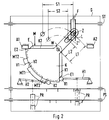
- Fig. 2 the principle of the device according to the invention is shown.
- a housing G an adjusting slide ST and two test slides PS are mounted as elements connected to a switch to be actuated. While the setting slide exerts the required force to change the switch on the switch tongues, the tester slide the positions of the switch tongues into the interior of the housing G.
- tester bar PR is provided, which fall into the recesses present in the tester slides and thereby actuate an electrical contact (not shown) as soon as the tester slides have reached a position which corresponds to an end position of the switch tongue connected to them.
- the control slide ST is driven by a control crank K which is rotatable about a shaft W mounted in the housing base.
- This control crank is designed as a double lever.
- a first lever arm, which drives the adjusting slide ST, has an elongated hole L, in which a pin Z is adjustably arranged and engages in a parallel guide F arranged on the adjusting slide, perpendicular to its direction of movement.
- the second lever arm of the control crank K is a circular sector with almost radially aligned edges K1, K2 widened, which carries a driver MT1 bent down here approximately in the middle of its arcuate boundary.
- This driver comes into engagement with drivers MT2, MT3 of an unlocking disk E, which is guided parallel to the adjusting crank and is also rotatable about shaft D, as soon as the unlocking disk is rotated relative to the adjusting crank under the effect of a torque M by a small lead angle.
- the adjusting crank In the end positions of the switch, the adjusting crank is locked in position on the one hand by a roller R1 or R2, which is fastened to a spring-loaded lever H1 or H2, and on the other hand, a stop A1 or A2. Only the unlocking disc E is able, when it is acted upon by a motor or a hydraulic working cylinder with the torque M, with a slope E1, the roller R1 against the spring force of the lever H1 from the movement shown in FIG.
- the adjusting slide ST was moved to the left by an adjusting stroke S1.
- this stroke be smaller, e.g. B. because the slide is not near the tip of the switch tongues, but z. B., arranged in one of several drives of a crossover, engages in the middle of the switch tongues
- the actuating stroke can be adjusted here in a simple manner by moving the pin Z in the slot L into another position Z 'in which it is the center axis of the shaft W is not a distance L1 but a smaller distance L2 has.
- the positioning time remains unchanged and the settings of levers H1, H2 do not need to be changed.
- the device When the switch returns, the device returns from the last assumed end position to the starting position shown in FIG. 2.
- the individual movement processes lifting the roller R2 through the corresponding slope of the unlocking disc E during the advance, frictional connection between the driver MT3 and driver MT1 and turning of the crank handle to the end position shown completely analogous to the above-described adjusting movement.
- an articulated lever is used instead of the pin Z as a coupling element, this can be designed as a rigid rod, which is articulated at one end to the position at the position otherwise occupied by the pin Z on the control crank, with its other end at the slide valve and one with its longitudinal axis forms as acute an angle as possible. A guide on the slide valve can then be omitted.
- control slide ST is assigned a clutch which then separates the control slide ST from the locking elements determining the end positions.
Landscapes
- Engineering & Computer Science (AREA)
- Mechanical Engineering (AREA)
- Railway Tracks (AREA)
- Vehicle Body Suspensions (AREA)
- Bending Of Plates, Rods, And Pipes (AREA)
- Forklifts And Lifting Vehicles (AREA)
- Transmission Devices (AREA)
- Braking Arrangements (AREA)
Abstract
Description
Die Erfindung betrifft eine Vorrichtung zur Betätigung einer Eisenbahnweiche gemäß dem Oberbegriff des Patentanspruchs 1.The invention relates to a device for actuating a railway switch according to the preamble of
Eine derartige Vorrichtung ist z. B. aus einer Firmendruckschrift der Standard Elektrik Lorenz AG mit dem Titel "Weichenantrieb L700M" bekannt, die 1972 erschienen ist und den genannten Weichenantrieb in Aufbau und Wirkungsweise beschreibt.Such a device is e.g. B. known from a company publication of Standard Elektrik Lorenz AG with the title "Point machine L700M", which appeared in 1972 and describes the mentioned point machine in structure and mode of operation.
Eine elektrohydraulisch angetriebene Heichenstellvorrichtung ist aus der DE-OS 1952 824 bekannt. Die Stellkurbel ist hier als Winkelhebel ausgebildet, auf den das zum Umstellen der Weiche erforderliche Drehmoment durch zwei hydraulische Arbeitszylinder ausgeübt wird. Anders als bei der in der zuerst genannten Schrift beschriebenen Vorrichtung wirken die Verriegelungsmittel hier jedoch nicht unmittelbar auf die Stellkurbel ein.An electro-hydraulically driven hook setting device is known from DE-OS 1952 824. The control crank is designed here as an angle lever, on which the torque required to change the switch is exerted by two hydraulic working cylinders. In contrast to the device described in the first-mentioned document, the locking means do not act directly on the control crank.
Die bekannten Vorrichtungen sind für einen vorgegebenen Stellhub ausgelegt, der jeweils auf einen bestimmten Typ einer Weiche oder eines anderen verstellbaren Gleiselementes, mit dem die jeweilige Vorrichtung zusammenwirkt, abgestimmt ist und nicht verändert werden kann, ohne wichtige Teile auszuwechseln oder entsprechend aufwendige und teure Verstell- und Verschlußmechanismen vorzusehen. Sollen z. B. bei Weichen mit großen Radien mehrere Antriebe mit unterschiedlichen Stellhüben auf eine Weiche einwirken, wie dies z. B. in der DE-PS 19 52 823 vorgesehen ist, so müssen die einzelnen Antriebsvorrichtungen in ihren Stellhüben unterschiedlich eingestellt sein, dürfen sich aber in ihren Stellzeiten nicht voneinander unterscheiden. Dazu müssen bei mechanischen Antrieben die Getriebeübersetzungen, bei hydraulischen Antrieben die Fördervolumina der Pumpen verändert werden oder es müssen in den elektrischen Zuleitungen der Antriebe teure Frequenzumrichter vorgesehen werden.The known devices are designed for a predetermined actuating stroke, each of which is matched to a specific type of switch or other adjustable track element with which the respective device interacts, and cannot be changed without changing important parts or accordingly to provide complex and expensive adjustment and locking mechanisms. Should z. B. act on switches with large radii several drives with different strokes on a switch, as z. B. is provided in DE-PS 19 52 823, the individual drive devices must be set differently in their actuating strokes, but must not differ from one another in their actuating times. For this purpose, the gear ratios have to be changed in the case of mechanical drives, the delivery volumes of the pumps in the case of hydraulic drives or expensive frequency converters have to be provided in the electrical supply lines of the drives.
Der Erfindung liegt deshalb die Aufgabe zugrunde, eine Vorrichtung der o. g. Art anzugeben, deren Stellhub einfach verändert werden kann, ohne daß sich die Stellzeit der betätigten Weiche verändert und ohne daß Einstellungen zum Verschluß dieser Weiche geändert werden müssen.The invention is therefore based on the object of a device of the above. Specify type, the stroke can be easily changed without changing the operating time of the operated switch and without having to change settings to lock this switch.
Diese Aufgabe wird durch die im Patentanspruch 1 angegebenen Merkmale gelöst.This object is achieved by the features specified in
Die Stellkurbel verbindet hier in idealer Weise die Forderung nach einem variablen Stellweg bei unveränderter Stellzeit mit dem Vorteil, den Weichenverschluß für alle Stellwegvarianten an derselben Stelle belassen zu können. Da die Verriegelung unmittelbar an der Stellkurbel erfolgt, läßt sich der gesamte Antrieb dazuhin so kompakt aufbauen, daß er in einer Kastenschwelle Platz findet.The control crank ideally combines the demand for a variable travel with unchanged travel time with the advantage of being able to leave the switch lock in the same place for all travel variants. Since the locking takes place directly on the control crank, the entire drive can be built so compact that it can be accommodated in a box sleeper.
Ausgestaltungen der Vorrichtung nach der Erfindung sind in den Unteransprüchen angegeben. So betrifft Anspruch 2 eine besonders platzsparende Ausführung der Stellkurbel als zweiarmiger Hebel, dessen das Antriebsdrehmoment aufnehmender Arm scheibenartig verbreitert ist und sowohl Mitnehmerflächen zur Aufnahme des Antriebsdrehmoments von einer parallel geführten Entsperrscheibe wie auch Anschlagflächen zur Begrenzung des Drehwinkels und für den Eingriff von Verriegelungselementen aufweist.Embodiments of the device according to the invention are specified in the subclaims. Thus,
Die Ansprüche 3 und 4 betreffen Ausgestaltungen eines zur Kraftübertragung zwischen Stellkurbel und Stellschieber angeordneten Koppelgliedes, das ein einfacher, in einer am Stellschieber angeordneten Parallelführung gleitender Zapfen oder aber eine anstelle des Zapfens angeordnete Rolle sein kann, die eine Rollbewegung in der geringfügig weiter als der Rollendurchmesser bemessenen Führung ausführt.
Anspruch 5 betrifft eine Weiterbildung, bei der anstelle eines in eine Führung eingreifenden Zapfens ein Gelenkhebel die Kraftübertragung von der Stellkurbel auf den Stellschieber übernimmt.
Die Ansprüche 6 und 7 betreffen Möglichkeiten zur Veränderung des Abstandes zwischen Koppelglied und Drehachse der Stellkurbel. Dieser Abstand, der die Länge des Stellhubes bestimmt, kann entweder, gemäß Anspruch 6, durch Verändern der Länge des den Stellschieber antreibenden Hebelarmes der Stellkurbel oder, gemäß Anspruch 7, durch Verändern der Position des Koppelgliedes auf diesem Hebelarm verändert werden.
Anspruch 8 betrifft die Möglichkeit, die Weichenverstellvorrichtung auffahrbar zu gestalten.
Anspruch 9 betrifft ein Ausführungsbeispiel für eine platzsparende Stellkurbelverriegelung.Claim 9 relates to an embodiment for a space-saving crank lock.
Anhand von 2 Figuren soll nun ein Ausführungsbeispiel der Vorrichtung nach der Erfindung eingehend beschrieben und seine Funktion erklärt werden.
- Fig. 1
- zeigt schematisch das Prinzip eines Stellkurbel-Weichenantriebs nach dem Stand der Technik.
- Fig. 2
- zeigt das Prinzip der Vorrichtung nach der Erfindung.
- Fig. 1
- shows schematically the principle of a control switch machine according to the prior art.
- Fig. 2
- shows the principle of the device according to the invention.
In Fig. 1 ist schematisch ein Stellkurbelantrieb für eine Weiche WE wiedergegeben. Ein Motor MO treibt über eine Rutschkupplung RK, ein Ritzel R und ein Zahnrad 1 eine Schnecke 2 an.In Fig. 1, a control crank drive for a switch WE is shown schematically. A motor MO drives a
Die Schnecke ist mit einem Schrägstirnradsektor 3 im Eingriff, der um eine Welle 6 drehbar ist. Die eigentliche Stellkurbel bildet ein ebenfalls um die Welle 6 drehbarer Doppelhebel, an dessen einem Arm 5 der Stellschieber der Weiche angelenkt ist und dessen anderer Arm 4 sektorförmig verbreitert, parallel zum Schrägstirnradsektor verläuft und mit diesem über einen Mitnehmer 7 und eine z. B. als Langloch in azimutaler Richtung ausgebildete Ausnehmung, in die der Mitnehmer hineinragt, verbunden ist.The worm is in engagement with a helical gear sector 3, which is rotatable about a
Beim Stellvorgang wird, ausgehend von einer Endlage der Weiche, in der Schrägstirnradsektor 3 und Stellkurbel 4 an einem Anschlag anliegen und in der die Stellkurbel gegen eine vom Anschlag weg gerichtete Bewegung durch einen Sperrhebel 8 verriegelt ist, der Schrägstirnradsektor über die Schnecke 2 angetrieben. Noch bevor der Mitnehmer 7 Kraft auf die Stellkurbel ausübt, hebt der Schrägstirnradsektor über eine Schräge 12 den Sperrhebel 8, 8a gegen eine ihn in einer die Drehbewegung der Stellkurbel blockierenden Ruhelage haltende Federkraft aus und gibt damit die Stellkurbel frei. Mit dem Ausheben des Sperrhebels 8 wird außerdem ein Kontakt 10 geschlossen, der den beginnenden Weichenumlauf z. B. an ein Stellwerk meldet.During the actuating process, starting from an end position of the switch, the helical gear sector 3 and
Der ausgehobene Stellhebel, der an seinem Ende eine Rolle tragen kann, gleitet oder rollt nun auf der kreisbogenförmigen Randfläche des sektorförmigen Teils der Stellkurbel bis nach Erreichen der anderen Endlage der Weiche der für die Verriegelung der Stellkurbel in dieser Endlage vorgesehene Sperrhebel 9 hinter die Begrenzung des sektorförmigen Teils 4 der Stellkurbel einfällt. Über einen mit dem Sperrhebel 9 verbundenen Kontakt 11 wird die neue Weichen lage an das Stellwerk gemeldet. Die Rückstellung der Weiche erfolgt in analoger Weise.The lifted control lever, which can carry a roller at its end, now slides or rolls on the arcuate edge surface of the sector-shaped part of the control crank until after reaching other end position of the switch, the locking lever 9 provided for locking the control crank in this end position falls behind the boundary of the sector-
Anstelle eines über ein Getriebe an die Stellkurbel angekoppelten Motors, können selbstverständlich auch hydraulische Arbeitszylinder zur Ausübung eines Drehmomentes auf die Stellkurbel zum Einsatz kommen, wie dies bei elektrohydraulischen Weichenantrieben der Fall ist.Instead of a motor coupled to the control crank via a gear, hydraulic working cylinders can of course also be used to exert a torque on the control crank, as is the case with electrohydraulic point machines.
In Fig. 2 ist das Prinzip der Vorrichtung nach der Erfindung wiedergegeben. In einem Gehäuse G sind als mit einer zu betätigenden Weiche verbundene Elemente ein Stellschieber ST und zwei Prüferschieber PS gelagert. Während der Stellschieber die zum Umstellen der Weiche erforderliche Stellkraft auf die Weichenzungen ausübt, übertragen die Prüferschieber die Positionen der Weichenzungen ins Innere des Gehäuses G. Dort sind dann z. B. Prüferriegel PR vorgesehen, die in in den Prüferschiebern vorhandene Ausnehmungen einfallen und dabei einen nicht dargestellten elektrischen Kontakt betätigen, sobald die Prüferschieber eine Position erreicht haben, die einer Endposition der jeweils mit ihnen verbundenen Weichenzunge entspricht.In Fig. 2 the principle of the device according to the invention is shown. In a housing G, an adjusting slide ST and two test slides PS are mounted as elements connected to a switch to be actuated. While the setting slide exerts the required force to change the switch on the switch tongues, the tester slide the positions of the switch tongues into the interior of the housing G. There are z. B. tester bar PR is provided, which fall into the recesses present in the tester slides and thereby actuate an electrical contact (not shown) as soon as the tester slides have reached a position which corresponds to an end position of the switch tongue connected to them.
Der Antrieb des Stellschiebers ST erfolgt über eine Stellkurbel K, die um eine im Gehäuseboden gelagerte Welle W drehbar ist. Diese Stellkurbel ist als Doppelhebel ausgebildet. Ein erster Hebelarm, der den Stellschieber ST antreibt, besitzt ein Langloch L, in dem ein Zapfen Z verstellbar angeordnet ist und in eine am Stellschieber, senkrecht zu dessen Bewegungsrichtung angeordnete Parallelführung F eingreift. Der zweite Hebelarm der Stellkurbel K ist zu einem Kreissektor mit nahezu radial ausgerichteten Kanten K1, K2 verbreitert, der etwa in der Mitte seiner kreisbogenförmigen Begrenzung einen hier nach unten abgekröpften Mitnehmer MT1 trägt. Dieser Mitnehmer kommt mit Mitnehmern MT2, MT3 einer parallel zur Stellkurbel geführten, ebenfalls um die Welle D drehbaren Entsperrscheibe E in Eingriff, sobald die Entsperrscheibe gegenüber der Stellkurbel unter der Wirkung eines Drehmomentes M um einen kleinen Vorlaufwinkel gedreht wird.The control slide ST is driven by a control crank K which is rotatable about a shaft W mounted in the housing base. This control crank is designed as a double lever. A first lever arm, which drives the adjusting slide ST, has an elongated hole L, in which a pin Z is adjustably arranged and engages in a parallel guide F arranged on the adjusting slide, perpendicular to its direction of movement. The second lever arm of the control crank K is a circular sector with almost radially aligned edges K1, K2 widened, which carries a driver MT1 bent down here approximately in the middle of its arcuate boundary. This driver comes into engagement with drivers MT2, MT3 of an unlocking disk E, which is guided parallel to the adjusting crank and is also rotatable about shaft D, as soon as the unlocking disk is rotated relative to the adjusting crank under the effect of a torque M by a small lead angle.
In den Endlagen der Weiche ist die Stellkurbel jeweils einerseits durch eine Rolle R1 oder R2, die an einem federkraftbeaufschlagten Hebel H1 bzw. H2 befestigt ist, und andererseits einen Anschlag A1 bzw. A2 in ihrer Lage verriegelt. Allein die Entsperrscheibe E ist in der Lage, wenn sie von einem nicht dargestellten Motor oder einem hydraulischen Arbeitszylinder mit dem Drehmoment M beaufschlagt wird, mit einer Schräge E1 die Rolle R1 gegen die Federkraft des Hebels H1 aus der in Fig. 2 dargestellten, die Bewegung der Stellkurbel sperrenden Lage zu drücken und mit der Vorderfläche V1 ihres Mitnehmers MT2, die nach Drehung um den Vorlaufwinkel gegen die zum Mitnehmer MT2 hin gerichtete Seitenfläche V2 des Mitnehmers MT1 der Stellkurbel läuft, die Stellkurbel mitzuführen, bis die Stellkurbelkante K1 den Anschlag A2 erreicht hat und die am Hebel H2 befestigte Rolle R2 hinter der anderen Kante K2 der Stellkurbel, die ausgangs der Bewegung am Anschlag Al angelegen hat, eingefallen ist.In the end positions of the switch, the adjusting crank is locked in position on the one hand by a roller R1 or R2, which is fastened to a spring-loaded lever H1 or H2, and on the other hand, a stop A1 or A2. Only the unlocking disc E is able, when it is acted upon by a motor or a hydraulic working cylinder with the torque M, with a slope E1, the roller R1 against the spring force of the lever H1 from the movement shown in FIG. 2 the position of the crank locking position and with the front surface V1 of its driver MT2, which after rotation by the lead angle against the side surface V2 of the driver MT1 facing the driver MT2 runs the actuator crank until the actuator crank edge K1 has reached the stop A2 and the roller R2 fastened to the lever H2 has fallen behind the other edge K2 of the control crank, which has placed against the stop Al as a result of the movement.
Während des Drehvorgangs der Stellkurbel wurde der Stellschieber ST um einen Stellhub S1 nach links bewegt. Soll dieser Stellhub kleiner sein, z. B. weil der Stellschieber nicht in der Nähe der Spitze der Weichenzungen, sondern z. B., in einem von mehreren Antrieben einer Langweiche angeordnet, in der Mitte der Weichenzungen angreift, so kann der Stellhub hier auf einfache Weise verstellt werden, indem der Zapfen Z im Langloch L in eine andere Position Z' verschoben wird, in der er von der Mittelachse der Welle W nicht einen Abstand L1 sondern einen kleineren Abstand L2 hat. Wie aus der Figur ersichtlich, verkürzt sich dadurch der Stellhub auf einen Weg S2. Die Stellzeit bleibt dabei unverändert und auch die Einstellungen der Hebel H1, H2 brauchen nicht verändert zu werden. Beim Weichenrücklauf kehrt die Vorrichtung aus der zuletzt eingenommenen Endlage in die in Fig. 2 dargestellte Ausgangslage zurück. Dabei laufen die einzelnen Bewegungsvorgänge, Ausheben der Rolle R2 durch die entsprechende Schräge der Entsperrscheibe E während des Vorlaufes, Kraftschluß zwischen Mitnehmer MT3 und Mitnehmer MT1 und Mitdrehen der Stellkurbel bis in die dargestellte Endlage völlig analog zur vorstehend beschriebenen Stellbewegung ab.During the turning process of the adjusting crank, the adjusting slide ST was moved to the left by an adjusting stroke S1. Should this stroke be smaller, e.g. B. because the slide is not near the tip of the switch tongues, but z. B., arranged in one of several drives of a crossover, engages in the middle of the switch tongues, the actuating stroke can be adjusted here in a simple manner by moving the pin Z in the slot L into another position Z 'in which it is the center axis of the shaft W is not a distance L1 but a smaller distance L2 has. As can be seen from the figure, this shortens the actuating stroke to a path S2. The positioning time remains unchanged and the settings of levers H1, H2 do not need to be changed. When the switch returns, the device returns from the last assumed end position to the starting position shown in FIG. 2. The individual movement processes, lifting the roller R2 through the corresponding slope of the unlocking disc E during the advance, frictional connection between the driver MT3 and driver MT1 and turning of the crank handle to the end position shown completely analogous to the above-described adjusting movement.
Wird anstelle des Zapfens Z als Koppelelement ein Gelenkhebel verwendet, so kann dieser als starre Stange ausgebildet sein, die mit ihrem einen Ende an der sonst vom Zapfen Z eingenommenen Stelle an der Stellkurbel, mit ihrem anderen Ende am Stellschieber angelenkt ist und mit dessen Längsachse einen möglichst spitzen Winkel bildet. Eine Führung am Stellschieber kann dann entfallen.If an articulated lever is used instead of the pin Z as a coupling element, this can be designed as a rigid rod, which is articulated at one end to the position at the position otherwise occupied by the pin Z on the control crank, with its other end at the slide valve and one with its longitudinal axis forms as acute an angle as possible. A guide on the slide valve can then be omitted.
Für den Fall, daß die Eisenbahnweiche aus der falschen Richtung befahren wird (Auffahren der Weiche) wird dem Stellschieber ST eine Kupplung zugeordnet, die dann den Stellschieber ST von den die Endlagen bestimmenden Verriegelungselementen trennt.In the event that the railroad switch is driven from the wrong direction (opening of the switch), the control slide ST is assigned a clutch which then separates the control slide ST from the locking elements determining the end positions.
Claims (9)
dadurch gekennzeichnet, daß die Stellkurbel (K) über ein in seinem Abstand von der Drehachse verstellbares Koppelglied (Z) mit dem Stellschieber (ST) kraftschlüssig verbunden ist.Device for actuating a railway switch (WE) with a drive element (MO), an actuating slide (ST) actuated by the latter via a control crank (K) designed as a lever rotatable about an axis and acting on the switch tongues and with locking means (R1, R2, H1 , H2), which hold the control crank in its respective end position after completion of an adjustment movement,
characterized in that the control crank (K) is non-positively connected to the control slide (ST) via a coupling member (Z) whose distance from the axis of rotation is adjustable.
dadurch gekennzeichnet, daß die Stellkurbel als mindestens zweiarmiger Hebel ausgebildet ist, von dem ein nicht mit dem Stellschieber verbundener Hebelarm als Sektor eines Kreises ausgebildet ist, durch dessen Mittelpunkt die Drehachse verläuft, daß eine im wesentlichen parallel zu dem Kreissektor angeordnete, vorzugsweise in der Größe des Kreissektors ausgebildete Entsperrscheibe (E) um die Drehachse drehbar angeordnet ist, welche ein vom Antriebselement auf die Stellkurbel zu übertragendes Drehmoment (M) aufnimmt und die Stellkurbel über an Stellkurbel und Entsperrscheibe angebrachte, aus einer einer Endlage des Stellschiebers entsprechenden Lage heraus nach kurzem Vorlauf miteinander in Eingriff kommende Mitnehmer (MT1, MT2, MT3) bis in eine der anderen Endlage des Stellschiebers entsprechende Endposition mitdreht und welche beiderseits Schrägflächen (El, E2) aufweist, die während des Vorlaufs ein die Drehung der Stellkurbel zuvor verhinderndes, mit einer Anschlagsfläche (K1, K2) der Stellkurbel in Eingriff stehendes Verriegelungselement (R1, R2) gegen eine Rückstellkraft aus der Verriegelungsstellung drücken.Device according to claim 1,
characterized in that the control crank is designed as an at least two-armed lever, of which a lever arm which is not connected to the adjusting slide is designed as a sector of a circle, through the center of which the axis of rotation runs, that an essentially parallel to the circular sector, preferably in size of the circular sector designed unlocking disc (E) is arranged rotatable about the axis of rotation, which receives a torque (M) to be transmitted from the drive element to the actuating crank and the actuating crank via to the actuating crank and Unlocking disc attached, from a position corresponding to an end position of the slide valve, after a short advance, engaging drivers (MT1, MT2, MT3) turn to an end position corresponding to the other end position of the slide valve and which has inclined surfaces (El, E2) on both sides, which during the advance, press a locking element (R1, R2) which previously prevents rotation of the control crank and engages with a stop surface (K1, K2) of the control crank against a restoring force from the locking position.
dadurch gekennzeichnet, daß das in seinem Abstand von der Drehachse verstellbare Koppelglied (Z) ein zur Längsausdehnung des Hebelarmes senkrechter Zapfen ist, der in eine am Stellschieber, vorzugsweise senkrecht zu dessen Bewegungsrichtung angeordnete Führung (F) eingreift und in dieser beweglich ist.Device according to claim 1 or 2,
characterized in that the coupling member (Z), which is adjustable in its distance from the axis of rotation, is a pin perpendicular to the longitudinal extension of the lever arm, which engages in a guide (F) arranged on the adjusting slide, preferably perpendicular to its direction of movement, and is movable therein.
dadurch gekennzeichnet, daß der Zapfen Lager für eine Rolle ist.Device according to claim 3,
characterized in that the pin is a roller bearing.
dadurch gekennzeichnet, daß das in seinem Abstand von der Drehachse verstellbare Koppelglied von einem ersten Gelenk eines Gelenkhebels gebildet wird, der in spitzem Winkel zum Stellschieber angeordnet und mit diesem über ein weiteres Gelenk verbunden ist.Device according to claim 1 or 2,
characterized in that the coupling member, which is adjustable in its distance from the axis of rotation, is formed by a first joint of an articulated lever which is arranged at an acute angle to the adjusting slide and is connected to the latter via a further joint.
dadurch gekennzeichnet, daß der das Koppelglied tragende Hebelarm der Stellkurbel in seiner Länge verstellbar ist.Device according to one of claims 1 to 5,
characterized in that the lever arm of the control crank carrying the coupling member is adjustable in length.
dadurch gekennzeichnet, daß das Koppelglied auf dem es tragenden Hebelarm in Längsrichtung verschiebbar angeordnet, oder in vorbereitete, in unterschiedlichen Entfernungen zur Drehachse angeordnete Aufnahmen einsetzbar ist.Device according to one of claims 1 to 5,
characterized in that the coupling member is arranged on the lever arm carrying it so as to be displaceable in the longitudinal direction, or can be used in prepared receptacles arranged at different distances from the axis of rotation.
dadurch gekennzeichnet, daß der Stellschieber (ST) mit einer Kupplung derart verbunden ist, daß beim stumpf Befahren der Eisenbahnweiche (WE) aus der falschen Richtung (Auffahren der Weiche) der Stellschieber von den Verriegelungselementen getrennt wird.Device according to one of claims 1 to 4,
characterized in that the adjusting slide (ST) is connected to a coupling in such a way that when the railway switch (WE) is bluntly driven from the wrong direction (moving the switch), the adjusting slide is separated from the locking elements.
dadurch gekennzeichnet, daß als Verriegelungselemente Rollen (R1, R2) vorgesehen sind, die an in den Endlagen des Stellschiebers durch vorgespannte Federn in einer Ruhelage gehaltenen Hebeln (H1, H2) befestigt sind und im Zusammenwirken mit je einer Anschlagsfläche (K1, K2) des das Antriebsdrehmoment aufnehmenden Hebelarms der Stellkurbel deren Bewegung verhindern, daß die Rollen so breit sind, daß sie in die Bahn der Entsperrscheibe (E) ragen und daß die Schrägflächen (E1, E2) in den Bereichen des Randes der Entsperrscheibe vorgesehen sind, die während der Drehbewegung der Entsperrscheibe zuerst mit einer Rolle in Kontakt kommen.Device according to one of claims 2 to 8,
characterized in that rollers (R1, R2) are provided as locking elements, which are fastened to levers (H1, H2) held in a rest position by prestressed springs in the end positions of the adjusting slide and in cooperation with a stop surface (K1, K2) each the drive torque absorbing lever arm of the crank whose movement prevent the rollers from being so wide that they protrude into the path of the unlocking disc (E) and that the inclined surfaces (E1, E2) are provided in the regions of the edge of the unlocking disc which are used during the Rotation of the unlocking disc first comes into contact with a roller.
Applications Claiming Priority (2)
| Application Number | Priority Date | Filing Date | Title |
|---|---|---|---|
| DE19538966 | 1995-10-19 | ||
| DE19538966A DE19538966A1 (en) | 1995-10-19 | 1995-10-19 | Point machine with adjustable stroke |
Publications (3)
| Publication Number | Publication Date |
|---|---|
| EP0769439A1 true EP0769439A1 (en) | 1997-04-23 |
| EP0769439B1 EP0769439B1 (en) | 2002-07-03 |
| EP0769439B2 EP0769439B2 (en) | 2005-08-10 |
Family
ID=7775280
Family Applications (1)
| Application Number | Title | Priority Date | Filing Date |
|---|---|---|---|
| EP96440086A Expired - Lifetime EP0769439B2 (en) | 1995-10-19 | 1996-10-14 | Switch drive with adjustable stroke |
Country Status (4)
| Country | Link |
|---|---|
| EP (1) | EP0769439B2 (en) |
| AT (1) | ATE220020T1 (en) |
| DE (2) | DE19538966A1 (en) |
| HU (1) | HUP9602869A3 (en) |
Cited By (2)
| Publication number | Priority date | Publication date | Assignee | Title |
|---|---|---|---|---|
| EP1459954A1 (en) * | 2003-03-21 | 2004-09-22 | Alcatel | Railway points actuating system |
| FR2905922A1 (en) * | 2006-09-14 | 2008-03-21 | Vossloh Cogifer Sa | MECHANISM FOR MANEUVERING NEEDLES |
Citations (2)
| Publication number | Priority date | Publication date | Assignee | Title |
|---|---|---|---|---|
| DE1530403A1 (en) * | 1965-05-18 | 1969-10-02 | Standard Elek K Lorenz Ag | Coupling device on electrical point machines for railway safety systems |
| DE1530404A1 (en) * | 1965-06-14 | 1969-10-02 | Standard Elek K Lorenz Ag | Coupling device on electrical point machines for railway safety systems |
Family Cites Families (8)
| Publication number | Priority date | Publication date | Assignee | Title |
|---|---|---|---|---|
| DE948164C (en) * | 1953-07-03 | 1956-08-30 | Lorenz C Ag | Tongue checking device for electrical point machines |
| DE1055578B (en) * | 1956-08-08 | 1959-04-23 | Standard Elektrik Lorenz Ag | Coupling device on electrical point machines in railway safety systems |
| DE1116713B (en) * | 1957-03-06 | 1961-11-09 | Standard Elektrik Lorenz Ag | Coupling device on electrical point machines in railway safety systems |
| DE1124538B (en) * | 1958-01-27 | 1962-03-01 | Licentia Gmbh | Electromotive point actuator |
| FR1382106A (en) * | 1963-06-27 | 1964-12-18 | Westinghouse Freins & Signaux | Method for controlling heel-capable needles and a motor for implementing said method |
| NL6901277A (en) * | 1969-01-24 | 1970-07-28 | ||
| FR2510059B1 (en) * | 1981-07-23 | 1987-12-04 | Dietrich & Cie De | MECHANISM FOR HANDLING DRAWINGS OF RAILWAYS OF THE "HOLD TYPE" |
| SE506183C2 (en) * | 1993-05-27 | 1997-11-17 | Abb Daimler Benz Transp | Device at railroad tracks for the change of track gear |
-
1995
- 1995-10-19 DE DE19538966A patent/DE19538966A1/en active Pending
-
1996
- 1996-10-14 DE DE59609398T patent/DE59609398D1/en not_active Expired - Lifetime
- 1996-10-14 EP EP96440086A patent/EP0769439B2/en not_active Expired - Lifetime
- 1996-10-14 AT AT96440086T patent/ATE220020T1/en active
- 1996-10-17 HU HU9602869A patent/HUP9602869A3/en unknown
Patent Citations (2)
| Publication number | Priority date | Publication date | Assignee | Title |
|---|---|---|---|---|
| DE1530403A1 (en) * | 1965-05-18 | 1969-10-02 | Standard Elek K Lorenz Ag | Coupling device on electrical point machines for railway safety systems |
| DE1530404A1 (en) * | 1965-06-14 | 1969-10-02 | Standard Elek K Lorenz Ag | Coupling device on electrical point machines for railway safety systems |
Cited By (5)
| Publication number | Priority date | Publication date | Assignee | Title |
|---|---|---|---|---|
| EP1459954A1 (en) * | 2003-03-21 | 2004-09-22 | Alcatel | Railway points actuating system |
| FR2905922A1 (en) * | 2006-09-14 | 2008-03-21 | Vossloh Cogifer Sa | MECHANISM FOR MANEUVERING NEEDLES |
| WO2008031956A3 (en) * | 2006-09-14 | 2008-05-15 | Vossloh Cogifer Sa | Mechanism for operating switch points |
| US7913956B2 (en) | 2006-09-14 | 2011-03-29 | Vossloh Cogifer | Mechanism for operating switch points |
| CN101528527B (en) * | 2006-09-14 | 2014-04-23 | 福斯洛-科吉费尔公司 | Mechanism for operating switch points |
Also Published As
| Publication number | Publication date |
|---|---|
| DE59609398D1 (en) | 2002-08-08 |
| HU9602869D0 (en) | 1996-12-30 |
| HUP9602869A3 (en) | 2001-04-28 |
| DE19538966A1 (en) | 1997-04-24 |
| HUP9602869A2 (en) | 1998-05-28 |
| EP0769439B1 (en) | 2002-07-03 |
| ATE220020T1 (en) | 2002-07-15 |
| EP0769439B2 (en) | 2005-08-10 |
Similar Documents
| Publication | Publication Date | Title |
|---|---|---|
| DE3912871C2 (en) | Tool holder for a punching tool with selectable activatable punches for a punching machine | |
| EP0160719A1 (en) | Single lever setting device | |
| DE19535578B4 (en) | Point machine with inner lock | |
| EP0769439B1 (en) | Switch drive with adjustable stroke | |
| DE3018633C2 (en) | Electric hammer drill with switchable drill drive | |
| EP0814996B1 (en) | Point switch mechanism | |
| EP2017798B1 (en) | Device for counting out coins from a pair of adjacent coin tubes | |
| EP0037428B1 (en) | Unbalanced-mass vibrator with switching clutch | |
| EP4204276A1 (en) | Locking device and locking method for a switch point drive and switch point drive | |
| DE19525012A1 (en) | Point machine | |
| DE4333726A1 (en) | Multiple adjustment devices drive unit - has electromotor for operating several adjustment devices via different selectable coupling elements | |
| DE3714705A1 (en) | SWITCHING DEVICE ON A MAGNETIC TAPE DEVICE FOR AUTOREVERSE OPERATION | |
| EP2297015B1 (en) | Driving device for switching mechanical elements | |
| DE2754542A1 (en) | Document printer pressure unit - has catches rotatably attached to two spindles and is attached on parts extending from two stops | |
| CH664233A5 (en) | DRIVING DEVICE FOR AN ELECTRICAL SWITCHGEAR, ESPECIALLY FOR A DISCONNECTOR. | |
| DE19959458A1 (en) | Setting machine | |
| DE2314585C3 (en) | Wiper drive | |
| DE530769C (en) | Connection of a calculating machine with a card punching machine | |
| DE2922319A1 (en) | Shedding mechanism operated by axially-sliding clutch - connecting drive wheel with coaxial eccentric operating lift levers | |
| EP4299408A1 (en) | Switch adjusting device | |
| DE2521970A1 (en) | Points switching unit for railways - has multiple actuators connected via mechanical linkage to keep tracks spaced correctly | |
| EP0157011B1 (en) | Lamellar blind closure | |
| EP0394863B1 (en) | Device for positioning movable carriages e.g. on machines tools | |
| DE750335C (en) | Identifier with changeable identifier | |
| DE677686C (en) | Switching device for gear change transmissions, especially of motor vehicles |
Legal Events
| Date | Code | Title | Description |
|---|---|---|---|
| PUAI | Public reference made under article 153(3) epc to a published international application that has entered the european phase |
Free format text: ORIGINAL CODE: 0009012 |
|
| AK | Designated contracting states |
Kind code of ref document: A1 Designated state(s): AT CH DE ES FR GB IT LI SE |
|
| 17P | Request for examination filed |
Effective date: 19970823 |
|
| RAP3 | Party data changed (applicant data changed or rights of an application transferred) |
Owner name: ALCATEL |
|
| RAP3 | Party data changed (applicant data changed or rights of an application transferred) |
Owner name: ALCATEL |
|
| GRAG | Despatch of communication of intention to grant |
Free format text: ORIGINAL CODE: EPIDOS AGRA |
|
| 17Q | First examination report despatched |
Effective date: 20010903 |
|
| GRAG | Despatch of communication of intention to grant |
Free format text: ORIGINAL CODE: EPIDOS AGRA |
|
| GRAH | Despatch of communication of intention to grant a patent |
Free format text: ORIGINAL CODE: EPIDOS IGRA |
|
| GRAH | Despatch of communication of intention to grant a patent |
Free format text: ORIGINAL CODE: EPIDOS IGRA |
|
| GRAA | (expected) grant |
Free format text: ORIGINAL CODE: 0009210 |
|
| AK | Designated contracting states |
Kind code of ref document: B1 Designated state(s): AT CH DE ES FR GB IT LI SE |
|
| REF | Corresponds to: |
Ref document number: 220020 Country of ref document: AT Date of ref document: 20020715 Kind code of ref document: T |
|
| REG | Reference to a national code |
Ref country code: CH Ref legal event code: EP |
|
| GBT | Gb: translation of ep patent filed (gb section 77(6)(a)/1977) |
Effective date: 20020703 |
|
| REG | Reference to a national code |
Ref country code: CH Ref legal event code: NV Representative=s name: CABINET ROLAND NITHARDT CONSEILS EN PROPRIETE INDU |
|
| REF | Corresponds to: |
Ref document number: 59609398 Country of ref document: DE Date of ref document: 20020808 |
|
| ET | Fr: translation filed | ||
| PG25 | Lapsed in a contracting state [announced via postgrant information from national office to epo] |
Ref country code: ES Free format text: LAPSE BECAUSE OF FAILURE TO SUBMIT A TRANSLATION OF THE DESCRIPTION OR TO PAY THE FEE WITHIN THE PRESCRIBED TIME-LIMIT Effective date: 20030130 |
|
| PLBI | Opposition filed |
Free format text: ORIGINAL CODE: 0009260 |
|
| PLBF | Reply of patent proprietor to notice(s) of opposition |
Free format text: ORIGINAL CODE: EPIDOS OBSO |
|
| 26 | Opposition filed |
Opponent name: SIEMENS AG Effective date: 20030401 |
|
| PLBB | Reply of patent proprietor to notice(s) of opposition received |
Free format text: ORIGINAL CODE: EPIDOSNOBS3 |
|
| PUAH | Patent maintained in amended form |
Free format text: ORIGINAL CODE: 0009272 |
|
| STAA | Information on the status of an ep patent application or granted ep patent |
Free format text: STATUS: PATENT MAINTAINED AS AMENDED |
|
| 27A | Patent maintained in amended form |
Effective date: 20050810 |
|
| AK | Designated contracting states |
Kind code of ref document: B2 Designated state(s): AT CH DE ES FR GB IT LI SE |
|
| REG | Reference to a national code |
Ref country code: CH Ref legal event code: AEN Free format text: AUFRECHTERHALTUNG DES PATENTES IN GEAENDERTER FORM |
|
| REG | Reference to a national code |
Ref country code: ES Ref legal event code: FD2A Effective date: 20021015 |
|
| GBTA | Gb: translation of amended ep patent filed (gb section 77(6)(b)/1977) | ||
| REG | Reference to a national code |
Ref country code: SE Ref legal event code: RPEO |
|
| ET3 | Fr: translation filed ** decision concerning opposition | ||
| REG | Reference to a national code |
Ref country code: FR Ref legal event code: PLFP Year of fee payment: 20 |
|
| PGFP | Annual fee paid to national office [announced via postgrant information from national office to epo] |
Ref country code: DE Payment date: 20151006 Year of fee payment: 20 Ref country code: CH Payment date: 20151012 Year of fee payment: 20 Ref country code: GB Payment date: 20151014 Year of fee payment: 20 Ref country code: IT Payment date: 20151026 Year of fee payment: 20 |
|
| PGFP | Annual fee paid to national office [announced via postgrant information from national office to epo] |
Ref country code: FR Payment date: 20151008 Year of fee payment: 20 Ref country code: SE Payment date: 20151013 Year of fee payment: 20 Ref country code: AT Payment date: 20151012 Year of fee payment: 20 |
|
| REG | Reference to a national code |
Ref country code: DE Ref legal event code: R071 Ref document number: 59609398 Country of ref document: DE |
|
| REG | Reference to a national code |
Ref country code: CH Ref legal event code: PL |
|
| REG | Reference to a national code |
Ref country code: GB Ref legal event code: PE20 Expiry date: 20161013 |
|
| REG | Reference to a national code |
Ref country code: SE Ref legal event code: EUG |
|
| REG | Reference to a national code |
Ref country code: AT Ref legal event code: MK07 Ref document number: 220020 Country of ref document: AT Kind code of ref document: T Effective date: 20161014 |
|
| PG25 | Lapsed in a contracting state [announced via postgrant information from national office to epo] |
Ref country code: GB Free format text: LAPSE BECAUSE OF EXPIRATION OF PROTECTION Effective date: 20161013 |