EP0769403B1 - Hybrid vehicle drive system having two motor generator units and engine starting means - Google Patents
Hybrid vehicle drive system having two motor generator units and engine starting means Download PDFInfo
- Publication number
- EP0769403B1 EP0769403B1 EP96116592A EP96116592A EP0769403B1 EP 0769403 B1 EP0769403 B1 EP 0769403B1 EP 96116592 A EP96116592 A EP 96116592A EP 96116592 A EP96116592 A EP 96116592A EP 0769403 B1 EP0769403 B1 EP 0769403B1
- Authority
- EP
- European Patent Office
- Prior art keywords
- motor
- engine
- generator
- vehicle
- starting
- Prior art date
- Legal status (The legal status is an assumption and is not a legal conclusion. Google has not performed a legal analysis and makes no representation as to the accuracy of the status listed.)
- Expired - Lifetime
Links
Images


Classifications
-
- B—PERFORMING OPERATIONS; TRANSPORTING
- B60—VEHICLES IN GENERAL
- B60K—ARRANGEMENT OR MOUNTING OF PROPULSION UNITS OR OF TRANSMISSIONS IN VEHICLES; ARRANGEMENT OR MOUNTING OF PLURAL DIVERSE PRIME-MOVERS IN VEHICLES; AUXILIARY DRIVES FOR VEHICLES; INSTRUMENTATION OR DASHBOARDS FOR VEHICLES; ARRANGEMENTS IN CONNECTION WITH COOLING, AIR INTAKE, GAS EXHAUST OR FUEL SUPPLY OF PROPULSION UNITS IN VEHICLES
- B60K6/00—Arrangement or mounting of plural diverse prime-movers for mutual or common propulsion, e.g. hybrid propulsion systems comprising electric motors and internal combustion engines ; Control systems therefor, i.e. systems controlling two or more prime movers, or controlling one of these prime movers and any of the transmission, drive or drive units Informative references: mechanical gearings with secondary electric drive F16H3/72; arrangements for handling mechanical energy structurally associated with the dynamo-electric machine H02K7/00; machines comprising structurally interrelated motor and generator parts H02K51/00; dynamo-electric machines not otherwise provided for in H02K see H02K99/00
- B60K6/20—Arrangement or mounting of plural diverse prime-movers for mutual or common propulsion, e.g. hybrid propulsion systems comprising electric motors and internal combustion engines ; Control systems therefor, i.e. systems controlling two or more prime movers, or controlling one of these prime movers and any of the transmission, drive or drive units Informative references: mechanical gearings with secondary electric drive F16H3/72; arrangements for handling mechanical energy structurally associated with the dynamo-electric machine H02K7/00; machines comprising structurally interrelated motor and generator parts H02K51/00; dynamo-electric machines not otherwise provided for in H02K see H02K99/00 the prime-movers consisting of electric motors and internal combustion engines, e.g. HEVs
- B60K6/22—Arrangement or mounting of plural diverse prime-movers for mutual or common propulsion, e.g. hybrid propulsion systems comprising electric motors and internal combustion engines ; Control systems therefor, i.e. systems controlling two or more prime movers, or controlling one of these prime movers and any of the transmission, drive or drive units Informative references: mechanical gearings with secondary electric drive F16H3/72; arrangements for handling mechanical energy structurally associated with the dynamo-electric machine H02K7/00; machines comprising structurally interrelated motor and generator parts H02K51/00; dynamo-electric machines not otherwise provided for in H02K see H02K99/00 the prime-movers consisting of electric motors and internal combustion engines, e.g. HEVs characterised by apparatus, components or means specially adapted for HEVs
- B60K6/40—Arrangement or mounting of plural diverse prime-movers for mutual or common propulsion, e.g. hybrid propulsion systems comprising electric motors and internal combustion engines ; Control systems therefor, i.e. systems controlling two or more prime movers, or controlling one of these prime movers and any of the transmission, drive or drive units Informative references: mechanical gearings with secondary electric drive F16H3/72; arrangements for handling mechanical energy structurally associated with the dynamo-electric machine H02K7/00; machines comprising structurally interrelated motor and generator parts H02K51/00; dynamo-electric machines not otherwise provided for in H02K see H02K99/00 the prime-movers consisting of electric motors and internal combustion engines, e.g. HEVs characterised by apparatus, components or means specially adapted for HEVs characterised by the assembly or relative disposition of components
-
- B—PERFORMING OPERATIONS; TRANSPORTING
- B60—VEHICLES IN GENERAL
- B60W—CONJOINT CONTROL OF VEHICLE SUB-UNITS OF DIFFERENT TYPE OR DIFFERENT FUNCTION; CONTROL SYSTEMS SPECIALLY ADAPTED FOR HYBRID VEHICLES; ROAD VEHICLE DRIVE CONTROL SYSTEMS FOR PURPOSES NOT RELATED TO THE CONTROL OF A PARTICULAR SUB-UNIT
- B60W20/00—Control systems specially adapted for hybrid vehicles
- B60W20/10—Controlling the power contribution of each of the prime movers to meet required power demand
- B60W20/15—Control strategies specially adapted for achieving a particular effect
-
- B—PERFORMING OPERATIONS; TRANSPORTING
- B60—VEHICLES IN GENERAL
- B60K—ARRANGEMENT OR MOUNTING OF PROPULSION UNITS OR OF TRANSMISSIONS IN VEHICLES; ARRANGEMENT OR MOUNTING OF PLURAL DIVERSE PRIME-MOVERS IN VEHICLES; AUXILIARY DRIVES FOR VEHICLES; INSTRUMENTATION OR DASHBOARDS FOR VEHICLES; ARRANGEMENTS IN CONNECTION WITH COOLING, AIR INTAKE, GAS EXHAUST OR FUEL SUPPLY OF PROPULSION UNITS IN VEHICLES
- B60K6/00—Arrangement or mounting of plural diverse prime-movers for mutual or common propulsion, e.g. hybrid propulsion systems comprising electric motors and internal combustion engines ; Control systems therefor, i.e. systems controlling two or more prime movers, or controlling one of these prime movers and any of the transmission, drive or drive units Informative references: mechanical gearings with secondary electric drive F16H3/72; arrangements for handling mechanical energy structurally associated with the dynamo-electric machine H02K7/00; machines comprising structurally interrelated motor and generator parts H02K51/00; dynamo-electric machines not otherwise provided for in H02K see H02K99/00
- B60K6/20—Arrangement or mounting of plural diverse prime-movers for mutual or common propulsion, e.g. hybrid propulsion systems comprising electric motors and internal combustion engines ; Control systems therefor, i.e. systems controlling two or more prime movers, or controlling one of these prime movers and any of the transmission, drive or drive units Informative references: mechanical gearings with secondary electric drive F16H3/72; arrangements for handling mechanical energy structurally associated with the dynamo-electric machine H02K7/00; machines comprising structurally interrelated motor and generator parts H02K51/00; dynamo-electric machines not otherwise provided for in H02K see H02K99/00 the prime-movers consisting of electric motors and internal combustion engines, e.g. HEVs
- B60K6/42—Arrangement or mounting of plural diverse prime-movers for mutual or common propulsion, e.g. hybrid propulsion systems comprising electric motors and internal combustion engines ; Control systems therefor, i.e. systems controlling two or more prime movers, or controlling one of these prime movers and any of the transmission, drive or drive units Informative references: mechanical gearings with secondary electric drive F16H3/72; arrangements for handling mechanical energy structurally associated with the dynamo-electric machine H02K7/00; machines comprising structurally interrelated motor and generator parts H02K51/00; dynamo-electric machines not otherwise provided for in H02K see H02K99/00 the prime-movers consisting of electric motors and internal combustion engines, e.g. HEVs characterised by the architecture of the hybrid electric vehicle
- B60K6/44—Series-parallel type
- B60K6/445—Differential gearing distribution type
-
- B—PERFORMING OPERATIONS; TRANSPORTING
- B60—VEHICLES IN GENERAL
- B60L—PROPULSION OF ELECTRICALLY-PROPELLED VEHICLES; SUPPLYING ELECTRIC POWER FOR AUXILIARY EQUIPMENT OF ELECTRICALLY-PROPELLED VEHICLES; ELECTRODYNAMIC BRAKE SYSTEMS FOR VEHICLES IN GENERAL; MAGNETIC SUSPENSION OR LEVITATION FOR VEHICLES; MONITORING OPERATING VARIABLES OF ELECTRICALLY-PROPELLED VEHICLES; ELECTRIC SAFETY DEVICES FOR ELECTRICALLY-PROPELLED VEHICLES
- B60L50/00—Electric propulsion with power supplied within the vehicle
- B60L50/10—Electric propulsion with power supplied within the vehicle using propulsion power supplied by engine-driven generators, e.g. generators driven by combustion engines
- B60L50/16—Electric propulsion with power supplied within the vehicle using propulsion power supplied by engine-driven generators, e.g. generators driven by combustion engines with provision for separate direct mechanical propulsion
-
- B—PERFORMING OPERATIONS; TRANSPORTING
- B60—VEHICLES IN GENERAL
- B60L—PROPULSION OF ELECTRICALLY-PROPELLED VEHICLES; SUPPLYING ELECTRIC POWER FOR AUXILIARY EQUIPMENT OF ELECTRICALLY-PROPELLED VEHICLES; ELECTRODYNAMIC BRAKE SYSTEMS FOR VEHICLES IN GENERAL; MAGNETIC SUSPENSION OR LEVITATION FOR VEHICLES; MONITORING OPERATING VARIABLES OF ELECTRICALLY-PROPELLED VEHICLES; ELECTRIC SAFETY DEVICES FOR ELECTRICALLY-PROPELLED VEHICLES
- B60L50/00—Electric propulsion with power supplied within the vehicle
- B60L50/50—Electric propulsion with power supplied within the vehicle using propulsion power supplied by batteries or fuel cells
- B60L50/60—Electric propulsion with power supplied within the vehicle using propulsion power supplied by batteries or fuel cells using power supplied by batteries
- B60L50/61—Electric propulsion with power supplied within the vehicle using propulsion power supplied by batteries or fuel cells using power supplied by batteries by batteries charged by engine-driven generators, e.g. series hybrid electric vehicles
-
- B—PERFORMING OPERATIONS; TRANSPORTING
- B60—VEHICLES IN GENERAL
- B60T—VEHICLE BRAKE CONTROL SYSTEMS OR PARTS THEREOF; BRAKE CONTROL SYSTEMS OR PARTS THEREOF, IN GENERAL; ARRANGEMENT OF BRAKING ELEMENTS ON VEHICLES IN GENERAL; PORTABLE DEVICES FOR PREVENTING UNWANTED MOVEMENT OF VEHICLES; VEHICLE MODIFICATIONS TO FACILITATE COOLING OF BRAKES
- B60T1/00—Arrangements of braking elements, i.e. of those parts where braking effect occurs specially for vehicles
- B60T1/005—Arrangements of braking elements, i.e. of those parts where braking effect occurs specially for vehicles by locking of wheel or transmission rotation
-
- B—PERFORMING OPERATIONS; TRANSPORTING
- B60—VEHICLES IN GENERAL
- B60W—CONJOINT CONTROL OF VEHICLE SUB-UNITS OF DIFFERENT TYPE OR DIFFERENT FUNCTION; CONTROL SYSTEMS SPECIALLY ADAPTED FOR HYBRID VEHICLES; ROAD VEHICLE DRIVE CONTROL SYSTEMS FOR PURPOSES NOT RELATED TO THE CONTROL OF A PARTICULAR SUB-UNIT
- B60W10/00—Conjoint control of vehicle sub-units of different type or different function
- B60W10/02—Conjoint control of vehicle sub-units of different type or different function including control of driveline clutches
-
- B—PERFORMING OPERATIONS; TRANSPORTING
- B60—VEHICLES IN GENERAL
- B60W—CONJOINT CONTROL OF VEHICLE SUB-UNITS OF DIFFERENT TYPE OR DIFFERENT FUNCTION; CONTROL SYSTEMS SPECIALLY ADAPTED FOR HYBRID VEHICLES; ROAD VEHICLE DRIVE CONTROL SYSTEMS FOR PURPOSES NOT RELATED TO THE CONTROL OF A PARTICULAR SUB-UNIT
- B60W10/00—Conjoint control of vehicle sub-units of different type or different function
- B60W10/04—Conjoint control of vehicle sub-units of different type or different function including control of propulsion units
- B60W10/06—Conjoint control of vehicle sub-units of different type or different function including control of propulsion units including control of combustion engines
-
- B—PERFORMING OPERATIONS; TRANSPORTING
- B60—VEHICLES IN GENERAL
- B60W—CONJOINT CONTROL OF VEHICLE SUB-UNITS OF DIFFERENT TYPE OR DIFFERENT FUNCTION; CONTROL SYSTEMS SPECIALLY ADAPTED FOR HYBRID VEHICLES; ROAD VEHICLE DRIVE CONTROL SYSTEMS FOR PURPOSES NOT RELATED TO THE CONTROL OF A PARTICULAR SUB-UNIT
- B60W10/00—Conjoint control of vehicle sub-units of different type or different function
- B60W10/04—Conjoint control of vehicle sub-units of different type or different function including control of propulsion units
- B60W10/08—Conjoint control of vehicle sub-units of different type or different function including control of propulsion units including control of electric propulsion units, e.g. motors or generators
-
- B—PERFORMING OPERATIONS; TRANSPORTING
- B60—VEHICLES IN GENERAL
- B60W—CONJOINT CONTROL OF VEHICLE SUB-UNITS OF DIFFERENT TYPE OR DIFFERENT FUNCTION; CONTROL SYSTEMS SPECIALLY ADAPTED FOR HYBRID VEHICLES; ROAD VEHICLE DRIVE CONTROL SYSTEMS FOR PURPOSES NOT RELATED TO THE CONTROL OF A PARTICULAR SUB-UNIT
- B60W10/00—Conjoint control of vehicle sub-units of different type or different function
- B60W10/24—Conjoint control of vehicle sub-units of different type or different function including control of energy storage means
- B60W10/26—Conjoint control of vehicle sub-units of different type or different function including control of energy storage means for electrical energy, e.g. batteries or capacitors
-
- B—PERFORMING OPERATIONS; TRANSPORTING
- B60—VEHICLES IN GENERAL
- B60W—CONJOINT CONTROL OF VEHICLE SUB-UNITS OF DIFFERENT TYPE OR DIFFERENT FUNCTION; CONTROL SYSTEMS SPECIALLY ADAPTED FOR HYBRID VEHICLES; ROAD VEHICLE DRIVE CONTROL SYSTEMS FOR PURPOSES NOT RELATED TO THE CONTROL OF A PARTICULAR SUB-UNIT
- B60W20/00—Control systems specially adapted for hybrid vehicles
-
- F—MECHANICAL ENGINEERING; LIGHTING; HEATING; WEAPONS; BLASTING
- F02—COMBUSTION ENGINES; HOT-GAS OR COMBUSTION-PRODUCT ENGINE PLANTS
- F02N—STARTING OF COMBUSTION ENGINES; STARTING AIDS FOR SUCH ENGINES, NOT OTHERWISE PROVIDED FOR
- F02N11/00—Starting of engines by means of electric motors
- F02N11/006—Starting of engines by means of electric motors using a plurality of electric motors
-
- F—MECHANICAL ENGINEERING; LIGHTING; HEATING; WEAPONS; BLASTING
- F02—COMBUSTION ENGINES; HOT-GAS OR COMBUSTION-PRODUCT ENGINE PLANTS
- F02N—STARTING OF COMBUSTION ENGINES; STARTING AIDS FOR SUCH ENGINES, NOT OTHERWISE PROVIDED FOR
- F02N11/00—Starting of engines by means of electric motors
- F02N11/04—Starting of engines by means of electric motors the motors being associated with current generators
-
- F—MECHANICAL ENGINEERING; LIGHTING; HEATING; WEAPONS; BLASTING
- F16—ENGINEERING ELEMENTS AND UNITS; GENERAL MEASURES FOR PRODUCING AND MAINTAINING EFFECTIVE FUNCTIONING OF MACHINES OR INSTALLATIONS; THERMAL INSULATION IN GENERAL
- F16H—GEARING
- F16H3/00—Toothed gearings for conveying rotary motion with variable gear ratio or for reversing rotary motion
- F16H3/44—Toothed gearings for conveying rotary motion with variable gear ratio or for reversing rotary motion using gears having orbital motion
- F16H3/72—Toothed gearings for conveying rotary motion with variable gear ratio or for reversing rotary motion using gears having orbital motion with a secondary drive, e.g. regulating motor, in order to vary speed continuously
- F16H3/727—Toothed gearings for conveying rotary motion with variable gear ratio or for reversing rotary motion using gears having orbital motion with a secondary drive, e.g. regulating motor, in order to vary speed continuously with at least two dynamo electric machines for creating an electric power path inside the gearing, e.g. using generator and motor for a variable power torque path
-
- B—PERFORMING OPERATIONS; TRANSPORTING
- B60—VEHICLES IN GENERAL
- B60K—ARRANGEMENT OR MOUNTING OF PROPULSION UNITS OR OF TRANSMISSIONS IN VEHICLES; ARRANGEMENT OR MOUNTING OF PLURAL DIVERSE PRIME-MOVERS IN VEHICLES; AUXILIARY DRIVES FOR VEHICLES; INSTRUMENTATION OR DASHBOARDS FOR VEHICLES; ARRANGEMENTS IN CONNECTION WITH COOLING, AIR INTAKE, GAS EXHAUST OR FUEL SUPPLY OF PROPULSION UNITS IN VEHICLES
- B60K1/00—Arrangement or mounting of electrical propulsion units
- B60K1/02—Arrangement or mounting of electrical propulsion units comprising more than one electric motor
-
- B—PERFORMING OPERATIONS; TRANSPORTING
- B60—VEHICLES IN GENERAL
- B60K—ARRANGEMENT OR MOUNTING OF PROPULSION UNITS OR OF TRANSMISSIONS IN VEHICLES; ARRANGEMENT OR MOUNTING OF PLURAL DIVERSE PRIME-MOVERS IN VEHICLES; AUXILIARY DRIVES FOR VEHICLES; INSTRUMENTATION OR DASHBOARDS FOR VEHICLES; ARRANGEMENTS IN CONNECTION WITH COOLING, AIR INTAKE, GAS EXHAUST OR FUEL SUPPLY OF PROPULSION UNITS IN VEHICLES
- B60K6/00—Arrangement or mounting of plural diverse prime-movers for mutual or common propulsion, e.g. hybrid propulsion systems comprising electric motors and internal combustion engines ; Control systems therefor, i.e. systems controlling two or more prime movers, or controlling one of these prime movers and any of the transmission, drive or drive units Informative references: mechanical gearings with secondary electric drive F16H3/72; arrangements for handling mechanical energy structurally associated with the dynamo-electric machine H02K7/00; machines comprising structurally interrelated motor and generator parts H02K51/00; dynamo-electric machines not otherwise provided for in H02K see H02K99/00
- B60K6/20—Arrangement or mounting of plural diverse prime-movers for mutual or common propulsion, e.g. hybrid propulsion systems comprising electric motors and internal combustion engines ; Control systems therefor, i.e. systems controlling two or more prime movers, or controlling one of these prime movers and any of the transmission, drive or drive units Informative references: mechanical gearings with secondary electric drive F16H3/72; arrangements for handling mechanical energy structurally associated with the dynamo-electric machine H02K7/00; machines comprising structurally interrelated motor and generator parts H02K51/00; dynamo-electric machines not otherwise provided for in H02K see H02K99/00 the prime-movers consisting of electric motors and internal combustion engines, e.g. HEVs
- B60K6/22—Arrangement or mounting of plural diverse prime-movers for mutual or common propulsion, e.g. hybrid propulsion systems comprising electric motors and internal combustion engines ; Control systems therefor, i.e. systems controlling two or more prime movers, or controlling one of these prime movers and any of the transmission, drive or drive units Informative references: mechanical gearings with secondary electric drive F16H3/72; arrangements for handling mechanical energy structurally associated with the dynamo-electric machine H02K7/00; machines comprising structurally interrelated motor and generator parts H02K51/00; dynamo-electric machines not otherwise provided for in H02K see H02K99/00 the prime-movers consisting of electric motors and internal combustion engines, e.g. HEVs characterised by apparatus, components or means specially adapted for HEVs
- B60K6/26—Arrangement or mounting of plural diverse prime-movers for mutual or common propulsion, e.g. hybrid propulsion systems comprising electric motors and internal combustion engines ; Control systems therefor, i.e. systems controlling two or more prime movers, or controlling one of these prime movers and any of the transmission, drive or drive units Informative references: mechanical gearings with secondary electric drive F16H3/72; arrangements for handling mechanical energy structurally associated with the dynamo-electric machine H02K7/00; machines comprising structurally interrelated motor and generator parts H02K51/00; dynamo-electric machines not otherwise provided for in H02K see H02K99/00 the prime-movers consisting of electric motors and internal combustion engines, e.g. HEVs characterised by apparatus, components or means specially adapted for HEVs characterised by the motors or the generators
- B60K2006/268—Electric drive motor starts the engine, i.e. used as starter motor
-
- B—PERFORMING OPERATIONS; TRANSPORTING
- B60—VEHICLES IN GENERAL
- B60L—PROPULSION OF ELECTRICALLY-PROPELLED VEHICLES; SUPPLYING ELECTRIC POWER FOR AUXILIARY EQUIPMENT OF ELECTRICALLY-PROPELLED VEHICLES; ELECTRODYNAMIC BRAKE SYSTEMS FOR VEHICLES IN GENERAL; MAGNETIC SUSPENSION OR LEVITATION FOR VEHICLES; MONITORING OPERATING VARIABLES OF ELECTRICALLY-PROPELLED VEHICLES; ELECTRIC SAFETY DEVICES FOR ELECTRICALLY-PROPELLED VEHICLES
- B60L2240/00—Control parameters of input or output; Target parameters
- B60L2240/10—Vehicle control parameters
- B60L2240/30—Parking brake position
-
- B—PERFORMING OPERATIONS; TRANSPORTING
- B60—VEHICLES IN GENERAL
- B60W—CONJOINT CONTROL OF VEHICLE SUB-UNITS OF DIFFERENT TYPE OR DIFFERENT FUNCTION; CONTROL SYSTEMS SPECIALLY ADAPTED FOR HYBRID VEHICLES; ROAD VEHICLE DRIVE CONTROL SYSTEMS FOR PURPOSES NOT RELATED TO THE CONTROL OF A PARTICULAR SUB-UNIT
- B60W2510/00—Input parameters relating to a particular sub-units
- B60W2510/18—Braking system
- B60W2510/186—Status of parking brakes
-
- F—MECHANICAL ENGINEERING; LIGHTING; HEATING; WEAPONS; BLASTING
- F16—ENGINEERING ELEMENTS AND UNITS; GENERAL MEASURES FOR PRODUCING AND MAINTAINING EFFECTIVE FUNCTIONING OF MACHINES OR INSTALLATIONS; THERMAL INSULATION IN GENERAL
- F16H—GEARING
- F16H37/00—Combinations of mechanical gearings, not provided for in groups F16H1/00 - F16H35/00
- F16H37/02—Combinations of mechanical gearings, not provided for in groups F16H1/00 - F16H35/00 comprising essentially only toothed or friction gearings
- F16H37/06—Combinations of mechanical gearings, not provided for in groups F16H1/00 - F16H35/00 comprising essentially only toothed or friction gearings with a plurality of driving or driven shafts; with arrangements for dividing torque between two or more intermediate shafts
- F16H37/08—Combinations of mechanical gearings, not provided for in groups F16H1/00 - F16H35/00 comprising essentially only toothed or friction gearings with a plurality of driving or driven shafts; with arrangements for dividing torque between two or more intermediate shafts with differential gearing
- F16H37/0833—Combinations of mechanical gearings, not provided for in groups F16H1/00 - F16H35/00 comprising essentially only toothed or friction gearings with a plurality of driving or driven shafts; with arrangements for dividing torque between two or more intermediate shafts with differential gearing with arrangements for dividing torque between two or more intermediate shafts, i.e. with two or more internal power paths
- F16H37/084—Combinations of mechanical gearings, not provided for in groups F16H1/00 - F16H35/00 comprising essentially only toothed or friction gearings with a plurality of driving or driven shafts; with arrangements for dividing torque between two or more intermediate shafts with differential gearing with arrangements for dividing torque between two or more intermediate shafts, i.e. with two or more internal power paths at least one power path being a continuously variable transmission, i.e. CVT
- F16H2037/0866—Power split variators with distributing differentials, with the output of the CVT connected or connectable to the output shaft
-
- F—MECHANICAL ENGINEERING; LIGHTING; HEATING; WEAPONS; BLASTING
- F16—ENGINEERING ELEMENTS AND UNITS; GENERAL MEASURES FOR PRODUCING AND MAINTAINING EFFECTIVE FUNCTIONING OF MACHINES OR INSTALLATIONS; THERMAL INSULATION IN GENERAL
- F16H—GEARING
- F16H63/00—Control outputs from the control unit to change-speed- or reversing-gearings for conveying rotary motion or to other devices than the final output mechanism
- F16H63/40—Control outputs from the control unit to change-speed- or reversing-gearings for conveying rotary motion or to other devices than the final output mechanism comprising signals other than signals for actuating the final output mechanisms
- F16H63/48—Signals to a parking brake or parking lock; Control of parking locks or brakes being part of the transmission
-
- Y—GENERAL TAGGING OF NEW TECHNOLOGICAL DEVELOPMENTS; GENERAL TAGGING OF CROSS-SECTIONAL TECHNOLOGIES SPANNING OVER SEVERAL SECTIONS OF THE IPC; TECHNICAL SUBJECTS COVERED BY FORMER USPC CROSS-REFERENCE ART COLLECTIONS [XRACs] AND DIGESTS
- Y02—TECHNOLOGIES OR APPLICATIONS FOR MITIGATION OR ADAPTATION AGAINST CLIMATE CHANGE
- Y02T—CLIMATE CHANGE MITIGATION TECHNOLOGIES RELATED TO TRANSPORTATION
- Y02T10/00—Road transport of goods or passengers
- Y02T10/60—Other road transportation technologies with climate change mitigation effect
- Y02T10/62—Hybrid vehicles
-
- Y—GENERAL TAGGING OF NEW TECHNOLOGICAL DEVELOPMENTS; GENERAL TAGGING OF CROSS-SECTIONAL TECHNOLOGIES SPANNING OVER SEVERAL SECTIONS OF THE IPC; TECHNICAL SUBJECTS COVERED BY FORMER USPC CROSS-REFERENCE ART COLLECTIONS [XRACs] AND DIGESTS
- Y02—TECHNOLOGIES OR APPLICATIONS FOR MITIGATION OR ADAPTATION AGAINST CLIMATE CHANGE
- Y02T—CLIMATE CHANGE MITIGATION TECHNOLOGIES RELATED TO TRANSPORTATION
- Y02T10/00—Road transport of goods or passengers
- Y02T10/60—Other road transportation technologies with climate change mitigation effect
- Y02T10/70—Energy storage systems for electromobility, e.g. batteries
-
- Y—GENERAL TAGGING OF NEW TECHNOLOGICAL DEVELOPMENTS; GENERAL TAGGING OF CROSS-SECTIONAL TECHNOLOGIES SPANNING OVER SEVERAL SECTIONS OF THE IPC; TECHNICAL SUBJECTS COVERED BY FORMER USPC CROSS-REFERENCE ART COLLECTIONS [XRACs] AND DIGESTS
- Y02—TECHNOLOGIES OR APPLICATIONS FOR MITIGATION OR ADAPTATION AGAINST CLIMATE CHANGE
- Y02T—CLIMATE CHANGE MITIGATION TECHNOLOGIES RELATED TO TRANSPORTATION
- Y02T10/00—Road transport of goods or passengers
- Y02T10/60—Other road transportation technologies with climate change mitigation effect
- Y02T10/7072—Electromobility specific charging systems or methods for batteries, ultracapacitors, supercapacitors or double-layer capacitors
-
- Y—GENERAL TAGGING OF NEW TECHNOLOGICAL DEVELOPMENTS; GENERAL TAGGING OF CROSS-SECTIONAL TECHNOLOGIES SPANNING OVER SEVERAL SECTIONS OF THE IPC; TECHNICAL SUBJECTS COVERED BY FORMER USPC CROSS-REFERENCE ART COLLECTIONS [XRACs] AND DIGESTS
- Y10—TECHNICAL SUBJECTS COVERED BY FORMER USPC
- Y10S—TECHNICAL SUBJECTS COVERED BY FORMER USPC CROSS-REFERENCE ART COLLECTIONS [XRACs] AND DIGESTS
- Y10S903/00—Hybrid electric vehicles, HEVS
- Y10S903/902—Prime movers comprising electrical and internal combustion motors
- Y10S903/903—Prime movers comprising electrical and internal combustion motors having energy storing means, e.g. battery, capacitor
- Y10S903/904—Component specially adapted for hev
- Y10S903/905—Combustion engine
-
- Y—GENERAL TAGGING OF NEW TECHNOLOGICAL DEVELOPMENTS; GENERAL TAGGING OF CROSS-SECTIONAL TECHNOLOGIES SPANNING OVER SEVERAL SECTIONS OF THE IPC; TECHNICAL SUBJECTS COVERED BY FORMER USPC CROSS-REFERENCE ART COLLECTIONS [XRACs] AND DIGESTS
- Y10—TECHNICAL SUBJECTS COVERED BY FORMER USPC
- Y10S—TECHNICAL SUBJECTS COVERED BY FORMER USPC CROSS-REFERENCE ART COLLECTIONS [XRACs] AND DIGESTS
- Y10S903/00—Hybrid electric vehicles, HEVS
- Y10S903/902—Prime movers comprising electrical and internal combustion motors
- Y10S903/903—Prime movers comprising electrical and internal combustion motors having energy storing means, e.g. battery, capacitor
- Y10S903/904—Component specially adapted for hev
- Y10S903/906—Motor or generator
-
- Y—GENERAL TAGGING OF NEW TECHNOLOGICAL DEVELOPMENTS; GENERAL TAGGING OF CROSS-SECTIONAL TECHNOLOGIES SPANNING OVER SEVERAL SECTIONS OF THE IPC; TECHNICAL SUBJECTS COVERED BY FORMER USPC CROSS-REFERENCE ART COLLECTIONS [XRACs] AND DIGESTS
- Y10—TECHNICAL SUBJECTS COVERED BY FORMER USPC
- Y10S—TECHNICAL SUBJECTS COVERED BY FORMER USPC CROSS-REFERENCE ART COLLECTIONS [XRACs] AND DIGESTS
- Y10S903/00—Hybrid electric vehicles, HEVS
- Y10S903/902—Prime movers comprising electrical and internal combustion motors
- Y10S903/903—Prime movers comprising electrical and internal combustion motors having energy storing means, e.g. battery, capacitor
- Y10S903/904—Component specially adapted for hev
- Y10S903/912—Drive line clutch
- Y10S903/914—Actuated, e.g. engaged or disengaged by electrical, hydraulic or mechanical means
-
- Y—GENERAL TAGGING OF NEW TECHNOLOGICAL DEVELOPMENTS; GENERAL TAGGING OF CROSS-SECTIONAL TECHNOLOGIES SPANNING OVER SEVERAL SECTIONS OF THE IPC; TECHNICAL SUBJECTS COVERED BY FORMER USPC CROSS-REFERENCE ART COLLECTIONS [XRACs] AND DIGESTS
- Y10—TECHNICAL SUBJECTS COVERED BY FORMER USPC
- Y10S—TECHNICAL SUBJECTS COVERED BY FORMER USPC CROSS-REFERENCE ART COLLECTIONS [XRACs] AND DIGESTS
- Y10S903/00—Hybrid electric vehicles, HEVS
- Y10S903/902—Prime movers comprising electrical and internal combustion motors
- Y10S903/903—Prime movers comprising electrical and internal combustion motors having energy storing means, e.g. battery, capacitor
- Y10S903/946—Characterized by control of driveline clutch
-
- Y—GENERAL TAGGING OF NEW TECHNOLOGICAL DEVELOPMENTS; GENERAL TAGGING OF CROSS-SECTIONAL TECHNOLOGIES SPANNING OVER SEVERAL SECTIONS OF THE IPC; TECHNICAL SUBJECTS COVERED BY FORMER USPC CROSS-REFERENCE ART COLLECTIONS [XRACs] AND DIGESTS
- Y10—TECHNICAL SUBJECTS COVERED BY FORMER USPC
- Y10S—TECHNICAL SUBJECTS COVERED BY FORMER USPC CROSS-REFERENCE ART COLLECTIONS [XRACs] AND DIGESTS
- Y10S903/00—Hybrid electric vehicles, HEVS
- Y10S903/902—Prime movers comprising electrical and internal combustion motors
- Y10S903/903—Prime movers comprising electrical and internal combustion motors having energy storing means, e.g. battery, capacitor
- Y10S903/947—Characterized by control of braking, e.g. blending of regeneration, friction braking
-
- Y—GENERAL TAGGING OF NEW TECHNOLOGICAL DEVELOPMENTS; GENERAL TAGGING OF CROSS-SECTIONAL TECHNOLOGIES SPANNING OVER SEVERAL SECTIONS OF THE IPC; TECHNICAL SUBJECTS COVERED BY FORMER USPC CROSS-REFERENCE ART COLLECTIONS [XRACs] AND DIGESTS
- Y10—TECHNICAL SUBJECTS COVERED BY FORMER USPC
- Y10S—TECHNICAL SUBJECTS COVERED BY FORMER USPC CROSS-REFERENCE ART COLLECTIONS [XRACs] AND DIGESTS
- Y10S903/00—Hybrid electric vehicles, HEVS
- Y10S903/902—Prime movers comprising electrical and internal combustion motors
- Y10S903/903—Prime movers comprising electrical and internal combustion motors having energy storing means, e.g. battery, capacitor
- Y10S903/951—Assembly or relative location of components
Definitions
- the present invention relates in general to a hybrid drive system for driving a motor vehicle, which has an engine and a motor/generator as drive power sources, and more particularly techniques for starting the engine.
- a hybrid drive system for a motor vehicle which includes (a) an engine operated by combustion of a fuel, (b) a first motor/generator, (c) a distributing mechanism for mechanically distributing an output of the engine to the first motor/generator and an output member, (d) a second motor/generator whose rotary force is transferred to a power transmitting path between the output member and a drive wheel of the motor vehicle.
- a hybrid drive system is disclosed in JP-A-50-30223, wherein the distributing mechanism consists of a planetary gear device, and the rotary force of the second motor/generator is transferred to the output member.
- the first motor/generator is used exclusively as an electric generator to charge an electric energy storage device such as a battery with an electric energy
- the second motor/generator is used exclusively as an electric motor for driving the vehicle, either alone or in cooperation with the engine.
- an electric generator may be used as an electric motor
- an electric motor may be used as an electric generator.
- the term "motor/generator" is used herein.
- US-A-4 335 429 discloses a hybrid drive system in accordance to the preamble of claim 1.
- a hybrid drive system for a motor vehicle which comprises: (a) an engine operated by combustion of a fuel; (b) a first motor/generator; (c) a distributing mechanism for mechanically distributing an output of the engine to the first motor/generator and an output member operatively connected to a drive wheel of the motor vehicle; (d) a second motor/generator whose rotary force is transferred to the output member so that the drive wheel is driven by the output member; and (e) engine starting means for operating the first motor/generator to crank the engine through the distributing mechanism, for thereby starting the engine.
- the engine is cranked by the first motor generator through the distributing mechanism, whereby the engine is started by the first motor/generator.
- the present hybrid drive system does not require an exclusive engine starter, and is accordingly available at a reduced cost owing to reduction in the number of the required components.
- an electrical energy storage device can be charged by the first motor/generator, which is operated as an electric generator by an output of the engine transferred thereto through the distributing mechanism.
- the first motor/generator is operated as an electric motor to crank the engine through the distributing mechanism.
- the first motor/generator may be used as a drive power source for driving the vehicle.
- the second motor/generator is used primarily as an electric motor or a drive power source for driving the vehicle, either alone or in cooperation with the engine.
- the second motor/generator may be used as an electric generator for charging the electric energy storage device by regenerative braking, while applying a brake to the vehicle, like an engine brake.
- the distributing mechanism is a gear type mechanism having three rotary members, such as a planetary gear device or a bevel gear type differential gear device, and may include clutches as needed, for example, a clutch for selective connection and disconnection between the engine and the first motor/generator, and a clutch for selective connection and disconnection between two of the three rotary members.
- a planetary gear device having a sun gear, a carrier and a ring gear is used as the distributing mechanism
- the sun gear, carrier and ring gear are connected to the appropriate ones of the engine, first motor/generator and output member.
- the carrier is connected to the engine, while the sun and ring gears are connected to the first motor/generator and the output member, respectively.
- a damper including an elastic member such as a spring or rubber member may be disposed between the engine and the distributing mechanism, for absorbing a variation in the rotary motion of the engine.
- An appropriate power transmitting mechanism such as a gear device may be disposed between the distributing mechanism and the engine, and/or between the distributing mechanism and the first motor/generator.
- the second motor/generator is adapted to transfer its rotary motion or force to the output member which is operatively connected to the vehicle drive wheel.
- a single second motor/generator may be provided for the output member.
- two or more second motor/generator units may be provided for a plurality of vehicle drive wheels, respectively.
- two or more assemblies each including the distributing mechanism, first motor/generator and second motor/generator are provided for respective vehicle drive wheels, while a single engine is provided for these assemblies.
- a clutch may be provided between the second motor/generator and the output member or any member operatively connected to the drive wheel.
- the hybrid drive system further comprises drive force variation restricting means for restricting a variation in a vehicle drive force due to a reaction force which acts on the output member upon starting of the engine by the engine starting means.
- a reaction force may act on the output member due to a resistance (e.g., frictional resistance) to rotation of the engine, or an output of the engine or first motor/generator (operating as the motor) may act on the output member immediately after starting or firing of the engine, whereby there may arise a variation in the drive force driving the vehicle, unexpectedly to the vehicle operator and passengers.
- a resistance e.g., frictional resistance
- the drive force variation restricting means is provided according to the above preferred form of the hybrid drive system, for the purpose of at least restricting such possible variation of the vehicle drive force upon starting of the vehicle, which would otherwise give a discomfort to the vehicle operator and passengers.
- the drive force variation restricting means comprises parking lock means for mechanically locking the drive wheel by manipulation of an operator's controlled operating member.
- the parking lock means may include a parking brake which is operated by the operator's controlled operating member such as a parking brake lever, to mechanically lock the drive wheel of the vehicle.
- the parking lock means may include a mechanical parking lock mechanism which is adapted to mechanically lock the vehicle (hold the vehicle stationary) when the shift position selecting means is operated to the parking position.
- the drive force variation restricting means preferably include means for checking if the parking lock means is in the operated position for mechanically locking the vehicle, prior to an operation of the engine starting means, and means for prompting the vehicle operator to operate the parking lock means if the vehicle is not mechanically locked by the parking lock means.
- the drive force variation restricting means comprises engine start motor control means for controlling the second motor/generator so as to offset the variation in the vehicle drive force upon starting of the engine by the engine starting means.
- the engine start motor control means is adapted to control the torque (including regenerative braking torque) of the second motor/generator, so as to absorb or prevent a variation in the vehicle drive force, even when the output member is subjected to a reaction force due to a resistance (e.g., frictional resistance) to rotation of the engine, or due to an influence of an output of the engine or first motor/generator immediately after starting or firing of the engine.
- the engine start motor control means is capable of restricting the vehicle drive force variation even when the engine is started during running of the vehicle.
- the first motor/generator may be controlled by the engine start motor control means during running of the vehicle by the second motor/generator as a single drive power source.
- the first motor/generator placed in a non-load or free state is rotated in the reverse direction such that its regenerative braking torque is controlled by the engine start motor control means, or a torque applied to the first motor/generator in the forward direction is controlled by the engine start motor control means, whereby the engine can be cranked and started through the distributing mechanism.
- a portion of the output of the second motor/generator is consumed by rotation of the engine. Therefore, the second motor/generator is operated to provide a total output which is larger than the power required for driving the vehicle, and the engine is driven by surplus power which is equal to the total output of the second motor/generator minus the required power for driving the vehicle.
- the engine start motor control means can restrict a possible variation in the vehicle drive force upon starting of the engine during running of the vehicle.
- the engine start motor control means may be desirably adapted to reduce the output of the second motor/generator when the output of the engine temporarily is transferred to the output member immediately after the starting or firing of the engine.
- the engine start motor control means is adapted to operate the second motor/generator for offsetting or absorbing the drive force variation upon starting of the engine, and is effective not only when the vehicle is stationary, as in the above first advantageous arrangement (and in a third advantageous arrangement which will be described), but also when the vehicle is running.
- the engine start motor control means simply controls the second motor/generator to restrict the drive force variation, and does not require the vehicle operator to manipulate any operator's controlled operating member as required in the first advantageous arrangement using the parking lock means. Accordingly, the engine start motor control means reduces the operator's load upon starting of the engine, and the hybrid drive system is simpler in construction and more economical to manufacture than the hybrid drive system according to the third advantageous arrangement using the engine start braking means.
- the drive force variation restricting means comprises engine start braking means for automatically mechanically braking the drive wheel prior to starting of the engine by the engine starting means.
- the engine start braking means according to the above third advantageous arrangement is adapted to automatically brake the drive wheel of the vehicle upon starting of the engine.
- the vehicle operator's load is smaller in the present third advantageous arrangement than in the first advantageous arrangement which requires the vehicle operator to manipulate the operating member for operating the parking lock means.
- the engine start braking means is simpler in its control and permits more stable locking of the vehicle drive wheel than the engine start motor control means adapted to control the second motor/generator.
- This engine start braking means is operable even when the electric energy stored in an electric energy storage device is insufficient (even when this insufficiently charged storage device is charged by the motor/generator by operation of the engine), or even when the hybrid drive system is placed in the neutral or parking position in which the second motor/generator cannot be used to restrict the vehicle drive force variation.
- the hybrid drive system is generally adapted to inhibit, for safety, the operation of the second motor/generator (or hold the second motor/generator in the non-load or free state) when the drive system is placed in the neutral or parking position.
- the engine start braking means may include a hydraulically operated or other wheel brake provided for a vehicle drive wheel or idler wheel, or a hydraulically operated or other friction brake provided in a power transmitting path terminating at the vehicle drive wheel.
- the engine start braking means includes a hydraulic circuit having a solenoid-operated switching valve or an electrically operated pump, and is adapted to control the switching valve or operate the pump for delivering a pressurized fluid to actuate the wheel brake or friction brake, prior to starting of the engine, for applying brake to the drive wheel and/or idler wheel of the vehicle to thereby hold the vehicle stationary.
- the engine start braking means may use any other type of brake adapted to produce a braking force.
- the vehicle is provided with a parking lock mechanism which is actuated to lock the vehicle when the hybrid drive system is placed in the parking position
- means is provided for inhibiting an operation of the drive force variation restricting means when a running speed of the motor vehicle is higher than a predetermined threshold.
- the engine is started by the engine starting means without operation of the drive force variation restricting means when the vehicle speed is higher than the predetermined threshold.
- some variation in the vehicle drive force may arise due to a reaction force upon starting of the engine during running of the vehicle at a relatively high speed
- an influence of this drive force variation is smaller than when the vehicle is stationary or running at a relatively low speed. That is, the degree of discomfort given to the vehicle operator by the drive force variation is comparatively small when the vehicle is running at a relatively high speed.
- the threshold of the vehicle speed is determined so that a variation in the vehicle drive force due to a reaction force upon starting of the engine during running of the vehicle will not give the vehicle operator a discomfort upon starting of the engine by the engine starting means.
- a clutch is disposed between the output member and the drive wheel, which has an engaged position for connecting the output member to the drive wheel and a released position for disconnecting the drive wheel from the output member; and an engine starting means is provided, for operating at least one of the first motor/generator and the second motor/generator to crank the engine while the clutch is placed in the released position, for thereby starting the engine.
- the engine is started by first releasing the clutch disposed between the output member and the vehicle drive wheel for disconnecting the output member from the drive wheel, and then operating at least one of the first motor/generator and the second motor/generator. Therefore, this hybrid drive system does not give the vehicle operator and passengers a discomfort due to a variation in the vehicle drive force upon starting of the engine, if the engine is started when the vehicle is stationary.
- the engine is generally started with the clutch held in the engaged position, but may be started by temporarily releasing the clutch.
- the hybrid drive system may further comprise an engine starter motor for starting the engine, and motor assisting means for operating the engine starter to assist the first motor/generator and/or the second motor/generator to start the engine when the motor vehicle is in a predetermined condition, for instance, when the engine cannot be started by the first motor/generator and/or the second motor/generator.
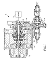
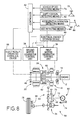
- the hybrid drive system 10 includes: an engine 12 such as an internal combustion engine, which is operated by combustion of a fuel; a damper 14 of spring type adapted to absorb a fluctuation in the rotary motion of the engine 12; a first motor/generator 16; an output member 18; a distributing mechanism 20 of planetary gear type which receives an output of the engine 12 through the damper 14 and which mechanically distributes the received engine output to the first motor/generator 16 and the output member 18; and a second motor/generator 22 whose rotary motion or force is transferred to the output member 18.
- an engine 12 such as an internal combustion engine, which is operated by combustion of a fuel
- a damper 14 of spring type adapted to absorb a fluctuation in the rotary motion of the engine 12
- a first motor/generator 16 an output member 18
- a distributing mechanism 20 of planetary gear type which receives an output of the engine 12 through the damper 14 and which mechanically distributes the received engine output to the first motor/generator 16 and the output
- damper 14, distributing mechanism 20 and first motor/generator 16 are disposed coaxially with each other and are, arranged in the axial direction, while the second motor/generator 22 is disposed coaxially with and radially outwardly of the damper 14 and distributing mechanism 20.
- the distributing mechanism 20 is a single pinion type planetary gear device which includes, as three rotary elements, a sun gear 20s connected to a motor shaft 24 of the first motor/generator 16, a carrier 20c connected to the damper 14, and a ring gear 20r connected to a rotor 22r of the second motor/generator 22.
- the output member 18 is bolted to the rotor 22r of the second motor/generator 22, for rotation with the rotor 22r, and is connected to the ring gear 20r of the distributing mechanism 20 through the rotor 22r.
- the output member 18 has an output gear 26.
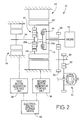
- the output gear 26 is operatively connected to right and left drive wheels of the motor vehicle, through a large gear 30 and a small gear 32 mounted on an intermediate shaft 28, and a differential gear device 34 of bevel gear type, so that a rotary motion of the output shaft 18 is transferred to the drive wheels at a given speed reduction ratio.
- the first motor/generator 16 and the second motor/generator 22 are electrically connected to an electric energy storage device 40 of high-voltage type (e.g., 288V) through a first motor/generator control unit (first M/G control unit) 36 and a second motor/generator control unit (second M/G control unit) 38, respectively.
- first M/G control unit first M/G control unit
- second M/G control unit second M/G control unit
- Each of these first and second motor/generators 16, 22 has a DRIVE state, a CHARGING state, and a NON-LOAD or FREE state, which are selectively established or selected.
- the motor/generator 16, 22 In the DRIVE state, the motor/generator 16, 22 is operated as an electric motor to provide a predetermined torque, with an electric energy being supplied thereto from the storage device 40.
- the motor/generator 16, 22 In the CHARGING state, the motor/generator 16, 22 is operated as an electric generator or dynamo, by regenerative braking (electrical braking torque of the motor/generator per se), so as to charge the storage device 40 with the electric energy.
- the motor/generator 16, 22 In the NON-LOAD or FREE state, the motor/generator 16, 22 is placed in a non-load condition permitting free rotation of the motor shaft 24 and rotor 22r.
- These motor/generators 16, 22 are controlled by the respective first and second M/G control units 36, 38, which in turn are controlled by a controller 42 as indicated in the block diagram of Fig. 3.
- the controller 42 also controls the engine 12, more specifically, the amount of fuel injection, throttle valve opening and ignition timing of the engine 12, to thereby control the operating condition of the engine 12 such as the operating speed and torque.
- the controller 42 includes a microcomputer incorporating a central processing unit (CPU), a random-access memory (RAM) and a read-only memory (ROM).
- the controller 42 is adapted to perform data processing operations according to control programs stored in the ROM, so as to place the present hybrid drive system 10 in a selected one of operating modes which include: a MOTOR DRIVE mode in which only the second motor/generator 22 is operated as a drive power source to drive the vehicle while the first motor/generator 16 is placed in the NON-LOAD state; a CHARGING ⁇ ENGINE DRIVE mode in which only the engine 12 is operated as a drive power source to drive the vehicle while the first motor/generator is operated as an electric generator by the engine 12 to charge the electric energy storage device 40, with the second motor/generator 22 placed in its NON-LOAD state; an ENGINE ⁇ MOTOR DRIVE mode in which the engine 12 and the second motor/generator 22 are operated as drive power sources to drive the vehicle while the first motor/motor 16 is operated
- the CHARGING mode is selected when the vehicle is parked or otherwise stationary.
- the controller 42 is adapted to execute an engine start control routine as illustrated in the flow chart of Fig. 4, as needed, in which the engine 12 is started by the first motor/generator 16, to place the hybrid drive system 10 in the CHARGING mode, for example.
- step S1 The engine start control routine illustrated in the flow chart of Fig. 4 is initiated with step S1 to determine whether an ENGINE START command is present. For instance, this ENGINE START command is generated when the vehicle operator desires to establish the CHARGING mode to charge the electric energy storage device 40 while the vehicle is held stationary. If an affirmative decision (YES) is obtained in step S1, the control flow goes to step S2 to determine whether a PARKING BRAKE switch 44 (Fig. 3) is ON. The PARKING BRAKE switch 44 is turned ON when a parking brake operating member 54 is in an operated position. As indicated in Fig. 3, the parking brake operating member 54 is operated to actuate a parking brake 52 provided for the vehicle wheels for applying parking brake to the vehicle.
- a PARKING BRAKE switch 44 Fig. 3
- the braking brake 52 functions as drive force variation restricting means for restricting a variation in the vehicle drive force due to a reaction force acting on the output member 18 upon starting of the engine 12, more precisely, parking lock means for mechanically locking the vehicle wheels by manipulation of the parking brake operating member 54.
- step S2 If the PARKING BRAKE switch 44 is OFF, that is, if a negative decision (NO) Is obtained in step S2, the control flow goes to step S4 to provide an indication prompting the vehicle operator to operate the parking brake operating member 54 to actuate the parking brake 52. Steps S2 and S4 are repeatedly implemented until an affirmative decision (YES) is obtained in step S2, that is, until the PARKING BRAKE switch 44 is turned ON (i.e., until the parking brake 52 is actuated). When the affirmative decision (YES) is obtained in step S2, the control flow goes to step S3 to operate the first motor/generator 16 for transferring a rotary motion to the engine 12 at rest through the distributing mechanism 20, to thereby start or fire the engine 12.
- An optimum value of the torque or electric current of the first motor/generator 16 upon operation thereof to start the engine 12 is empirically determined by experimentation, so as to permit stable starting or firing of the engine 12, and is stored in a memory device 46 (Fig. 3), so that the first motor/generator 16 is suitably operated in step S3 to start the engine 12. It will be understood that a portion of the controller 42 assigned to implement step S3 of the routine of Fig. 4 constitutes engine starting means for starting the engine 12 by operation of the first motor/generator 16 to crank the engine 12 through the distributing mechanism 20.
- the hybrid drive system 10 of the present first embodiment of the invention is adapted to start the engine 12 by operation of the first motor/generator 16, whereby an engine starter exclusively used for starting the engine 12 is not necessary. Accordingly, the number of the required components of the hybrid drive system 10 is reduced, and the cost of manufacture is accordingly reduced.
- a reaction force may act on the output member 18 due to a resistance (e.g., frictional resistance) to the rotary motion of the engine 12, or the output of the started engine 12 or the output of the first motor/generator 16 may act on the output member 18, whereby there may arise a drive force to move the vehicle upon starting of the engine 12, unexpectedly to the vehicle operator and passengers.
- the first motor/generator 16 is operated in step S3 only when the braking brake 52 is in the operated state. That is, the engine 12 is started by the first motor/generator 16 only when parking brake is applied to the vehicle, so as to prevent unexpected movement of the vehicle upon starting of the engine 12, which would give a discomfort to the vehicle operator and passengers.
- the operation of the parking brake 52 is detected by the PARKING BRAKE switch 44 which is adapted to detect the operated position of the parking brake operating member 54 such as a parking brake lever.
- step S2 of the routine of Fig. 4 may be suitably modified, provided the step is formulated to determine whether parking brake is applied to the vehicle to hold the vehicle stationary.
- the motor vehicle may have a shift lever or other shift position selecting means for placing the hybrid drive system 10 in a selected one of a plurality of positions including a parking position (P) and a drive position (D)
- the motor vehicle may be provided with a mechanical parking lock mechanism which is adapted to lock the power transmission system, more specifically, lock a parking lock gear provided in the power transmission path, when the shift position selecting means is operated to the parking position.
- the PARKING BRAKE switch 44 may be replaced by a detector adapted to detect the activation of the mechanical parking lock mechanism, namely, the operation of the shift position selecting means to the parking position.
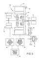
- the ring gear 20r can be locked by using a hydraulically operated friction brake 48 of multiple-disk type as shown in Fig. 5, according to a second embodiment of this invention.
- the friction brake 48 is adapted to fix the output member 18 to a stationary housing 50 of the hybrid drive system 10.
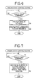
- an engine start control routine illustrated in the flow chart of Fig. 6 is executed. This routine includes does not include a step of determining whether the vehicle is parked with the parking brake 52 in the operated position, but includes step Q2 in which the friction brake 48 is actuated to lock the output member 18 to thereby lock the ring gear 20r.
- Step Q2 is followed by step Q3 similar to step S3, to operate the first motor/generator 16 for starting the engine 12.
- This second embodiment of Figs. 5 and 6 eliminates a need for the vehicle operator to actuate the parking brake 52 by operating the parking brake operating member 54, and thus reduces a load on the vehicle operator.
- This embodiment does not require controlling the second motor/generator 22 so as to hold the vehicle stationary upon starting the engine 12, as in a third embodiment of Fig. 7 which will be described. Accordingly, the engine start control according to the second embodiment of Figs.
- controller 42 assigned to implement step Q3 constitutes engine starting means for starting the engine 12 by operation of the first motor/generator 16 to crank the engine 12 through the distributing mechanism 20, while a portion of the controller 42 assigned to implement step Q2 and the friction brake 48 cooperate to constitute drive force variation restricting means for restricting a variation in the vehicle drive force upon starting of the engine 12, more specifically, engine start braking means for mechanically braking the vehicle wheels prior to starting of the engine 12.
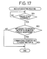
- the third embodiment of Fig. 7 indicated above does not use the friction brake 48, and the engine start control routine does not include a step of determining whether the vehicle is parked, but includes step R2 in which the torque values of the first motor/generator 16 and the second motor/generator 22 are controlled to prevent a movement of the vehicle upon starting of the engine 12. Described in detail, the engine 12 is cranked and started by operation of the first motor/generator 16, while the second motor/generator 22 is controlled to offset a drive force due to a reaction force generated by the operation of the first motor/generator 16 for thereby holding the vehicle stationary upon starting of the engine 12.
- the torque values or electric current values of the motors 16, 22, and the operation timing thereof are empirically determined by experimentation so as to permit stable starting or firing of the engine 12, and are stored in the memory device 46.
- This third embodiment of Fig. 7 adapted to start the engine 12 while holding the vehicle stationary by controlling the first and second motors 16, 22 does not require the vehicle operator to operate the parking brake operating member 54 and accordingly reduces a load on the vehicle operator, whereby the hybrid drive system is simplified and available at a reduced cost owing to the elimination of the friction brake 48.
- controller 42 assigned to implement a part of the step R2 assigned to control the first motor generator 16 constitutes the engine starting means
- a portion of the controller 42 assigned to implement a part of the step R2 assigned to control the second motor/generator 22 constitutes the drive force variation restricting means, more precisely, engine start motor control means for controlling the second motor/generator 22 so as to offset a drive force due to a reaction force generated by the operation of the first motor/generator 16 upon starting of the engine 12 by the engine starting means.
- the third embodiment of Fig. 7 is capable of starting the engine 12 only only when the vehicle is held stationary, but also during running of the vehicle, for example, in the MOTOR DRIVE mode in which only the second motor/generator 22 is operated as the drive power source for driving the vehicle.
- the engine 12 can be started through the distributing mechanism 20, by a regenerative braking torque generated by the first motor/generator during free rotation thereof in the reverse direction, by operating the first motor/generator 16 in the forward direction.
- the second motor/generator 22 is operated so as to produce an output which is larger than the power required to drive the vehicle, so that the engine 12 is cranked for starting by surplus power which is the output of the second motor/generator 22 minus the required power.
- a fourth embodiment of this invention in the form of a hybrid drive system 58 in which the engine 12, first motor/generator 16, distributing mechanism 20 and second motor/generator 22 are operatively connected to each other, as in the first embodiment of Fig. 2.
- the arrangement of these components in the hybrid drive system 58 is different from that in the hybrid drive system 10 of the first embodiment. Described more specifically, the first motor/generator 16 and the second motor/generator 22 are disposed on the axially opposite sides of the distributing mechanism 20, and the damper 14 and the engine 12 are disposed on one side of the first motor/generator 16 which is remote from the distributing mechanism 20.
- a sprocket 60 integrally connected to the ring gear 20r.
- the sprocket 60 is connected to a speed reducer 64 through a chain 62.
- the sprocket 60 functions as an output member operatively connected to the vehicle drive wheels.
- the speed reducer 64 is of parallel 2-axes type having a rotary shaft 66 which is provided with a parking lock gear 70 of a mechanical parking lock mechanism 68.
- shift position selecting means in the form of a shift lever 72 is operated to a parking position (P)
- a parking lock pawl 74 of the parking lock mechanism 68 is brought into engagement with the parking lock gear 70, thereby locking the rotary shaft 66, and consequently locking the differential gear device 34 connected to the rotary shaft 66 through gears, whereby vehicle drive wheels 76 are locked.
- the parking lock pawl 74 is mechanically connected to the shift lever 72 through a cable and a link mechanism, so that a pivotal movement of the shift lever 72 causes a pivotal movement of the parking lock pawl 74 for engagement with the parking lock gear 70 connected to the rotary shaft 66 of the speed reducer 64.
- the controller 42 receives output signals of vehicle speed detecting means 78, accelerator operation detecting means 82 and SOC detecting means 84.
- the output signals of the detecting means 78, 80, 82, 84 respectively represent a vehicle running speed V, a currently selected position of the shift lever 72 (of the hybrid drive system 58), an amount of operation of an accelerator pedal 86 and an amount of electric energy SOC stored in the electric energy storage device 40.
- the vehicle speed detecting means 78 may be adapted to detect the rotating speed of a selected rotary member such as the second motor/generator 22, which can be used to calculate the vehicle running speed V.
- the shift lever 72 has a plurality of operating positions including the above-indicated parking position (P), a forward-drive position (D), a reverse-drive position (R), and a neutral position (N) in which the hybrid drive system 58 does not provide a drive force in principle.
- the accelerator operation detecting means 82 generates an idling signal as well as the signal representative of the operation amount of the accelerator pedal 86 (which represents the output of the hybrid drive system 58 currently required by the vehicle operator).
- the idling signal is generated when the operation amount of the accelerator pedal 86 is zero, namely, when the hybrid drive system 58 is in an idling state.
- the controller 42 controls the motor/generator 16 and motor/generator 22 through the respective M/G control units 36, 38, so as to start the engine 12.
- the friction brake 48 may be provided on a suitable rotary member which rotates with the drive wheels 76 or idler wheels.
- the friction brake 48 may be provided on the speed reducer 64.
- the friction brake 48 may be replaced by replaced by wheel brakes 90 generally provided for braking the drive wheels 76 or idler wheels of the vehicle.
- step SA1 determines whether the ENGINE START command is present. If an affirmative decision (YES) is obtained in step SA1, the control flow goes to step SA2 to determine whether the shift lever 72 is placed in the parking position (P). This determination is effected on the basis of the output signal of the shift position detecting means 80. If an affirmative decision (YES) is obtained in step SA2, the control flow goes to step SA3 similar to step S3, to operate the first motor/generator 16 for cranking and starting (firing) the engine 12.
- step SA3 a portion of the controller 42 assigned to implement step SA3 constitutes the engine starting means, while the mechanical parking lock mechanism 68 functions as the drive force variation restricting means, and more specifically, the parking lock means for mechanically locking the vehicle wheels.
- step SA2 If a negative decision (NO) is obtained in step SA2, the control flow goes to step SA4 to determine whether the shift lever 72 is placed in the neutral position (N). If an affirmative decision (YES) is obtained in step SA4, step SA5 is implemented to determine whether the vehicle running speed V is equal to or lower than a predetermined first threshold V1. This determination is effected based on the output signal of the vehicle speed detecting means 78. If an affirmative decision (YES) is obtained in step SA5, the control flow goes to step SA6 to actuate the hydraulic device 88 for delivering a pressurized working fluid to the friction brake 48 for engagement thereof. Then, step SA3 is implemented to start the engine 12.
- step SA5 If a negative decision (NO) is obtained in step SA5, the control flow goes directly to step SA3 while skipping step SA6.
- the friction brake 48 may be relatively rapidly engaged in step SA6 if the vehicle speed V is substantially or close to zero.
- step SA6 is preferably formulated to slowly raise the pressure of the working fluid to be delivered to the friction brake 48 if the vehicle speed V is relatively high (if the vehicle is coating at a relatively high speed with the shift lever 74 placed in the neutral position), so that the friction brake 48 is relatively slowly engaged to prevent a shock due to an abrupt brake by engagement of the friction brake 48.
- the second motor/generator cannot be operated to offset a drive force due to the operation of the first motor/generator 16 to start the engine 12.
- the friction brake 48 is engaged to stop the vehicle in step SA6, before the engine 12 is started in step SA3, so that the vehicle is prevented from moving by a drive force generated upon starting of the engine 12, unexpectedly to the vehicle operator.
- the vehicle speed V is higher than the first threshold V1, that is, when the vehicle is coating at a relatively high speed, the engine 12 is started during running of the vehicle.
- the vehicle drive force may vary upon starting of the engine 12, but the drive force variation during running of the vehicle will give a smaller degree of discomfort to the vehicle operator than when the vehicle is stationary or the vehicle speed V is considerably low (i.e., not higher than the first threshold V1).
- the first threshold V1 is determined to prevent or absorb a vehicle drive force variation due to starting of the engine 12 during running of the vehicle, which would give a considerable degree of discomfort to the vehicle operator.
- a portion of the controller 42 assigned to implement step SA6 constitutes the drive force variation restricting means, and more precisely, the engine start braking means, and that a portion of the controller 42 assigned to implement step SA5 constitutes inhibiting means for inhibiting an operation of the drive force variation restricting means when the vehicle speed is higher than a predetermined threshold.
- step SA4 If a negative decision (NO) is obtained in step SA4, that is, the shift lever 72 is placed in the forward-drive position (D) or reverse-drive position (R), the control flow goes to step SA7 to determine whether the vehicle speed V obtained from the output signal of the vehicle speed detecting means 78 is equal to or lower than a predetermined second threshold V2. If an affirmative decision (YES) is obtained in step SA7, step SA8 is implemented to determine whether the hybrid drive system 58 is placed in the idling state, that is, whether the operation amount of the accelerator pedal 86 represented by the output signal of the accelerator operation detecting means 82 is substantially zero.
- step SA6 If the vehicle speed V is not higher than the second threshold V2 and the operation amount of the accelerator pedal 86 is substantially zero, the friction brake 48 is engaged in step SA6 before the engine 12 is started in step SA3. If the vehicle speed V is higher than the second threshold V2 or the accelerator pedal 86 is depressed, the control flow goes to step SA9 to operate the second motor/generator 22 so as to absorb or prevent a variation in the vehicle drive force due to the starting of the engine 12 in step SA3.
- step SA9 constitutes the drive force variation restricting means, more precisely, engine start motor control means for controlling the second motor/generator 22 so as to offset a drive force due to a reaction forge generated by the operation of the first motor/generator 16 upon starting of the engine 12.
- Step SA9 is implemented contemporaneously with step SA3, so that the first motor/generator 16 and the second motor/generator 22 are simultaneously controlled to start the engine 12 without a considerably vehicle drive force variation.
- the vehicle speed V is not higher than the predetermined second threshold V2, that is, when the vehicle is stationary or running at a low speed, and when the accelerator pedal 86 is not depressed; the vehicle is stopped by operation of the friction brake 48 in step SA6 before the engine 12 is started, so as to prevent a movement of the vehicle by a drive force generated upon starting of the engine 12, unexpectedly to the vehicle operator.
- the vehicle speed V is higher than the second threshold V2, or when the accelerator pedal 86 is depressed, the engine 12 is started without operation of the friction brake 48, but the second motor/generator 22 is operated to absorb or prevent a vehicle drive force variation due to starting of the engine 12 by operation of the first motor/generator 16. Accordingly, the engine 12 can be started without giving a discomfort to the vehicle operator.
- the second threshold V2 may be lower than the first threshold V1.
- a hybrid drive system 100 constructed according to a fifth embodiment of the present invention, which is provided with an engine starter motor 102 connected to a crankshaft of the engine 12, so that the engine 12 can be started by the engine starter motor 102, without a rotary motion being transferred to the engine 12 through the distributing mechanism 20.
- the engine starter motor 102 is powered by an electric energy storage device 104 of low-voltage type (e.g. 12V) generally provided on a common engine-driven vehicle as a power source for starting the engine.
- an electric energy storage device 104 of low-voltage type (e.g. 12V) generally provided on a common engine-driven vehicle as a power source for starting the engine.
- the storage device 104 has external terminals provided for easy connection through a booster cable to an electric energy storage device (battery) provided on a common engine-drive vehicle, when the electric energy stored in the storage device 104 is not sufficient for operating the engine starter motor 102 to start the engine 12. Since the engine 12 can thus be started by the motor starter motor 102, the high-voltage type electric energy storage device 40 can be charged by operation of the first motor/generator 16 by the engine 12, even when the storage device 104 is not initially sufficiently charged. If the high-voltage type storage device 40 is not charged enough to operate the first motor/generator 16 to start the engine 12, the storage device 40 cannot be charged by operation of the first motor/generator 16 by the engine 12 since the engine 12 cannot be started.
- an electric energy storage device battery
- the high-voltage storage device 40 should be charged by a special device for high-voltage application.
- the low-voltage storage device 104 is connected to the first motor/generator 16 and the high-voltage storage device 40 through a suitable voltage converter device, so that the electric energy may be supplied between the storage devices 40, 104.
- the storage device 104 may be used for an optionally provided device such as an air conditioner.
- the engine 12 is started by the engine starter motor 102 while the first motor/generator 16 is placed in the NON-LOAD or FREE state.
- the engine 12 can be started without a vehicle drive force variation, at any time except when the first motor/generator 16 is in a motoring state in which the first motor/generator 16 is operated to prevent excessive rotation of the pinion of the distributing mechanism 20 during running of the vehicle in the forward-drive position (D).
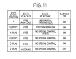
- Table in Fig. 11 indicates operating states of the first motor/generator 16, second motor/generator 22 and engine starter motor 102 when the engine 12 is started in different running conditions of the vehicle with the shift lever placed in the parking, neutral and forward-drive positions (P, N, D).
- an indication "NO SPECIAL CONTROL" of the second motor/generator 22 means that no special control of the second motor/generator 22 is required for starting the engine 12.
- step SB1 similar to step S1, to determine whether the ENGINE START command is present. If an affirmative decision (YES) is obtained in step SB1, the control flow goes to step SB2 to determine whether the first motor/generator 16 is in the motoring state. If an affirmative decision (YES) is obtained in step SB2, it means that the engine 12 is running without combustion of a fuel. In this case, the routine is terminated. If a negative decision (NO) is obtained in step SB2, that is, if the first motor/generator 16 is in the NON-LOAD or FREE state, the control flow goes to step SB3 to operate the engine starter motor 102 to crank and start the engine 12.
- NO negative decision
- the engine 12 is started by the engine starter motor 102 while the first motor/generator 16 is in the NON-LOAD or FREE state, so that the first motor/generator 16 is rotated with a rotary motion of the engine 12, whereby a drive force will not be transferred to the output member 18 and the vehicle drive wheels.
- the engine 12 can be started by the engine starter motor 102, without a vehicle drive force variation unexpected to the vehicle operator, when the vehicle is running as well when the vehicle is stopped or parked.
- step SB3 a portion of the controller 42 assigned to implement step SB3 constitutes the engine starting means.
- the engine 12 can be started by using both the engine starter motor 102 and the first motor/generator 16. In this case, however, it is desirable to prevent a vehicle drive force variation by holding the vehicle stationary by actuating the parking brake 52, mechanical parking lock mechanism 68 or friction brake 48, as provided in the preceding embodiments, or by operating the second motor/generator 22 so as to prevent or absorb the vehicle drive force variation.
- the hybrid drive system 100 may be adapted to normally use predetermined one of the engine starter motor 102 and the first motor/generator 16, and to use the other alone or use both of the engine starter motor 102 and the first motor/generator 16 if the engine 12 cannot be started by the predetermined one of the engine starter motor 102 and the first motor/generator 16.
- the capacity and size of the engine starter motor 102 can be reduced for reducing the cost and the required installation space, provided that the engine starter motor 102 is able to start the engine 12, which is then used to operate the first motor/generator 16 for charging the storage device 40.
- the engine starter motor 102 can be operated by an electric energy supplied from another vehicle.
- a hybrid drive system 110 according to a sixth embodiment of this invention.
- This hybrid drive system 110 is identical with the hybrid drive system of the second embodiments of Figs. 5 and 6, except for a clutch 112 disposed between the intermediate shaft 28 and the small gear 32 for selective connection and disconnection therebetween.
- Table of Fig. 14 indicates the operating states of the first motor/generator 16, second motor/generator 22 and clutch 112 when the engine 12 is started in the different positions (P, N, D) of the shift lever.
- the engine 12 is started according to an engine start control routine illustrated in the flow chart of Fig. 15.
- the second motor/generator 22 is held in an active state even when the shift lever is placed in the parking or neutral position (P, N). Therefore, the torque of the second motor/generator 22 can be controlled by regulating the electric current, for example, even in the parking or neutral position (P, N), as in the forward-drive position (D).
- step SC1 The engine start control routine of Fig. 15 is initiated with step SC1 similar to step S1, to determine whether the ENGINE START command is present. If an affirmative decision (YES) is obtained in step SC1, the control flow goes to step SC2 to determine whether the shift lever is placed in the parking or neutral position (P, N). If an affirmative decision (YES) is obtained in step SC2, step SC3 is implemented to release the clutch 112 for disconnection of the power transmitting path, and then step SC4 is implemented to control the outputs of the first motor/generator 16 and the second motor/generator 22, for starting the engine 12. In this case, the first motor/generator 16 and the second motor/generator 22 are controlled in one of three modes as indicated in Fig. 14.
- the first motor/generator 16 and the second motor/generator 22 are both operated in the forward direction.
- the first motor/generator 16 is operated in the forward direction, while the second motor/generator 22 is controlled (e.g., by regenerative braking) to be locked.
- the second motor/generator 22 is operated in the forward direction, while the first motor/generator 16 is controlled (e.g., by regenerative braking) to be locked.
- the vehicle is generally stationary with the shift lever placed in the neutral or parking position.
- the engine 12 is started by first releasing the clutch 112 to disconnect the power transmitting path, and then controlling the first motor/generator 16 and the second motor/generator 22, so that the engine 12 can be started without a vehicle drive force variation unexpected to the vehicle operator.
- controller 42 assigned to implement steps SC3 and SC4 constitutes the engine starting means.
- step SC2 If a negative decision (NO) is obtained in step SC2, the control flow goes to step SC4 to determine whether the shift lever is placed in the forward-drive position. If an affirmative decision (YES) is obtained in step SC5, step SC6 is implemented to engage the clutch 112 for connecting the power transmitting path, and step SC7 is then implemented to operate the first motor/generator 16 in the forward direction to start the engine 12.
- step SC5 an affirmative decision obtained in step SC5
- step SC6 is implemented to engage the clutch 112 for connecting the power transmitting path
- step SC7 is then implemented to operate the first motor/generator 16 in the forward direction to start the engine 12.
- the forward rotation of the first motor/generator 16 is interpreted to include application of a forward torque or a regenerative braking torque to the first motor/generator 16 during reverse rotation thereof.
- Step SC7 may be modified to control the torque of the second motor/generator 22 so as to absorb a vehicle drive force variation upon starting of the engine 12, as in step SA9 in the fourth embodiment of Figs. 8 and 9.
- the content of step SC7 may be changed depending upon whether the vehicle is stationary or running. Further, the engine 12 may be started with the clutch 112 placed in the released position, even when the shift lever is in the forward-drive position, as in the neutral or parking position.
- the clutch 112 is preferably a hydraulically operated friction clutch. However, the clutch 112 may use an axially sliding member for connecting and disconnecting two gears. The clutch 112 may be disposed at any suitable position in the power transmitting path between the output member 18 and the vehicle drive wheels, for example, between the intermediate shaft 28 and the large gear 30, or between the output member 18 and the output gear 26.
- a hybrid drive system 120 according to a seventh embodiment of the invention will be described by reference to Figs. 16 and 17.
- the hybrid drive system 120 includes the engine starter motor 102 as provided in the hybrid drive system 100 of Fig. 10 and the clutch 112 as provided in the hybrid drive system 110 of Fig. 13.
- a motor assisting routine illustrated in the flow chart of Fig. 17 is executed prior to an engine start control routine, which is identical with the routine of Fig. 15 except for the elimination of step SC1.
- This motor assisting routine is initiated with step SD1 to determine whether the ENGINE START command is present.
- step SD1 If an affirmative decision (YES) is obtained in step SD1, the control flow goes to step SD2 to determine whether the first motor/generator 16 cannot be operated due to insufficient electric energy stored in the storage device 40, or the torque of the motor/generator 16 is insufficient. If a negative decision (NO) is obtained in step SD2, the control flow goes directly to step SC2 of the engine start control routine. If an affirmative decision (YES) is obtained in step SD2, the control flow goes to step SD3 to generate a command to operate the engine starter motor 102 to assist the first motor/generator 16 in step SC4 or SC7.
- controller 42 assigned to implement steps SD2 and SD3 constitutes motor assisting means for operating the engine starter motor 102 to assist the motor/generator 16 and motor/generator 22 for starting the engine 12 when the vehicle is in a predetermined condition, namely, when the engine 12 cannot be started by the first motor first motor/generator 16.
- the present seventh embodiment may be adapted to release the clutch 112 when the shift lever is placed in the neutral or parking position (N, P), and engage the clutch when the shift lever is placed in the forward-drive position (D), as in the sixth embodiment of Figs. 13-15, and start the engine 12 by using the engine starter motor 102 except when the first motor/generator 16 is in the motoring state, as in the fifth embodiment of Figs. 10-12.
- the first motor/generator 16 and the second motor/generator 22 may be controlled as indicated in Fig. 11 or 14.
- the hybrid drive system according to the invention may include any other power transmitting mechanism or mechanisms, for example, a transmission having a plurality of speed rations, such as parallel two-axes type or planetary gear type transmission, or a continuously variable transmission such as a belt-and-pulley type transmission, and/or a forward-reverse switching mechanism having forward-drive and reverse-drive positions.
- a transmission having a plurality of speed rations such as parallel two-axes type or planetary gear type transmission
- a continuously variable transmission such as a belt-and-pulley type transmission
- a forward-reverse switching mechanism having forward-drive and reverse-drive positions.
- first motor/generator may be modified as needed.
Description
Claims (8)
- A hybrid drive system for a motor vehicle, including:an engine (12) operated by combustion of a fuel,a first motor/generator (16),a distributing mechanism (20) for mechanically distributing an output of said engine (12) to said first motor/generator (16) and an output member (18, 60),a second motor/generator (22) whose rotary force is transferred to the output member (18, 60),engine starting means (42, S3, Q3, R2, SA3, SC4) for operating at least one of said first motor/generator (16) and said second motor/generator (22) to crank said engine (12) through said distributing mechanism (20), for thereby starting said engine (12), anddrive force variation restricting means (42, 48, 52, 68, 112, Q2, R2, SA6, SA9, SC3) for restricting a variation in a vehicle drive force due to a reaction force which acts on said output member (18, 60) upon starting of said engine (12) by said engine starting means (42, Q3, R2, SA3, SC4),said hybrid drive system being characterized in thatsaid output member is operatively connected to a drive wheel (76) of the motor vehicle so that the drive wheel is driven by the output member (18, 60), andsaid distributing mechanism (20) is a gear type mechanism having three rotary members, a first rotary member (20s) being connected to said first motor/generator (16), a second rotary member (20c) being connected to said engine (12) and a third rotary member (20r) being connected to said second motor/generator (22).
- A hybrid drive system according to claim 1, wherein said drive force variation restricting means comprises parking lock means (52, 68) for mechanically locking said drive wheel (76) by manipulation of an operator's controlled operating member (54, 72).
- A hybrid drive system according to claim 1, wherein said drive force variation restricting means comprises engine start motor control means (42, R2, SA9) for controlling said second motor/generator (22) so as to offset said variation in the vehicle drive force upon starting of said engine (12) by said engine starting means (42, R2, SA3).
- A hybrid drive system according to claim 1, wherein said drive force variation restricting means comprises engine start braking means (42, 48, Q2, SA6) for automatically mechanically braking said drive wheel (76) prior to starting of said engine (12) by said engine starting means (42, Q2, SA3).
- A hybrid drive system according to any one of claims 2 to 4, wherein means (42, SA5) is provided for inhibiting an operation of said drive force variation restricting means (42, 48, 52, 68, Q2, R2, SA6, SA9) when a running speed of the motor vehicle is higher than a predetermined threshold.
- A hybrid drive system according to claim 1, wherein said drive force variation restricting means comprises:a clutch (112) disposed between said output member (18) and said drive wheel and having an engaged position for connecting said output member to said drive wheel and a released position for disconnecting said drive wheel from said output member; andclutch releasing means (42, SC3) for automatically placing said clutch in said released position before said engine starting means (42, SC4) operates at least one of said first motor/generator (16) and said second motor/generator (22) to crank said engine (12)
- A hybrid drive system according to claim 6, further comprising an engine starter motor (102) for starting said engine (12), and motor assisting means (42, SD2, SD3) for operating said engine starter to assist said at least one of said first motor/generator (16) and said second motor/generator (22) to start said engine (12) when said at least one of said first motor/generator (16) and said second motor/generator (22) is in a predetermined condition.
- A hybrid drive system according to claim 7, wherein said motor assisting means operates said engine starter motor (102) when said engine (12) cannot be started by said at least one of said first motor/generator (16) and said second motor/generator (22).
Applications Claiming Priority (6)
| Application Number | Priority Date | Filing Date | Title |
|---|---|---|---|
| JP26892295 | 1995-10-18 | ||
| JP26892295 | 1995-10-18 | ||
| JP268922/95 | 1995-10-18 | ||
| JP235063/96 | 1996-09-05 | ||
| JP23506396 | 1996-09-05 | ||
| JP23506396A JP3129204B2 (en) | 1995-10-18 | 1996-09-05 | Hybrid drive |
Publications (3)
| Publication Number | Publication Date |
|---|---|
| EP0769403A2 EP0769403A2 (en) | 1997-04-23 |
| EP0769403A3 EP0769403A3 (en) | 1997-09-03 |
| EP0769403B1 true EP0769403B1 (en) | 2000-05-10 |
Family
ID=26531930
Family Applications (1)
| Application Number | Title | Priority Date | Filing Date |
|---|---|---|---|
| EP96116592A Expired - Lifetime EP0769403B1 (en) | 1995-10-18 | 1996-10-16 | Hybrid vehicle drive system having two motor generator units and engine starting means |
Country Status (4)
| Country | Link |
|---|---|
| US (1) | US5934395A (en) |
| EP (1) | EP0769403B1 (en) |
| JP (1) | JP3129204B2 (en) |
| DE (1) | DE69608200T2 (en) |
Cited By (3)
| Publication number | Priority date | Publication date | Assignee | Title |
|---|---|---|---|---|
| US6862887B2 (en) | 2001-11-03 | 2005-03-08 | Daimler Chrysler Ag | Hybrid drive |
| US8763578B2 (en) | 2010-09-29 | 2014-07-01 | Bayersiche Motoren Werke Aktiengesellschaft | Vehicle drive having at least two starting systems |
| WO2016133453A1 (en) * | 2015-02-18 | 2016-08-25 | Scania Cv Ab | Method and control system for charging a hybrid vehicle |
Families Citing this family (170)
| Publication number | Priority date | Publication date | Assignee | Title |
|---|---|---|---|---|
| JP3042342B2 (en) * | 1994-12-28 | 2000-05-15 | 株式会社エクォス・リサーチ | Hybrid vehicle |
| AU9659898A (en) * | 1997-10-21 | 1999-05-10 | Stridsberg Innovation Ab | A hybrid powertrain |
| JP3374734B2 (en) * | 1997-12-09 | 2003-02-10 | トヨタ自動車株式会社 | Internal combustion engine control device for hybrid vehicle |
| JP3454133B2 (en) * | 1998-01-16 | 2003-10-06 | トヨタ自動車株式会社 | Drive control device for hybrid vehicle |
| DE19803160C1 (en) * | 1998-01-28 | 1999-05-12 | Daimler Chrysler Ag | Hybrid drive for motor vehicle with IC engine |
| US6232733B1 (en) | 1998-07-28 | 2001-05-15 | Denso Corporation | Engine-motor hybrid vehicle control apparatus and method having power transmission device operation compensation function |
| GB2340463A (en) * | 1998-08-13 | 2000-02-23 | Rover Group | A vehicle with a parallel hybrid powertrain |
| FR2782958B1 (en) * | 1998-09-05 | 2005-11-04 | Mannesmann Sachs Ag | DRIVE SYSTEM FOR A MOTOR VEHICLE WITH INTERNAL COMBUSTION ENGINE AND ELECTRIC MOTOR |
| DE19841828C2 (en) * | 1998-09-12 | 2002-05-29 | Daimler Chrysler Ag | Hybrid drive, especially for vehicles |
| US6554088B2 (en) | 1998-09-14 | 2003-04-29 | Paice Corporation | Hybrid vehicles |
| WO2000015455A2 (en) * | 1998-09-14 | 2000-03-23 | Paice Corporation | Hybrid vehicles |
| US6209672B1 (en) * | 1998-09-14 | 2001-04-03 | Paice Corporation | Hybrid vehicle |
| US6338391B1 (en) | 1999-03-01 | 2002-01-15 | Paice Corporation | Hybrid vehicles incorporating turbochargers |
| JP3414310B2 (en) * | 1998-09-25 | 2003-06-09 | トヨタ自動車株式会社 | Engine start control device |
| FR2783763B1 (en) | 1998-09-30 | 2000-11-17 | Renault | MOTOR-PROPELLER GROUP COMPRISING A TORQUE AND SPEED CONTROLLED HEAT MOTOR |
| FR2783764B1 (en) | 1998-09-30 | 2000-11-17 | Renault | HYBRID DRIVE GROUP WITH DIRECT DRIVE |
| JP3719339B2 (en) * | 1998-11-09 | 2005-11-24 | 日産自動車株式会社 | Variable valve controller for internal combustion engine |
| WO2000032433A1 (en) * | 1998-12-01 | 2000-06-08 | Hitachi, Ltd. | Drive device and vehicle |
| SE514510C2 (en) * | 1998-12-08 | 2001-03-05 | Abb Ab | Hybrid drive device and wheeled vehicles equipped with a hybrid drive device |
| JP3456159B2 (en) * | 1999-01-29 | 2003-10-14 | 三菱自動車工業株式会社 | Hybrid car |
| JP3558264B2 (en) | 1999-03-29 | 2004-08-25 | 株式会社日立ユニシアオートモティブ | Electric generator unit |
| DE10018926A1 (en) * | 1999-04-26 | 2000-11-02 | Luk Lamellen & Kupplungsbau | Drive train, especially for motor vehicle, has at least one gearbox component that implements transmission function mounted radially within rotor |
| DE50013567D1 (en) | 1999-06-21 | 2006-11-16 | Manfred Schroedl | ELECTRICAL MACHINE |
| DE19934696A1 (en) | 1999-07-23 | 2001-05-17 | Zahnradfabrik Friedrichshafen | Electrodynamic drive system |
| JP4069556B2 (en) * | 1999-10-07 | 2008-04-02 | トヨタ自動車株式会社 | Control method for power output device |
| JP3553437B2 (en) * | 1999-10-19 | 2004-08-11 | ジヤトコ株式会社 | Electric torque converter |
| JP3410056B2 (en) * | 1999-11-19 | 2003-05-26 | トヨタ自動車株式会社 | Vehicle engine start control device |
| JP3909644B2 (en) * | 1999-12-27 | 2007-04-25 | アイシン・エィ・ダブリュ株式会社 | Hybrid drive device |
| JP4636651B2 (en) * | 2000-04-07 | 2011-02-23 | Gknドライブラインジャパン株式会社 | Power transmission device |
| JP3562432B2 (en) * | 2000-04-12 | 2004-09-08 | 日産自動車株式会社 | Automatic restart / restart system for vehicle engines |
| US6307277B1 (en) * | 2000-04-18 | 2001-10-23 | General Motors Corporation | Apparatus and method for a torque and fuel control system for a hybrid vehicle |
| FR2809058A1 (en) * | 2000-05-17 | 2001-11-23 | Timothee Biel | Progressive transmission for hybrid automobile in which use of thermal engine is limited to reduce fuel consumption and toxic emissions and to allow short journeys by means of the electric drive only |
| JP3844110B2 (en) * | 2000-06-12 | 2006-11-08 | アイシン・エィ・ダブリュ株式会社 | Hybrid drive device |
| EP1300587B1 (en) | 2000-07-11 | 2010-10-06 | Aisin Aw Co., Ltd. | Hybrid drive device |
| JP4144172B2 (en) * | 2000-09-29 | 2008-09-03 | マツダ株式会社 | Hybrid drive device |
| JP2002195137A (en) | 2000-12-27 | 2002-07-10 | Aisin Aw Co Ltd | Hybrid vehicle and control method for the same |
| US20040174125A1 (en) * | 2000-12-27 | 2004-09-09 | Transportation Techniques Llc | Method and apparatus for adaptive control of hybrid electric vehicle components |
| JP2002211258A (en) * | 2001-01-17 | 2002-07-31 | Unisia Jecs Corp | Power transmission device |
| US6603215B2 (en) * | 2001-05-24 | 2003-08-05 | Ford Global Technologies, Llc | Hybrid electric vehicle control strategy while traveling in reverse |
| FR2828140B1 (en) | 2001-07-31 | 2003-10-03 | Renault | HYBRID DRIVE GROUP COMPRISING A LOCKABLE EPICYCLOIDAL TRAIN |
| JP3651425B2 (en) * | 2001-08-28 | 2005-05-25 | トヨタ自動車株式会社 | Power output apparatus and hybrid vehicle equipped with the same |
| JP4445166B2 (en) * | 2001-09-11 | 2010-04-07 | ヤンマー株式会社 | Ship power generation propulsion device |
| JP3852321B2 (en) * | 2001-10-22 | 2006-11-29 | トヨタ自動車株式会社 | HV drive structure and method with cranking support torque increasing means |
| FR2832356A1 (en) | 2001-11-16 | 2003-05-23 | Timothee Biel | Hybrid drive motor vehicle has epicyclic planetary gear train connected to motor-brake |
| ITBO20010734A1 (en) * | 2001-11-30 | 2003-05-30 | New Holland Italia Spa | HYBRID PROPULSION GROUP FOR AGRICULTURAL TRACTORS |
| DE10160481A1 (en) * | 2001-12-08 | 2003-06-18 | Bosch Gmbh Robert | Method for starting an internal combustion engine of a hybrid drive of a motor vehicle |
| ATE393046T1 (en) | 2001-12-26 | 2008-05-15 | Toyota Motor Co Ltd | DRIVE DEVICE OF A HYBRID VEHICLE |
| JP3585121B2 (en) * | 2002-02-20 | 2004-11-04 | トヨタ自動車株式会社 | Power output device and automobile equipped with the same |
| US6781252B2 (en) * | 2002-03-14 | 2004-08-24 | Ford Global Technologies, Llc | Method and apparatus for starting an engine using a starter/alternator and an accessory drive |
| DE10249621A1 (en) * | 2002-10-21 | 2004-04-29 | Volkswagen Ag | Process and device to reduce shut off impacts in a combustion engine connected to an electrical machine produces temporary opposing moment through the electrical machine |
| JP3958220B2 (en) | 2003-01-16 | 2007-08-15 | 株式会社豊田中央研究所 | Torque transmission device |
| JP4130155B2 (en) * | 2003-05-29 | 2008-08-06 | トヨタ自動車株式会社 | Vehicle drive device |
| SE526946C2 (en) * | 2003-06-13 | 2005-11-22 | Haldex Brake Prod Ab | Sensor system |
| JP3963868B2 (en) * | 2003-06-23 | 2007-08-22 | トヨタ自動車株式会社 | Control device for hybrid drive |
| US6941198B2 (en) * | 2003-09-10 | 2005-09-06 | Ford Motor Company | Method for controlling activation of a power source of a hybrid electric vehicle |
| DE10353256B3 (en) * | 2003-11-14 | 2005-03-31 | Barske, Heiko, Dr. | Automobile hybrid drive system with common control of converter unit between electrical machine driven by IC engine and electrical energy store and clutches on input and output sides of electrical machine |
| JP3986494B2 (en) * | 2003-12-02 | 2007-10-03 | アイシン・エィ・ダブリュ株式会社 | Hybrid drive device and automobile equipped with hybrid drive device |
| JP3783716B2 (en) * | 2004-01-22 | 2006-06-07 | トヨタ自動車株式会社 | Control device for hybrid vehicle |
| JP3783714B2 (en) * | 2004-01-22 | 2006-06-07 | トヨタ自動車株式会社 | Control device for hybrid vehicle |
| JP3783715B2 (en) * | 2004-01-22 | 2006-06-07 | トヨタ自動車株式会社 | Control device for hybrid vehicle |
| DE102004010111A1 (en) * | 2004-02-27 | 2005-07-28 | Rainer Pfalz | Infinitely variable splitting tandem-automatic drive, comprising two or more drive units working individually or in combination |
| JP4111156B2 (en) | 2004-03-12 | 2008-07-02 | アイシン・エィ・ダブリュ株式会社 | Drive control device, drive control method, and program |
| JP4111155B2 (en) | 2004-03-12 | 2008-07-02 | アイシン・エィ・ダブリュ株式会社 | Drive control device, drive control method, and program |
| US8827091B2 (en) * | 2004-03-31 | 2014-09-09 | Kobelco Cranes Co., Ltd. | Crane and method of assembling crane |
| US7214156B2 (en) * | 2004-06-18 | 2007-05-08 | Eaton Corporation | Start and operation sequences for hybrid motor vehicles |
| US7465251B2 (en) * | 2004-07-10 | 2008-12-16 | Lingling Zhang | Hybrid electric vehicle |
| US20060047400A1 (en) * | 2004-08-25 | 2006-03-02 | Raj Prakash | Method and apparatus for braking and stopping vehicles having an electric drive |
| JP4165480B2 (en) | 2004-09-08 | 2008-10-15 | トヨタ自動車株式会社 | Automobile and control method thereof |
| JP3998016B2 (en) * | 2004-11-12 | 2007-10-24 | トヨタ自動車株式会社 | Vehicle drive device |
| US7311163B2 (en) * | 2004-11-16 | 2007-12-25 | Eaton Corporation | Regeneration and brake management system |
| JP4244915B2 (en) * | 2004-11-22 | 2009-03-25 | トヨタ自動車株式会社 | Vehicle drive device |
| JP4259494B2 (en) | 2005-03-04 | 2009-04-30 | トヨタ自動車株式会社 | Control device for vehicle drive device |
| JP4667090B2 (en) * | 2005-03-16 | 2011-04-06 | ヤマハ発動機株式会社 | Hybrid vehicle drive unit, hybrid vehicle and motorcycle |
| JP4406883B2 (en) * | 2005-03-25 | 2010-02-03 | スズキ株式会社 | Drive device for hybrid vehicle |
| US7832297B2 (en) | 2005-04-19 | 2010-11-16 | Hewatt Chris B | Method and apparatus for gyroscopic propulsion |
| FR2885106B1 (en) * | 2005-05-02 | 2007-08-10 | Peugeot Citroen Automobiles Sa | METHOD FOR BLOCKING WHEELS OF A HYBRID VEHICLE AT STOPPING AND TRANSMISSION DEVICE THEREFOR |
| US7512466B2 (en) * | 2005-06-30 | 2009-03-31 | Honeywell International Inc. | High-torque, low power reaction wheel array and method |
| JP4239102B2 (en) * | 2005-07-05 | 2009-03-18 | アイシン・エィ・ダブリュ株式会社 | Hybrid vehicle drive system |
| JP4222349B2 (en) * | 2005-08-25 | 2009-02-12 | トヨタ自動車株式会社 | Hybrid vehicle and control method thereof |
| DE102005044181A1 (en) * | 2005-09-15 | 2007-04-19 | Deere & Company, Moline | Drive system for a vehicle and an agricultural utility vehicle |
| DE102005046617A1 (en) * | 2005-09-29 | 2007-04-12 | Zf Friedrichshafen Ag | Drive unit with nested electric motors |
| JP4337797B2 (en) * | 2005-09-29 | 2009-09-30 | トヨタ自動車株式会社 | Power control device and electric vehicle |
| US7448458B2 (en) * | 2005-10-04 | 2008-11-11 | John Fred Meyer | Electric vehicle reaction drive |
| KR100680790B1 (en) | 2005-11-28 | 2007-02-08 | 현대자동차주식회사 | Power transmit system for hybrid vehicle |
| JP4352269B2 (en) * | 2005-12-05 | 2009-10-28 | スズキ株式会社 | Hybrid drive device |
| JP4349400B2 (en) | 2006-02-28 | 2009-10-21 | トヨタ自動車株式会社 | Vehicle and control method thereof |
| JP4328976B2 (en) * | 2006-03-20 | 2009-09-09 | 三菱ふそうトラック・バス株式会社 | Control device for hybrid electric vehicle |
| US7797089B2 (en) * | 2006-03-30 | 2010-09-14 | Ford Global Technologies, Llc | System and method for managing a power source in a vehicle |
| US7384357B2 (en) * | 2006-05-05 | 2008-06-10 | Ford Global Technologies, Llc | Speed reduction gear train with planetary differential for electric motor axle drive |
| US7670258B2 (en) | 2006-06-15 | 2010-03-02 | Toyota Jidosha Kabushiki Kaisha | Control device for vehicle drive apparatus |
| KR101220347B1 (en) * | 2006-06-19 | 2013-01-09 | 현대자동차주식회사 | A starting method of transmission for hybrid vehicles |
| KR100756724B1 (en) * | 2006-08-10 | 2007-09-07 | 현대자동차주식회사 | Power train for a hybrid vehicle |
| KR100756726B1 (en) * | 2006-08-17 | 2007-09-07 | 현대자동차주식회사 | Power train structure of a hybrid vehicle |
| US7712560B2 (en) * | 2006-09-06 | 2010-05-11 | Ford Global Technologies, Llc | Hybrid electric vehicle powertrain |
| JP4367471B2 (en) | 2006-09-14 | 2009-11-18 | トヨタ自動車株式会社 | Vehicle and control method thereof |
| DE102006054405B4 (en) * | 2006-11-18 | 2018-10-25 | Zf Friedrichshafen Ag | Electrodynamic starting element and method for controlling an electrodynamic starting element |
| US8556009B2 (en) * | 2006-12-19 | 2013-10-15 | Bradley Wayne Bartilson | Safe, super-efficient, four-wheeled vehicle employing large diameter wheels with continuous-radius tires, with leaning option |
| US8100216B2 (en) * | 2006-12-19 | 2012-01-24 | Bradley Wayne Bartilson | Hybrid drivetrain with waste heat energy conversion into electricity |
| US7808214B2 (en) * | 2006-12-19 | 2010-10-05 | Bradley Wayne Bartilson | Short-cycling serial hybrid drivetrain with high power density storage |
| TWI307670B (en) * | 2006-12-28 | 2009-03-21 | Ind Tech Res Inst | Hybrid vehicle and hybrid power system |
| JP4254864B2 (en) * | 2007-01-25 | 2009-04-15 | トヨタ自動車株式会社 | Vehicle and control method thereof |
| US8177679B2 (en) | 2007-01-31 | 2012-05-15 | Toyota Jidosha Kabushiki Kaisha | Control device for vehicular drive system |
| JP4263219B2 (en) * | 2007-03-30 | 2009-05-13 | 本田技研工業株式会社 | Power equipment |
| JP4591471B2 (en) | 2007-04-13 | 2010-12-01 | トヨタ自動車株式会社 | Control device for drive device for hybrid vehicle |
| WO2008132893A1 (en) | 2007-04-20 | 2008-11-06 | Toyota Jidosha Kabushiki Kaisha | Controller for power transmission device for use in vehicle |
| KR101317187B1 (en) * | 2007-06-28 | 2013-10-15 | 현대자동차주식회사 | Driving apparatus for hybrid type automobile |
| JP5082669B2 (en) | 2007-08-10 | 2012-11-28 | トヨタ自動車株式会社 | Control device for power transmission device for hybrid vehicle |
| JP4998164B2 (en) | 2007-09-14 | 2012-08-15 | トヨタ自動車株式会社 | Control device for vehicle power transmission device |
| US8219303B2 (en) * | 2007-11-05 | 2012-07-10 | GM Global Technology Operations LLC | Method for operating an internal combustion engine for a hybrid powertrain system |
| JP4529097B2 (en) | 2008-03-24 | 2010-08-25 | アイシン・エィ・ダブリュ株式会社 | Hybrid drive unit |
| JP5071273B2 (en) * | 2008-06-26 | 2012-11-14 | トヨタ自動車株式会社 | Vehicle and control method thereof |
| JP4968545B2 (en) | 2008-08-29 | 2012-07-04 | アイシン・エィ・ダブリュ株式会社 | Drive device |
| JP4483989B2 (en) | 2008-10-15 | 2010-06-16 | トヨタ自動車株式会社 | Hybrid vehicle |
| DE102008043287A1 (en) * | 2008-10-29 | 2010-05-06 | Zf Friedrichshafen Ag | Embodiment of the rotor of an electric machine of a hybrid drive train of a motor vehicle |
| DE102009004023B4 (en) * | 2009-01-08 | 2018-07-12 | Knorr-Bremse Systeme für Nutzfahrzeuge GmbH | A method for controlling a start-stop operation of a hybrid drive vehicle and a corresponding vehicle |
| JP5212128B2 (en) | 2009-01-14 | 2013-06-19 | トヨタ自動車株式会社 | Power transmission device for hybrid vehicle |
| JP5515334B2 (en) * | 2009-03-10 | 2014-06-11 | マツダ株式会社 | Control device for hybrid vehicle |
| US20100276218A1 (en) * | 2009-04-29 | 2010-11-04 | Ford Global Technologies, Llc | Hybrid electric vehicle powertrain having high vehicle speed engine starts |
| US9168825B2 (en) * | 2009-05-15 | 2015-10-27 | Ford Global Technologies, Llc | Hybrid electric vehicle and method for controlling a powertrain therein |
| US8733481B2 (en) * | 2010-03-23 | 2014-05-27 | GM Global Technology Operations LLC | Method for starting an engine of a hybrid powertrain |
| JP5351086B2 (en) * | 2010-03-25 | 2013-11-27 | Gpm株式会社 | Electric vehicle and its charging system |
| JP5310938B2 (en) | 2010-03-30 | 2013-10-09 | トヨタ自動車株式会社 | Engine start control device for hybrid vehicle |
| EP2554447B1 (en) | 2010-03-30 | 2020-01-08 | Toyota Jidosha Kabushiki Kaisha | Drive control device for hybrid vehicle |
| CN102803038B (en) * | 2010-03-31 | 2015-05-20 | 本田技研工业株式会社 | Hybrid vehicle |
| JP4965685B2 (en) * | 2010-04-15 | 2012-07-04 | 三菱電機株式会社 | Power converter for vehicle |
| DE102010017374A1 (en) * | 2010-06-15 | 2011-12-15 | Dr. Ing. H.C. F. Porsche Aktiengesellschaft | Method for starting the internal combustion engine of a hybrid vehicle |
| US8337352B2 (en) | 2010-06-22 | 2012-12-25 | Oshkosh Corporation | Electromechanical variable transmission |
| US8731753B2 (en) * | 2010-09-30 | 2014-05-20 | GM Global Technology Operations LLC | Control of engine start for a hybrid system |
| US9186977B2 (en) | 2011-08-26 | 2015-11-17 | Means Industries, Inc. | Drive system including a transmission for a hybrid electric vehicle |
| US9441708B2 (en) | 2010-12-10 | 2016-09-13 | Means Industries, Inc. | High-efficiency drive system including a transmission for a hybrid electric vehicle |
| JP5818174B2 (en) | 2011-02-25 | 2015-11-18 | スズキ株式会社 | Engine start control device for hybrid vehicle |
| JP5937827B2 (en) * | 2012-01-17 | 2016-06-22 | Gknドライブラインジャパン株式会社 | Drive device |
| EP2832607A1 (en) * | 2012-03-26 | 2015-02-04 | Toyota Jidosha Kabushiki Kaisha | Hybrid vehicle drive control device |
| JP5850334B2 (en) * | 2012-04-19 | 2016-02-03 | 株式会社デンソー | Hybrid vehicle drive system |
| US9441599B2 (en) | 2012-07-17 | 2016-09-13 | Altigreen Propulsion Labs Private Limited | Induction motor-permanent magnet generator tandem configuration starter-generator for hybrid vehicles |
| US9580065B2 (en) * | 2012-07-17 | 2017-02-28 | Altigreen Propulsion Labs Private Limited | Dual-structured electric drive and power system for hybrid vehicles |
| US9415771B1 (en) * | 2012-11-16 | 2016-08-16 | Nissan Motor Co., Ltd. | Control device for a hybrid vehicle |
| US9132736B1 (en) | 2013-03-14 | 2015-09-15 | Oshkosh Defense, Llc | Methods, systems, and vehicles with electromechanical variable transmission |
| CN104070980B (en) * | 2013-03-28 | 2017-02-08 | 比亚迪股份有限公司 | Integrated hybrid power assembly body and car with same |
| US10183570B2 (en) | 2013-09-26 | 2019-01-22 | Means Industries, Inc. | Drive systems including transmissions for electric and hybrid electric vehicles |
| JP2015113102A (en) * | 2013-12-16 | 2015-06-22 | アイシン精機株式会社 | Hybrid vehicle drive device |
| GB2523080A (en) * | 2014-02-12 | 2015-08-19 | Ford Global Tech Llc | An apparatus and method for starting an engine |
| US10781920B2 (en) | 2014-09-16 | 2020-09-22 | Means Industries, Inc. | Drive systems including transmissions and magnetic coupling devices for electric and hybrid electric vehicles |
| US10781891B2 (en) | 2014-09-16 | 2020-09-22 | Means Industries, Inc. | Drive system including a transmission and magnetic coupling device for an electric vehicle |
| JP6104225B2 (en) * | 2014-11-14 | 2017-03-29 | 三菱電機株式会社 | Rotating electric machine control device and engine control system equipped with rotating electric machine controlled by the control device |
| CN104325883B (en) * | 2014-11-20 | 2017-06-20 | 奇瑞新能源汽车技术有限公司 | A kind of control method of pure electric vehicle power drive system power assembly |
| US11701959B2 (en) | 2015-02-17 | 2023-07-18 | Oshkosh Corporation | Inline electromechanical variable transmission system |
| US9656659B2 (en) | 2015-02-17 | 2017-05-23 | Oshkosh Corporation | Multi-mode electromechanical variable transmission |
| US10584775B2 (en) | 2015-02-17 | 2020-03-10 | Oshkosh Corporation | Inline electromechanical variable transmission system |
| US10982736B2 (en) | 2015-02-17 | 2021-04-20 | Oshkosh Corporation | Multi-mode electromechanical variable transmission |
| US9651120B2 (en) | 2015-02-17 | 2017-05-16 | Oshkosh Corporation | Multi-mode electromechanical variable transmission |
| US10421350B2 (en) | 2015-10-20 | 2019-09-24 | Oshkosh Corporation | Inline electromechanical variable transmission system |
| US10578195B2 (en) | 2015-02-17 | 2020-03-03 | Oshkosh Corporation | Inline electromechanical variable transmission system |
| US9650032B2 (en) | 2015-02-17 | 2017-05-16 | Oshkosh Corporation | Multi-mode electromechanical variable transmission |
| US10166966B2 (en) * | 2015-10-28 | 2019-01-01 | Toyota Motor Engineering & Manufacturing North America, Inc. | Hybrid vehicles and methods for providing electrical energy to motor-generators |
| JP6363585B2 (en) * | 2015-12-02 | 2018-07-25 | 本田技研工業株式会社 | vehicle |
| US10882389B2 (en) | 2016-05-06 | 2021-01-05 | Allison Transmission, Inc. | Axle assembly with electric motor |
| US9969254B2 (en) * | 2016-05-27 | 2018-05-15 | GM Global Technology Operations LLC | Multi-state powertrain system including a single torque machine |
| JP6583299B2 (en) * | 2017-01-26 | 2019-10-02 | トヨタ自動車株式会社 | Control device for hybrid vehicle |
| DE102017206510A1 (en) | 2017-04-18 | 2018-10-18 | Volkswagen Aktiengesellschaft | Transmission structure for a serial / parallel hybrid vehicle |
| CN107089130B (en) * | 2017-04-24 | 2019-04-30 | 合肥工业大学 | A kind of novel double-motor multi gear hybrid power system |
| JP2019001179A (en) * | 2017-06-09 | 2019-01-10 | 本田技研工業株式会社 | Control device of vehicle |
| JP6897512B2 (en) * | 2017-11-13 | 2021-06-30 | トヨタ自動車株式会社 | Hybrid vehicle driving force control device |
| DE102018114787A1 (en) * | 2018-06-20 | 2019-12-24 | Schaeffler Technologies AG & Co. KG | Drive unit, drive arrangement and hybrid motor vehicle |
| JP6717905B2 (en) * | 2018-09-21 | 2020-07-08 | 株式会社Subaru | Parking lock device |
| USD927578S1 (en) | 2018-09-27 | 2021-08-10 | Allison Transmission, Inc. | Axle assembly |
| JP7110965B2 (en) * | 2018-12-13 | 2022-08-02 | トヨタ自動車株式会社 | Hybrid vehicle control device |
| US10933736B1 (en) | 2019-11-14 | 2021-03-02 | Means Industries, Inc. | Drive system including a transmission having a plurality of different operating modes |
| KR20210105647A (en) * | 2020-02-19 | 2021-08-27 | 현대트랜시스 주식회사 | Power transmission device for hybrid vehicle |
| CN114379352B (en) * | 2020-10-22 | 2023-06-02 | 马自达汽车株式会社 | Vehicle with a vehicle body having a vehicle body support |
Family Cites Families (15)
| Publication number | Priority date | Publication date | Assignee | Title |
|---|---|---|---|---|
| JPS5030223A (en) * | 1973-07-20 | 1975-03-26 | ||
| US4095664A (en) * | 1976-11-29 | 1978-06-20 | Bray George A | Electric motor driven automotive vehicle having a magnetic particle clutch |
| JPS55127221A (en) * | 1979-03-20 | 1980-10-01 | Daihatsu Motor Co Ltd | Driving system of vehicle |
| US4407132A (en) * | 1980-02-20 | 1983-10-04 | Daihatsu Motor Co., Ltd. | Control apparatus and method for engine/electric hybrid vehicle |
| US4319140A (en) * | 1980-07-28 | 1982-03-09 | Paschke Ralph W | Demand operated power management drive system |
| DE3140492A1 (en) * | 1980-10-13 | 1982-06-09 | Ludwig Loesch | Hybrid drive, in particular for motor vehicles |
| JP3083310B2 (en) * | 1990-01-26 | 2000-09-04 | 三菱電機株式会社 | Engine power transmission with start function |
| EP0528412A1 (en) * | 1991-08-19 | 1993-02-24 | Aisin Aw Co., Ltd. | Vehicular motor system |
| ATA6192A (en) * | 1992-01-16 | 1997-05-15 | Avl Verbrennungskraft Messtech | DRIVE DEVICE DRIVE DEVICE |
| JP2857535B2 (en) * | 1992-05-19 | 1999-02-17 | 株式会社エクォス・リサーチ | Hybrid vehicle |
| US5343970A (en) * | 1992-09-21 | 1994-09-06 | Severinsky Alex J | Hybrid electric vehicle |
| US5558173A (en) * | 1993-09-23 | 1996-09-24 | General Motors Corporation | Integrated hybrid transmission with mechanical accessory drive |
| US5562566A (en) * | 1994-10-03 | 1996-10-08 | Yang; Tai-Her | Distributed differential mixing combined power system |
| US5558175A (en) * | 1994-12-13 | 1996-09-24 | General Motors Corporation | Hybrid power transmission |
| US5713425A (en) * | 1996-01-16 | 1998-02-03 | Ford Global Technologies, Inc. | Parallel hybrid powertrain for an automotive vehicle |
-
1996
- 1996-09-05 JP JP23506396A patent/JP3129204B2/en not_active Expired - Lifetime
- 1996-10-15 US US08/730,762 patent/US5934395A/en not_active Expired - Lifetime
- 1996-10-16 EP EP96116592A patent/EP0769403B1/en not_active Expired - Lifetime
- 1996-10-16 DE DE1996608200 patent/DE69608200T2/en not_active Expired - Lifetime
Cited By (3)
| Publication number | Priority date | Publication date | Assignee | Title |
|---|---|---|---|---|
| US6862887B2 (en) | 2001-11-03 | 2005-03-08 | Daimler Chrysler Ag | Hybrid drive |
| US8763578B2 (en) | 2010-09-29 | 2014-07-01 | Bayersiche Motoren Werke Aktiengesellschaft | Vehicle drive having at least two starting systems |
| WO2016133453A1 (en) * | 2015-02-18 | 2016-08-25 | Scania Cv Ab | Method and control system for charging a hybrid vehicle |
Also Published As
| Publication number | Publication date |
|---|---|
| US5934395A (en) | 1999-08-10 |
| DE69608200T2 (en) | 2001-01-18 |
| DE69608200D1 (en) | 2000-06-15 |
| JP3129204B2 (en) | 2001-01-29 |
| JPH09170533A (en) | 1997-06-30 |
| EP0769403A2 (en) | 1997-04-23 |
| EP0769403A3 (en) | 1997-09-03 |
Similar Documents
| Publication | Publication Date | Title |
|---|---|---|
| EP0769403B1 (en) | Hybrid vehicle drive system having two motor generator units and engine starting means | |
| US6648785B2 (en) | Transfer case for hybrid vehicle | |
| US6464608B2 (en) | Transfer case for hybrid vehicle | |
| US5667029A (en) | Drive system for hybrid electric vehicle | |
| US7631719B2 (en) | Electrically-driven transfer case with power take-off | |
| EP1776251B1 (en) | Start and operation sequences for hybrid motor vehicles | |
| CA2222431C (en) | Energy distribution method for hybrid electric vehicle | |
| US6258006B1 (en) | Transmission, vehicle, hybrid vehicle, and control unit therefor | |
| US6533692B1 (en) | Drivetrain with hybrid transfer case | |
| EP1316721B1 (en) | Automotive internal combustion engine control system | |
| EP0729858A1 (en) | Hybrid vehicle | |
| US20140358340A1 (en) | Hybrid electric vehicle | |
| JP3493887B2 (en) | Hydraulic control device for hybrid vehicle | |
| JP2010524774A (en) | Hybrid propulsion device control system for recharging a battery |
Legal Events
| Date | Code | Title | Description |
|---|---|---|---|
| PUAI | Public reference made under article 153(3) epc to a published international application that has entered the european phase |
Free format text: ORIGINAL CODE: 0009012 |
|
| 17P | Request for examination filed |
Effective date: 19961016 |
|
| AK | Designated contracting states |
Kind code of ref document: A2 Designated state(s): DE FR GB |
|
| PUAL | Search report despatched |
Free format text: ORIGINAL CODE: 0009013 |
|
| AK | Designated contracting states |
Kind code of ref document: A3 Designated state(s): DE FR GB |
|
| 17Q | First examination report despatched |
Effective date: 19980615 |
|
| GRAG | Despatch of communication of intention to grant |
Free format text: ORIGINAL CODE: EPIDOS AGRA |
|
| GRAG | Despatch of communication of intention to grant |
Free format text: ORIGINAL CODE: EPIDOS AGRA |
|
| GRAH | Despatch of communication of intention to grant a patent |
Free format text: ORIGINAL CODE: EPIDOS IGRA |
|
| GRAH | Despatch of communication of intention to grant a patent |
Free format text: ORIGINAL CODE: EPIDOS IGRA |
|
| GRAA | (expected) grant |
Free format text: ORIGINAL CODE: 0009210 |
|
| AK | Designated contracting states |
Kind code of ref document: B1 Designated state(s): DE FR GB |
|
| REF | Corresponds to: |
Ref document number: 69608200 Country of ref document: DE Date of ref document: 20000615 |
|
| ET | Fr: translation filed | ||
| PLBE | No opposition filed within time limit |
Free format text: ORIGINAL CODE: 0009261 |
|
| STAA | Information on the status of an ep patent application or granted ep patent |
Free format text: STATUS: NO OPPOSITION FILED WITHIN TIME LIMIT |
|
| 26N | No opposition filed | ||
| REG | Reference to a national code |
Ref country code: GB Ref legal event code: IF02 |
|
| REG | Reference to a national code |
Ref country code: GB Ref legal event code: 746 Effective date: 20130717 |
|
| REG | Reference to a national code |
Ref country code: DE Ref legal event code: R084 Ref document number: 69608200 Country of ref document: DE Effective date: 20130717 |
|
| REG | Reference to a national code |
Ref country code: FR Ref legal event code: PLFP Year of fee payment: 20 |
|
| PGFP | Annual fee paid to national office [announced via postgrant information from national office to epo] |
Ref country code: FR Payment date: 20150908 Year of fee payment: 20 |
|
| PGFP | Annual fee paid to national office [announced via postgrant information from national office to epo] |
Ref country code: DE Payment date: 20151013 Year of fee payment: 20 Ref country code: GB Payment date: 20151014 Year of fee payment: 20 |
|
| REG | Reference to a national code |
Ref country code: DE Ref legal event code: R071 Ref document number: 69608200 Country of ref document: DE |
|
| REG | Reference to a national code |
Ref country code: GB Ref legal event code: PE20 Expiry date: 20161015 |
|
| PG25 | Lapsed in a contracting state [announced via postgrant information from national office to epo] |
Ref country code: GB Free format text: LAPSE BECAUSE OF EXPIRATION OF PROTECTION Effective date: 20161015 |