EP0768545B1 - Verfahren zum Betrieb eines optischen Lichttasters - Google Patents
Verfahren zum Betrieb eines optischen Lichttasters Download PDFInfo
- Publication number
- EP0768545B1 EP0768545B1 EP96113873A EP96113873A EP0768545B1 EP 0768545 B1 EP0768545 B1 EP 0768545B1 EP 96113873 A EP96113873 A EP 96113873A EP 96113873 A EP96113873 A EP 96113873A EP 0768545 B1 EP0768545 B1 EP 0768545B1
- Authority
- EP
- European Patent Office
- Prior art keywords
- signal
- light
- interference signal
- frame interval
- transmission
- Prior art date
- Legal status (The legal status is an assumption and is not a legal conclusion. Google has not performed a legal analysis and makes no representation as to the accuracy of the status listed.)
- Expired - Lifetime
Links
- 238000000034 method Methods 0.000 title claims description 49
- 230000005540 biological transmission Effects 0.000 claims description 88
- 238000011156 evaluation Methods 0.000 claims description 24
- 238000001514 detection method Methods 0.000 claims description 20
- 230000001960 triggered effect Effects 0.000 claims description 15
- 230000003287 optical effect Effects 0.000 claims description 9
- 230000000737 periodic effect Effects 0.000 claims description 8
- 230000003111 delayed effect Effects 0.000 claims description 4
- 230000000694 effects Effects 0.000 claims description 4
- 238000010586 diagram Methods 0.000 description 9
- 238000012544 monitoring process Methods 0.000 description 7
- 230000036039 immunity Effects 0.000 description 2
- 230000002452 interceptive effect Effects 0.000 description 2
- 238000001208 nuclear magnetic resonance pulse sequence Methods 0.000 description 2
- 230000002028 premature Effects 0.000 description 2
- 230000001174 ascending effect Effects 0.000 description 1
- 230000002349 favourable effect Effects 0.000 description 1
- 230000001976 improved effect Effects 0.000 description 1
- 230000000977 initiatory effect Effects 0.000 description 1
- 230000010354 integration Effects 0.000 description 1
- 229910052754 neon Inorganic materials 0.000 description 1
- GKAOGPIIYCISHV-UHFFFAOYSA-N neon atom Chemical compound [Ne] GKAOGPIIYCISHV-UHFFFAOYSA-N 0.000 description 1
- 230000010363 phase shift Effects 0.000 description 1
- 230000000630 rising effect Effects 0.000 description 1
- 230000008054 signal transmission Effects 0.000 description 1
- 230000001629 suppression Effects 0.000 description 1
Images


Classifications
-
- G—PHYSICS
- G01—MEASURING; TESTING
- G01V—GEOPHYSICS; GRAVITATIONAL MEASUREMENTS; DETECTING MASSES OR OBJECTS; TAGS
- G01V8/00—Prospecting or detecting by optical means
- G01V8/10—Detecting, e.g. by using light barriers
Definitions
- the present invention relates to a method of operation an optical light button to detect in one Surveillance area of existing objects. Still is the invention is directed to such a light scanner.
- Optical light scanners are usually used as reflection or Transmitted light scanner designed.
- a diffuse sensor the light signals emitted by one reflected object in the surveillance area and the reflected light signals from a light receiver received so that due to the received light signals Presence of the object detected in the surveillance area becomes.
- a transmission light switch the light signals emitted in the absence of an object in the surveillance area by a light receiver either received directly or via a reflector, the Receiving the emitted light signals by one in the surveillance area existing object is interrupted or at least weakened the received light signals be, so that the presence of an object is detected in the surveillance area.
- light pulses or sequences can be used as light signals be used by light pulses.
- By the use of light pulses or sequences of light pulses is compared to a continuous broadcast equal power losses for the short broadcasting period improved signal / noise ratio achieved.
- Farther can by switching a high pass into the received signal processing stage the influence of constant light on simple Way to be eliminated.
- alternating interference signals In contrast to one-time interference signals, the following periodic sinusoidal or rectangular Signal as well as stochastic interference signals with variable amplitude referred to as alternating interference signals.
- DE 40 31 142 A1 also describes a method for operating a optical light button for the detection of objects in a surveillance area known. This procedure also uses a Interference signal delayed the transmission of the useful light signal, thereby a to be able to avoid faulty object detection signal.
- the present invention is based on the object Method for operating an optical light switch and to create an optical light scanner that has high immunity to interference, especially against a disturbance from external stray light of the types specified above have, at the same time the operation with a high Switching frequency should be possible.
- This object is achieved according to the invention by a method to operate an optical light button for detection detached from objects present in a surveillance area, at which light signals at certain time intervals sent out into the surveillance area, the sent out Receive light signals as well as occurring interference signals Detection of objects in the surveillance area be evaluated, the sending and receiving of the light signals and the reception of the interference signals in each case takes place in successive frame intervals, in the absence of an interference signal within a frame interval the transmission of the light signal at a standard transmission time of the respective light signal defining end of Frame interval takes place, and when an interference signal occurs within a frame interval the transmission of the next light signal compared to its standard transmission time is brought forward.
- the inventive method ensures that in An optimal transmission time for the light signal in the event of a fault is determined within a frame interval so that the effect of the interference signal on the received light signal is minimal.
- a one-time interference signal occurs the light signal is normally emitted after its decay and with an alternating interference signal in one favorable phase emitted this interference signal.
- a certain, high switching frequency can be achieved with high interference immunity at the same time. In particular, this means that in every frame interval once a light signal is sent, ensures that on average there is a constant signal transmission.
- classification of the interfering signals occurring can for each class of interference signals optimal interference minimization can be achieved.
- the method according to the invention can also be used without classification, for example only a certain class of interference signals occur can.
- the interference signal evaluation to determine the optimal Time of transmission of the light signal during transmission of the light signal interrupted. For example can be achieved during the duration of the transmission of the light signal the received total light signal only for evaluation regarding the detection of an object used in the surveillance area while outside the duration of the emission of the light signal Interference signal only for determining an optimal one Transmission time evaluated for the next light signal becomes. This ensures that within the transmission interval received light signals not incorrectly as Interference signals are interpreted and the transmission of the influence the next light signal.
- the part of the task relating to the device is performed by solved a light scanner according to claim 12. This is done by the use of a counter achieves that on simple Way the optimal transmission time for the light signal can be determined within a frame interval, so that the Effect of the interference signal on the received light signal is minimal.
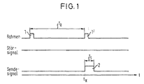
- the method according to the invention is based on the specification of a time grid (frame), which is defined in FIG. 1 by frame pulses 1, 1 ', which are arranged one after the other at time intervals T R and thereby form frame intervals T R.
- frame which is defined in FIG. 1 by frame pulses 1, 1 ', which are arranged one after the other at time intervals T R and thereby form frame intervals T R.
- the received signal is observed and examined for the reception of interference signals within the frame interval T R in order to determine the optimum time for emitting the next light signal depending on an interference signal that occurs. If no interference signal occurs by the end of the frame interval T R , the next light signal is transmitted at its standard transmission time t N , as shown in FIG. 1.
- the light signal is represented by a rectangular transmission pulse 2 with the width T S (transmission interval T S ).
- the light signal can also be formed, for example, by a sequence of light pulses or by an arbitrarily shaped signal.
- the evaluation of the received signal to determine an optimal transmission time is interrupted and the received signal is used for the detection of objects present in the monitoring area.
- a signal value received during the transmission interval T S indicates the presence or absence of an object in the monitoring area.
- the system switches back to receiving and evaluating an interference signal in order to determine the optimal transmission time of the next transmission pulse as a function of an interference signal occurring in the next frame interval T R.
- the evaluation of the received signal it is also possible to allow the evaluation of the received signal to determine the optimum transmission time to continue in parallel during the transmission interval T S , so that in this way the determination of the optimal transmission time for the next light signal begins earlier. This is particularly useful if the current light signal is emitted at the end of the frame and the transmission interval T S extends into the beginning of the next frame.
- a waiting time T C shown in broken lines in FIG. 2 is triggered with the start of the interference signal 3 at time t 0 . If a signal edge occurs again during the waiting time T C , as is the case in FIG. 2 at the time t i , the waiting time T C is ended prematurely and started again.
- the transmission pulse 2 Since no further interference signal occurs within this second waiting time T C in the case shown in FIG. 2, after the second waiting time T C has elapsed, the transmission pulse 2 is transmitted in time before its standard transmission time t N at time t S. If the duration T l of the interference signal 3 is longer than the waiting time T C , the transmission pulse 2 is emitted during the high interference level. It is therefore advantageous not to evaluate the level of the received signal directly, but rather to evaluate the level difference of the received signal during the transmission interval T S and the received signal shortly before the beginning of the transmission interval T S as a detection signal. In this way it is prevented that an interference signal received during the transmission interval T S , which exceeds the threshold value predetermined for a detection, triggers an incorrect object detection signal.
- the triggering of the waiting times T C can be controlled by the occurrence of signal edges, but also by reaching or exceeding or falling below predetermined threshold values.
- a waiting time T C is advantageously only triggered when a positive threshold value is exceeded or a negative threshold value is undershot. This ensures, for example, that no further waiting time T C is triggered by decaying overshoot processes.
- the waiting times can be implemented, for example, by a counter, as is described in more detail in relation to FIG. 7, the length of the waiting time T C being definable by a predeterminable counter reading.
- a decision as to whether the present interference signal is a one-time interference signal or an alternating interference signal can be made, for example, by counting the number of waiting times T C triggered. For example, in the case of rectangular interference signals, as shown in FIG. 2, a maximum of three waiting times T C can be triggered, namely by the rising edge, by the falling edge and by the end of the overshoot process that follows the falling edge. If a fourth waiting time T C is triggered by the interference signal or the third waiting time T C is ended prematurely, the method according to the invention is not a one-time interference signal, but an alternating interference signal which, for example, according to the description of FIG 5 to 7 is treated. In this way, the number of waiting times T C occurring or the premature termination of a waiting time T C can be used as a clear distinguishing feature between one-time interference signals and alternating interference signals.
- the transmission pulse 2 is normally transmitted at its standard transmission time t N at the end of the frame interval T R in the interference-free case.
- t N the transmission time at the end of the frame interval T R in the interference-free case.
- the end of the frame represents a critical point in time in terms of interference detection and suppression.
- the transmitted transmission pulses are adjacent arranged light button with the respective frame ends and thus with the transmission times in the trouble-free Case of one working according to the method according to the invention
- Light button together and these emitted external transmission pulses from that according to the inventive method receiving light sensor as interference signals so can these interference signals are not used to determine the optimal transmission times of the light signals are used.
- this is prevented by the fact that the transmission pulse 2 ′′ is already transmitted at a time t S , which is preferred by a time interval T V compared to the standard transmission time t N of the transmission pulse 2 ′′ is when an interference signal has not been detected in the current frame interval T R up to the time t S nor in one of the three previous frame intervals.
- interference signals received in parallel with the frame ends such as can be generated by an adjacent light scanner, are generated , after the transmission pulse 2 ′′ has been transmitted in the transmission interval T S , so that the optimum transmission time for the next light signal can be determined on the basis of these interference pulses, as was described for FIG. 2.
- FIG. 4 shows a special case of the method described in FIG. 2 for the treatment of unique interference signals according to the invention.
- a waiting time T C is triggered by the end of the interference pulse 3. Since the end of the waiting time T C would be after the end of the frame interval T R in the example according to FIG. 4, the frame interval is extended in this case by the remaining interval T ' R , so that the end of the waiting time T C with the end of the Total frame interval T R + T ' R coincides.
- the transmission pulse 2 is then transmitted, as in the case according to FIG. 2.
- the subsequent to the extended frame interval T R + T 'R frame interval T R again has the original length.
- the received signal is first observed at the beginning of the frame interval T R and classified according to its type. This can, for example, as described for FIG. 2 described, characterized happen that are triggered on reaching or exceeding and falling below predetermined threshold values waiting times T C, and upon initiation of more than three waiting times T C and at a premature termination of the third waiting time T C the received interference signal is classified as an alternating interference signal, for example as a sinusoidal interference signal according to FIG. 5.
- alternating interference signal for example as a sinusoidal interference signal according to FIG. 5.
- the received signals are cleaned up before the evaluation of DC signal components.
- the next negative half-wave 5 of the interference signal is determined and the next transmission pulse 2 is emitted during the duration of the negative half-wave 5.
- the transmission pulse 2 is thus transmitted at a time t S , which is earlier than the standard transmission time t N.
- the interference signal contains no negative half-waves, then the interference signal only through the positive half-waves classified as an alternating interference signal and after classification the transmit pulse 2 in the next between two positive half-wave interference-free interval.
- the transmission pulse 2 inside the negative half-wave or within the interference-free Intermediate interval ensures that under none Possibly an error detection of one in the surveillance area existing object occurs, as in the following to Fig. 6 is explained in more detail.
- FIG. 6 shows in the upper half the received signal 6, which is composed of the sinusoidal interference signal 4 according to FIG. 5 and the transmission pulse 2 reflected, for example, on an object present in the monitoring area.
- the transmission pulse 2 was emitted during the reception of the negative half-wave of the sinusoidal interference signal 4 by a time interval T D after the start of the negative half-wave, so that both the beginning and the end of the transmission interval T S during reception of the negative half-wave of the sinusoidal interference signal 4 come to rest.
- the detection signal 7 which is only evaluated during the transmission time interval T S for the detection of an object in the monitoring area, has a lower level than the corresponding detection signal in the fault-free case over its entire duration. This means that the difference dU this level is negative. If the level of the detection signal 7 is above a predetermined threshold value at the end of the signal interval T S , this is assessed as the detection of an object present in the monitoring area. Since in all cases only a reduction in the detection level is possible by superimposing the received transmission signal with the negative half-wave of the interference signal, an erroneous detection of an object can thus be excluded.
- Fig. 7 shows a typical waveform generated by a real RF lamp in a light receiver.
- this interference signal 8 has positive and negative half-waves 9, 9 ', 10, 10' of different lengths. Since the duration of the shorter negative half-wave is usually shorter than the duration of the transmission interval T S , it must be ensured that the transmission pulse 2 is transmitted during the reception of the longer negative half-wave 10 '.
- the longest negative half-wave is first determined, and then the transmission pulse is emitted during the next longest negative half-wave. If, for example at time t 2 in FIG. 7, the second negative half-wave 10 'has been recognized as a longer negative half-wave, it is necessary to wait until the next-but-one negative half-wave 10''' before sending out the transmission pulse 2.
- a Counting process started in ascending direction. With the beginning the first negative half-wave 10, the counter is reset and started a counting process again, the one with the end the first negative half wave 10 is stopped. By the Stopping the second counting process is the interference signal classified as an alternating interference signal. The meter reading reached represents one for the duration of the first negative half wave 10 representative value.
- the counter is, for example, in Downward direction started until the counter reading at the beginning of the next positive half-wave 9 "is stopped again the final counter reading at this point is positive the second negative half wave 10 'as a longer negative half wave recognized and the transmission pulse 2 during the next but one negative half wave 10 "'emitted.
- the Transmit pulse 2 emitted during the next negative half-wave.
- the interference signal has more than two different lengths negative half waves, so the lengths of the negative Half-waves, for example, by saving the most Counter readings reached at the end of the negative half-waves and after recognizing a complete period by comparison of the stored counter readings the longest negative Half wave can be determined.
- the transmit pulse is then during the next period of the interference signal during the duration of the longest negative half-wave determined.
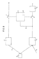
- the block diagram shown in Fig. 8 of an invention trained light button shows a light transmitter 11, which emits a transmission pulse 2, which at one in the monitoring area existing object 12 is reflected.
- the reflected transmission pulse is accompanied by an interference signal 8 received by a light receiver 13, the output via a line 19 with an interference signal evaluation unit 14 and via a first switch 15 with an object signal evaluation unit 16 is connected.
- the light transmitter 11 is connected to a voltage source U via a second switch 17, the switches 15 and 17 being actuated synchronously by the interference signal evaluation unit 14.
- the switches 15, 17 are closed, so that the light transmitter 11 emits a transmission pulse 2 due to the voltage U applied via the switch 15, which pulse is received by the light receiver 13 and supplied to the object signal evaluation unit 16 via the switch 17 .
- the switches 15, 17 are opened again by the interference signal evaluation unit 14, so that the received interference signals 8 cannot influence the object signal evaluation unit 16.
- the received interference signals 8 are fed via line 19 to the interference signal evaluation unit 14 and are evaluated by the latter to determine the optimal transmission time of the next transmission pulse 2.
- the interference signal evaluation unit 14 comprises a counter 18, which is suitable both for determining the lengths of the negative half-waves of interference signals and for realizing the waiting times T C , as described for FIGS. 2 to 7.
Landscapes
- Physics & Mathematics (AREA)
- Life Sciences & Earth Sciences (AREA)
- General Life Sciences & Earth Sciences (AREA)
- General Physics & Mathematics (AREA)
- Geophysics (AREA)
- Optical Communication System (AREA)
- Burglar Alarm Systems (AREA)
- Geophysics And Detection Of Objects (AREA)
- Photometry And Measurement Of Optical Pulse Characteristics (AREA)
Description
- Fig. 1
- ein Signal-Zeit-Diagramm zur Verdeutlichung des erfindungsgemäßen Verfahrens bei Abwesenheit eines Störsignals,
- Fig. 2
- ein Signal-Zeit-Diagramm bei Auftreten eines einmaligen Störsignals,
- Fig. 3
- ein Signal-Zeit-Diagramm nach einer weiteren Ausführungsform des erfindungsgemäßen Verfahrens bei Abwesenheit eines Störsignals,
- Fig. 4
- ein Signal-Zeit-Diagramm nach einer weiteren Ausführungsform des erfindungsgemäßen Verfahrens bei Auftreten eines einmaligen Störsignals,
- Fig. 5
- ein Signal-Zeit-Diagramm bei Auftreten eines sinusförmigen Störsignals,
- Fig. 6
- ein die Auswertung der empfangenen Signale verdeutlichender Ausschnitt eines Signal-Zeit-Diagramms,
- Fig. 7
- einen typischen Verlauf des Eingangssignals eines Lichtempfängers beim Lichtempfang von HF-Lampen und
- Fig. 8
- ein Blockschaltbild eines erfindungsgemäß ausgebildeten Lichttasters.
Claims (13)
- Verfahren zum Betrieb eines optischen Lichttasters zur Feststellung von in einem Überwachungsbereich vorhandenen Gegenständen, bei dem in bestimmten zeitlichen Abständen Lichtsignale (2, 2', 2") in den Überwachungsbereich ausgesandt, die ausgesandten Lichtsignale (2, 2', 2") sowie auftretende Störsignale (3, 4, 8) empfangen und zur Feststellung der im Überwachungsbereich vorhandenen Gegenstände ausgewertet werden,
dadurch gekennzeichnet, daß das Aussenden und Empfangen der Lichtsignale (2, 2', 2") sowie das Empfangen der Störsignale (3, 4, 8) jeweils in zeitlich aufeinanderfolgenden Rahmenintervallen (TR) erfolgt, bei Abwesenheit eines Störsignals (3, 4, 8) innerhalb eines Rahmenintervalls (TR) das Aussenden des Lichtsignals (2, 2', 2") am einen Norm-Sendezeitpunkt (tN) des jeweiligen Lichtsignals (2, 2', 2") definierenden Ende des Rahmenintervalls (TR) erfolgt, und bei Auftreten eines Störsignals (3, 4, 8) innerhalb eines Rahmenintervalls (TR) das Aussenden des nächsten Lichtsignals (2, 2', 2") gegenüber seinem Norm-Sendezeitpunkt (tN) zeitlich vorgezogen wird. - Verfahren nach Anspruch 1,
dadurch gekennzeichnet, daß die Rahmenintervalle (TR) im wesentlichen gleich lang sind, und/oder daß das innerhalb eines Rahmenintervalls (TR) auftretende Störsignal als Wechsel-Störsignal (4, 8) oder als einmaliges Störsignal (3) klassifiziert wird und daß abhängig von der jeweiligen Klassifizierung bzw. von der Abwesenheit eines Störsignals (3, 4, 8) im Rahmenintervall (TR) der Zeitpunkt für das Aussenden des Lichtsignals (2, 2', 2") bestimmt wird. - Verfahren nach einem der vorhergehenden Ansprüche,
dadurch gekennzeichnet, daß bei einer ansteigenden und/oder abfallenden Flanke eines innerhalb eines Rahmenintervalls (TR) auftretenden Störsignals (3, 4, 8) eine Wartezeit (TC) ausgelöst und/oder vorzeitig beendet wird, und/oder daß jeweils eine Wartezeit (TC) ausgelöst und/oder vorzeitig beendet wird, wenn ein innerhalb eines Rahmenintervalls (TR) auftretendes Störsignal (3, 4, 8) einen positiven und/oder negativen Schwellenwert unter- und/oder überschreitet bzw. erreicht, und/oder daß jeweils eine Wartezeit (TC) ausgelöst und/oder vorzeitig beendet wird, wenn ein innerhalb eines Rahmenintervalls (TR) auftretendes Störsignal (3, 4, 8) einen positiven Schwellenwert überoder einen negativen Schwellenwert unterschreitet, und/oder daß jeweils eine Wartezeit (TC) ausgelöst und/oder vorzeitig beendet wird, wenn innerhalb eines Rahmenintervalls bereits zwei Wartezeiten (TC) ausgelöst wurden und vor Ablauf der zweiten Wartezeit (TC) das Störsignal einen positiven Schwellenwert unter- oder einen negativen Schwellenwert überschreitet. - Verfahren nach Anspruch 3,
dadurch gekennzeichnet, daß durch kurz hintereinander auftretendes Unter- oder Überschreiten bzw. Erreichen der Schwellenwerte nur eine Wartezeit (TC) ausgelöst wird, und/oder daß die Schwellenwerte symmetrisch zum Nullpunkt gewählt werden, und/oder daß ein innerhalb eines Rahmenintervalls (TR) auftretendes Störsignal als einmaliges Störsignal (3) klassifiziert wird, wenn innerhalb des Rahmenintervalls (TR) die erste, die zweite oder die dritte Wartezeit (TC) abläuft, und/oder daß ein innerhalb eines Rahmenintervalls (TR) auftretendes Störsignal als Wechsel-Störsignal (4, 8) klassifiziert wird, wenn eine innerhalb des Rahmenintervalls (TR) ausgelöste dritte Wartezeit (TC) vorzeitig beendet wird. - Verfahren nach einem der vorhergehenden Ansprüche,
dadurch gekennzeichnet, daß bei einem innerhalb eines Rahmenintervalls (TR) auftretenden Wechsel-Störsignal (4, 8), insbesondere einem periodischen Störsignal, mit zumindest einer positiven (9, 9') und einer negativen (5, 10, 10', 10'', 10"') Halbwelle das Lichtsignal (2, 2', 2'') während des Empfangs der negativen Halbwelle (5, 10''') ausgesandt wird, und/oder daß bei einem innerhalb eines Rahmenintervalls (TR) auftretenden periodischen Störsignal (4, 8) mit mehreren unterschiedlich langen positiven (9, 9') und negativen (10, 10', 10'', 10''') Halbwellen das Lichtsignal (2, 2', 2'') während des Empfangs der längsten negativen Halbwelle (10''') ausgesandt wird. - Verfahren nach Anspruch 5,
dadurch gekennzeichnet, daß der Beginn der ersten innerhalb eines Rahmenintervalls (TR) auftretenden negativen Halbwelle (10) eines periodischen Störsignals (8) ausgehend von einem bestimmten Anfangswert, insbesondere von Null, einen Zählvorgang auslöst, daß der am Ende der negativen Halbwelle (10) erreichte, für die Dauer dieser Halbwelle (10) repräsentative Zählerstand mit dem Beginn der darauffolgenden positiven Halbwelle (9') gehalten wird, daß der Beginn der nächsten negativen Halbwelle (10') ausgehend von dem gehaltenen Zählerstand einen dem ersten Zählvorgang entgegengesetzt gerichteten Zählvorgang auslöst, und daß der mit Beginn der nächsten positiven Halbwelle (9'') erreichte End-Zählerstand zur Bestimmung der längeren negativen Halbwelle (10', 10''') ausgewertet wird, und/oder daß nach der Bestimmung der längeren negativen Halbwelle (10', 10"') das Lichtsignal (2, 2', 2'') während des Auftretens der nächsten längeren negativen Halbwelle (10"') ausgesandt wird, und/oder daß der erste Zählvorgang ein Aufwärtszählen und der zweite Zählvorgang ein Abwärtszähien ist und das Lichtsignal (2, 2', 2'') während des Auftretens der nächsten negativen Halbwelle (10") ausgesandt wird, wenn der End-Zählerstand größer als der Anfangswert, insbesondere positiv ist, und das Lichtsignal (2, 2', 2'') während des Empfangs der übernächsten negativen Halbwelle (10''') ausgesandt wird, wenn der End-Zählerstand kleiner als der Anfangswert, insbesondere negativ ist, und/oder daß der Beginn der ersten innerhalb eines Rahmenintervalls (TR) auftretenden positiven Halbwelle (9) einen Zählvorgang auslöst und daß der Zählerstand am Ende der positiven Halbwelle (9) auf den Anfangswert zurückgesetzt wird, wenn der Beginn der ersten positiven Halbwelle (9) vor dem Beginn der ersten innerhalb des Rahmenintervalls (TR) auftretenden negativen Halbwelle (10) liegt. - Verfahren nach einem der Ansprüche 5 oder 6,
dadurch gekennzeichnet, daß die Dauer des Lichtsignals (2, 2', 2") und der Beginn des Aussendens des Lichtsignals (2, 2', 2'') so gewählt werden, daß das Aussenden des Lichtsignals (2, 2', 2'') noch vor dem Ende der negativen Halbwelle (5, 10''') beendet wird, und/oder daß der Beginn eines innerhalb eines Rahmenintervalls (TR) einmalig auftretenden Störsignals (3) eine erste Wartezeit (TC) auslöst und das Lichtsignal (2, 2', 2'') nach Ablauf der ersten Wartezeit (TC) ausgesandt wird, wenn die erste Wartezeit (TC) kürzer als die Dauer des Störsignals (3) ist, und/oder daß das Ende eines innerhalb eines Rahmenintervalls (TR) einmalig auftretenden Störsignals (3) eine zweite Wartezeit (TC) auslöst und das Lichtsignal (2, 2', 2") nach Ablauf der zweiten Wartezeit (TC) ausgesandt wird, wenn innerhalb der zweiten Wartezeit (TC) kein weiteres Störsignal (3, 4, 8) empfangen wird. - Verfahren nach einem der Ansprüche 3 bis 7,
dadurch gekennzeichnet, daß die Wartezeiten (TC) durch Zählvorgänge und der Ablauf der Wartezeiten (TC) durch Erreichen eines vorbestimmten Zählerstandes oder durch einen Zählerüberlauf realisiert werden, und/oder daß die Wartezeiten (TC) gleich lang sind, und/oder daß das Rahmenintervall (TR) verlängert wird, wenn das Ende der Wartezeit (TC) zeitlich hinter dem Ende eines Normallänge aufweisenden Rahmenintervalls (TR) liegt, wobei insbesondere das Rahmenintervall (TR) bis zum Ablauf der Wartezeit (TC) verlängert wird. - Verfahren nach einem der Ansprüche 4 bis 8,
dadurch gekennzeichnet, daß das Rahmenintervall (TR) verlängert wird, wenn die negative Halbwelle, während der das nächste Lichtsignal (2, 2', 2'') ausgesandt werden soll, zeitlich hinter dem Ende eines Normallänge aufweisenden Rahmenintervalls (TR) liegt, wobei insbesondere das Rahmenintervall (TR) bis zum Aussenden des Lichtsignals verlängert wird. - Verfahren nach einem der vorhergehenden Ansprüche,
dadurch gekennzeichnet, daß das empfangene Signal (6) von Gleichsignalanteilen bereinigt wird, und/oder daß das Aussenden des nächsten Lichtsignals (2") gegenüber seinem Norm-Sendezeitpunkt (tN) um ein bestimmtes Zeitintervall (TV) vorgezogen wird, wenn bis zum Beginn dieses Zeitintervalls (TV) weder innerhalb des aktuellen Rahmenintervalls (TR) noch innerhalb einer bestimmten Anzahl der vorhergehenden Rahmenintervalle (TR) ein Störsignal (3, 4, 8) empfangen wurde, wobei insbesondere die Dauer des Zeitintervalls (TV) fest vorbestimmt ist oder zufällig bestimmt wird, und/oder daß die Anzahl der vorhergehenden störungsfreien Rahmenintervalle (TR) gleich drei ist. - Verfahren nach einem der vorhergehenden Ansprüche,
dadurch gekennzeichnet, daß als Empfangssignal (6) zur Feststellung eines im Überwachungsbereich vorhandenen Gegenstandes die Pegeldifferenz zwischen dem während des Aussendens des Lichtsignals (2, 2', 2'') empfangenen Signal und dem kurz vor Aussenden des Lichtsignals (2, 2', 2'') empfangenen Signal ausgewertet wird, und/oder daß die Störsignalauswertung während des Aussendens des Lichtsignals (2, 2', 2'') unterbrochen wird, und/oder daß die Störsignalauswertung bis zum Abklingen der durch das ausgesandte Lichtsignal (2, 2', 2'') hervorgerufenen Überschwingvorgänge unterbrochen wird. - Optischer Lichttaster zur Feststellung von in einem Überwachungsbereich vorhandenen Gegenständen (12) ausgebildet zur Durchführung des Verfahrens nach einem der vorhergehenden Ansprüche mit einem Lichtsender (11) zum Aussenden von Lichtsignalen (2) in bestimmten zeitlichen Abständen, einem Lichtempfänger (13) zum Empfangen der ausgesandten Lichtsignale (2) sowie auftretender Störsignale (8), einer Gegenstandssignal-Auswerteeinheit (16) zur Auswertung der Empfangssignale (2, 8) während der Dauer des Aussendens eines Lichtsignals (2) und zur Erzeugung eines Gegenstand-Feststellungssignals, falls sich ein Gegenstand (12) im Überwachungsbereich befindet, einer Störsignal-Auswerteeinheit (14) zur Auswertung der empfangenen Störsignale (8) im Zeitintervall zwischen zwei aufeinanderfolgend ausgesandten Lichtsignalen (2) und zur Ansteuerung des Lichtsenders (11),
dadurch gekennzeichnet, daß die Störsignal-Auswerteeinheit (14) einen Zähler (18) zur Bestimmung der Längen der negativen Halbwellen eines Wechsel-Störsignals (8) und/oder zur Erzeugung eines Steuersignals für die Aussendung eines Lichtsignals (2) durch den Lichtsender (11) bei Erreichen eines bestimmten Zählerstandes nach Auftreten eines einmaligen Störsignals (3) umfaßt. - Lichttaster nach Anspruch 12,
dadurch gekennzeichnet, daß die Störsignal-Auswerteeinheit (14) eine Auslösestufe umfaßt, die bei Auftreten eines Wechsel-Störsignals (8) die Aussendung des Lichtsignals (2) während der negativen Halbwelle des Wechsel-Störsignals (8). bewirkt, und/oder daß die Auslösestufe die Aussendung des Lichtsignals (2) während der längsten negativen Halbwelle des Wechsel-Störsignals (8) bewirkt, und/oder daß der Lichtempfänger (13) nur während der Dauer des Aussendes eines Lichtsignals (2) mit der Gegenstandssignal-Auswerteeinheit (16) über eine Umschaltvorrichtung (15) verbunden ist.
Applications Claiming Priority (2)
| Application Number | Priority Date | Filing Date | Title |
|---|---|---|---|
| DE19537615A DE19537615B4 (de) | 1995-10-09 | 1995-10-09 | Verfahren zum Betrieb eines optischen Lichttasters |
| DE19537615 | 1995-10-09 |
Publications (3)
| Publication Number | Publication Date |
|---|---|
| EP0768545A2 EP0768545A2 (de) | 1997-04-16 |
| EP0768545A3 EP0768545A3 (de) | 1999-09-15 |
| EP0768545B1 true EP0768545B1 (de) | 2002-06-12 |
Family
ID=7774423
Family Applications (1)
| Application Number | Title | Priority Date | Filing Date |
|---|---|---|---|
| EP96113873A Expired - Lifetime EP0768545B1 (de) | 1995-10-09 | 1996-08-29 | Verfahren zum Betrieb eines optischen Lichttasters |
Country Status (5)
| Country | Link |
|---|---|
| US (1) | US5852292A (de) |
| EP (1) | EP0768545B1 (de) |
| JP (1) | JPH09133580A (de) |
| DE (2) | DE19537615B4 (de) |
| DK (1) | DK0768545T3 (de) |
Cited By (1)
| Publication number | Priority date | Publication date | Assignee | Title |
|---|---|---|---|---|
| DE10136242C5 (de) * | 2000-08-16 | 2016-11-17 | Schneider Electric Industries Sas | Photozellendetektor |
Families Citing this family (11)
| Publication number | Priority date | Publication date | Assignee | Title |
|---|---|---|---|---|
| US6411215B1 (en) | 1999-02-19 | 2002-06-25 | J. Mitchell Shnier | Optical methods for detecting the position or state of an object |
| DE19926214A1 (de) * | 1999-06-09 | 2001-01-11 | Balluff Gebhard Gmbh & Co | Verfahren zur Unterdrückung von Störsignalen in Optosensoren/Näherungsschaltern und Schaltungsanordnung zur Druchführung dieses Verfahrens |
| DE10011598B4 (de) * | 2000-03-10 | 2010-07-22 | Sick Ag | Optoelektronische Sensoranordnung sowie Verfahren zum Betreiben einer optoelektronischen Sensoranordnung |
| CA2409638A1 (en) * | 2001-10-29 | 2003-04-29 | Sunx Limited | Photoelectric sensor |
| US7042600B2 (en) * | 2002-01-07 | 2006-05-09 | Xerox Corporation | Method and apparatus for eliminating lamp strobing in a digital input scanner |
| JPWO2005045473A1 (ja) * | 2003-11-10 | 2007-05-17 | オムロン株式会社 | 処理装置および対象物検出装置 |
| DE102006023971B8 (de) * | 2006-05-22 | 2009-04-30 | Pepperl + Fuchs Gmbh | Optischer Sensor und Verfahren zum Nachweis von Personen, Tieren oder Gegenständen |
| DE102008005064B4 (de) | 2008-01-18 | 2010-06-17 | Sick Ag | Optoelektronisches Detektionsverfahren und optoelektronischer Detektor |
| JP6590553B2 (ja) * | 2015-06-29 | 2019-10-16 | アズビル株式会社 | 光電センサ |
| EP3739365B1 (de) * | 2019-05-13 | 2024-04-24 | Leuze electronic GmbH + Co. KG | Optischer sensor |
| DE102019125321A1 (de) * | 2019-09-20 | 2021-03-25 | Sick Ag | Optoelektronische sensoranordnung und sensorsystem |
Family Cites Families (12)
| Publication number | Priority date | Publication date | Assignee | Title |
|---|---|---|---|---|
| JP2558459B2 (ja) * | 1987-04-15 | 1996-11-27 | アルプス電気株式会社 | 光電検出回路 |
| KR900000230B1 (ko) * | 1987-07-14 | 1990-01-23 | 삼성전자 주식회사 | 주파수 검출기를 이용한 광전스위치 |
| DE3823007A1 (de) * | 1988-07-07 | 1990-01-11 | Telefunken Electronic Gmbh | Optischer sensor |
| JP3015059B2 (ja) * | 1989-12-20 | 2000-02-28 | 株式会社トプコン | 光検出方法およびそのための装置 |
| EP0456482B1 (de) * | 1990-05-11 | 1997-04-09 | Idec Izumi Corporation | Photoelektrischer Schaltkreis |
| DE4031142C3 (de) * | 1990-10-02 | 1998-01-29 | Sick Optik Elektronik Erwin | Optischer Lichttaster und Verfahren zu seinem Betrieb |
| DE4141469C2 (de) * | 1991-12-16 | 1997-07-17 | Sick Ag | Verfahren zum Betrieb einer optischen Sensoranordnung zur Feststellung von in einem Überwachungsbereich vorhandenen Gegenständen sowie eine solche optische Sensoranordnung |
| DE4141468C2 (de) * | 1991-12-16 | 1994-06-30 | Sick Optik Elektronik Erwin | Optische Sensoranordnung und Verfahren zu deren Betrieb |
| DE4237311C1 (de) * | 1992-08-25 | 1993-12-16 | Leuze Electronic Gmbh & Co | Aus einem Sender und einem Empfänger bestehende Einrichtung zum Erfassen von Gegenständen |
| DE4319451C1 (de) * | 1992-11-05 | 1994-08-25 | Leuze Electronic Gmbh & Co | Aus einem Sender und einem Empfänger bestehende Einrichtung zum Erfassen von Gegenständen |
| DE4324590C2 (de) * | 1993-07-22 | 1995-06-08 | Leuze Electronic Gmbh & Co | Lichtschrankenanordnung mit geregelter Ansprechempfindlichkeit |
| US5550369A (en) * | 1994-02-28 | 1996-08-27 | Electro-Pro, Inc. | Triangulation position detection method and apparatus |
-
1995
- 1995-10-09 DE DE19537615A patent/DE19537615B4/de not_active Expired - Fee Related
-
1996
- 1996-08-29 EP EP96113873A patent/EP0768545B1/de not_active Expired - Lifetime
- 1996-08-29 DE DE59609323T patent/DE59609323D1/de not_active Expired - Lifetime
- 1996-08-29 DK DK96113873T patent/DK0768545T3/da active
- 1996-10-08 US US08/727,061 patent/US5852292A/en not_active Expired - Lifetime
- 1996-10-09 JP JP26876596A patent/JPH09133580A/ja active Pending
Cited By (1)
| Publication number | Priority date | Publication date | Assignee | Title |
|---|---|---|---|---|
| DE10136242C5 (de) * | 2000-08-16 | 2016-11-17 | Schneider Electric Industries Sas | Photozellendetektor |
Also Published As
| Publication number | Publication date |
|---|---|
| EP0768545A2 (de) | 1997-04-16 |
| US5852292A (en) | 1998-12-22 |
| EP0768545A3 (de) | 1999-09-15 |
| JPH09133580A (ja) | 1997-05-20 |
| DE19537615A1 (de) | 1997-04-10 |
| DE59609323D1 (de) | 2002-07-18 |
| DK0768545T3 (da) | 2002-10-07 |
| DE19537615B4 (de) | 2005-02-17 |
Similar Documents
| Publication | Publication Date | Title |
|---|---|---|
| DE19611195C1 (de) | Verfahren zum Betrieb einer Lichtschrankenanordnung | |
| DE19537615B4 (de) | Verfahren zum Betrieb eines optischen Lichttasters | |
| DE1262331B (de) | Verfahren und Schaltungsanordnung zur Datenuebertragung | |
| DE4212440A1 (de) | Verfahren zum feststellen von uebertragungsfehlern bei einem katastrophenverhuetungsueberwachungssystem | |
| DE10211387B4 (de) | Strahlungsimpulse verwendender Sensor | |
| DE10355008A1 (de) | Verfahren zur Verarbeitung eines Empfangssignals und optischer Sensor | |
| EP2159601B1 (de) | Verfahren zum Festlegen einer Empfangsschwelle, Vorrichtung zum Festlegen einer Empfangsschwelle, Ultraschallsonar | |
| DE4319451C1 (de) | Aus einem Sender und einem Empfänger bestehende Einrichtung zum Erfassen von Gegenständen | |
| DE19926214A1 (de) | Verfahren zur Unterdrückung von Störsignalen in Optosensoren/Näherungsschaltern und Schaltungsanordnung zur Druchführung dieses Verfahrens | |
| EP2983009B1 (de) | Betreiben eines optoelektronischen sensors mittels eines verfahrens zum aussenden von lichtimpulsen | |
| DE2529589C2 (de) | Elektronisches Sicherheitssystem mit einer Signaldetektorschaltung | |
| DE4427885A1 (de) | Verfahren zur Verbesserung des Störabstandes in einem Übertragungssystem durch die Bildung von Flächenäquivalenten | |
| EP2278360B1 (de) | Verfahren zum Betrieb eines optischen Sensors | |
| DE19833353C2 (de) | Lichttaster | |
| EP1391752B1 (de) | Lichtgitter | |
| DE10136242C5 (de) | Photozellendetektor | |
| DE10200905B4 (de) | Photoelektrischer Schalter | |
| DE19930458C2 (de) | Tonruf-Frequenzbestimmungsvorrichtung und -verfahren | |
| DE19521511C1 (de) | Verfahren zur Ultraschallüberwachung, insbesondere von Innenräumen von Kraftfahrzeugen | |
| DE4237311C1 (de) | Aus einem Sender und einem Empfänger bestehende Einrichtung zum Erfassen von Gegenständen | |
| EP0772788B1 (de) | Verfahren und vorrichtung zur elimination von störsignalen bei einer lichtschranke | |
| DE19932692A1 (de) | Verfahren zur Abtastung biphase codierter digitaler Signale | |
| EP1843175B1 (de) | Synchronisationsverfahren für eine Lichtschranke und entsprechenden Lichtschranke | |
| EP0584510B1 (de) | Aus einem Sender und einem Empfänger bestehende Einrichtung zum Erfassen von Gegenständen | |
| DE4135158A1 (de) | Verfahren zum erfassen und korrigieren von impulsrauschen in einem multifunktions-fernsteuerungssender |
Legal Events
| Date | Code | Title | Description |
|---|---|---|---|
| PUAI | Public reference made under article 153(3) epc to a published international application that has entered the european phase |
Free format text: ORIGINAL CODE: 0009012 |
|
| AK | Designated contracting states |
Kind code of ref document: A2 Designated state(s): CH DE DK FR GB IT LI |
|
| PUAL | Search report despatched |
Free format text: ORIGINAL CODE: 0009013 |
|
| RIC1 | Information provided on ipc code assigned before grant |
Free format text: 6G 01V 8/10 A, 6G 01S 7/483 B |
|
| AK | Designated contracting states |
Kind code of ref document: A3 Designated state(s): CH DE DK FR GB IT LI |
|
| 17P | Request for examination filed |
Effective date: 19991019 |
|
| 17Q | First examination report despatched |
Effective date: 20010111 |
|
| GRAG | Despatch of communication of intention to grant |
Free format text: ORIGINAL CODE: EPIDOS AGRA |
|
| GRAG | Despatch of communication of intention to grant |
Free format text: ORIGINAL CODE: EPIDOS AGRA |
|
| GRAH | Despatch of communication of intention to grant a patent |
Free format text: ORIGINAL CODE: EPIDOS IGRA |
|
| GRAH | Despatch of communication of intention to grant a patent |
Free format text: ORIGINAL CODE: EPIDOS IGRA |
|
| GRAA | (expected) grant |
Free format text: ORIGINAL CODE: 0009210 |
|
| AK | Designated contracting states |
Kind code of ref document: B1 Designated state(s): CH DE DK FR GB IT LI |
|
| REG | Reference to a national code |
Ref country code: GB Ref legal event code: FG4D Free format text: NOT ENGLISH |
|
| REG | Reference to a national code |
Ref country code: CH Ref legal event code: EP |
|
| REF | Corresponds to: |
Ref document number: 59609323 Country of ref document: DE Date of ref document: 20020718 |
|
| GBT | Gb: translation of ep patent filed (gb section 77(6)(a)/1977) |
Effective date: 20020721 |
|
| ET | Fr: translation filed | ||
| PG25 | Lapsed in a contracting state [announced via postgrant information from national office to epo] |
Ref country code: DK Free format text: LAPSE BECAUSE OF NON-PAYMENT OF DUE FEES Effective date: 20020930 |
|
| REG | Reference to a national code |
Ref country code: DK Ref legal event code: T3 |
|
| PLBQ | Unpublished change to opponent data |
Free format text: ORIGINAL CODE: EPIDOS OPPO |
|
| PLBI | Opposition filed |
Free format text: ORIGINAL CODE: 0009260 |
|
| PLBF | Reply of patent proprietor to notice(s) of opposition |
Free format text: ORIGINAL CODE: EPIDOS OBSO |
|
| REG | Reference to a national code |
Ref country code: DK Ref legal event code: EBP |
|
| 26 | Opposition filed |
Opponent name: LEUZE ELECTRONIC GMBH + CO Effective date: 20030303 |
|
| PGFP | Annual fee paid to national office [announced via postgrant information from national office to epo] |
Ref country code: GB Payment date: 20030730 Year of fee payment: 8 |
|
| PLBB | Reply of patent proprietor to notice(s) of opposition received |
Free format text: ORIGINAL CODE: EPIDOSNOBS3 |
|
| PLCK | Communication despatched that opposition was rejected |
Free format text: ORIGINAL CODE: EPIDOSNREJ1 |
|
| PGFP | Annual fee paid to national office [announced via postgrant information from national office to epo] |
Ref country code: FR Payment date: 20040820 Year of fee payment: 9 |
|
| PG25 | Lapsed in a contracting state [announced via postgrant information from national office to epo] |
Ref country code: GB Free format text: LAPSE BECAUSE OF NON-PAYMENT OF DUE FEES Effective date: 20040829 |
|
| PLBN | Opposition rejected |
Free format text: ORIGINAL CODE: 0009273 |
|
| STAA | Information on the status of an ep patent application or granted ep patent |
Free format text: STATUS: OPPOSITION REJECTED |
|
| 27O | Opposition rejected |
Effective date: 20040720 |
|
| GBPC | Gb: european patent ceased through non-payment of renewal fee |
Effective date: 20040829 |
|
| PGFP | Annual fee paid to national office [announced via postgrant information from national office to epo] |
Ref country code: CH Payment date: 20050824 Year of fee payment: 10 |
|
| PG25 | Lapsed in a contracting state [announced via postgrant information from national office to epo] |
Ref country code: FR Free format text: LAPSE BECAUSE OF NON-PAYMENT OF DUE FEES Effective date: 20060428 |
|
| REG | Reference to a national code |
Ref country code: FR Ref legal event code: ST Effective date: 20060428 |
|
| PG25 | Lapsed in a contracting state [announced via postgrant information from national office to epo] |
Ref country code: LI Free format text: LAPSE BECAUSE OF NON-PAYMENT OF DUE FEES Effective date: 20060831 Ref country code: CH Free format text: LAPSE BECAUSE OF NON-PAYMENT OF DUE FEES Effective date: 20060831 |
|
| REG | Reference to a national code |
Ref country code: CH Ref legal event code: PL |
|
| PGFP | Annual fee paid to national office [announced via postgrant information from national office to epo] |
Ref country code: IT Payment date: 20100826 Year of fee payment: 15 |
|
| PGFP | Annual fee paid to national office [announced via postgrant information from national office to epo] |
Ref country code: DE Payment date: 20100922 Year of fee payment: 15 |
|
| PG25 | Lapsed in a contracting state [announced via postgrant information from national office to epo] |
Ref country code: IT Free format text: LAPSE BECAUSE OF NON-PAYMENT OF DUE FEES Effective date: 20110829 |
|
| PG25 | Lapsed in a contracting state [announced via postgrant information from national office to epo] |
Ref country code: DE Free format text: LAPSE BECAUSE OF NON-PAYMENT OF DUE FEES Effective date: 20130301 |
|
| REG | Reference to a national code |
Ref country code: DE Ref legal event code: R119 Ref document number: 59609323 Country of ref document: DE Effective date: 20130301 |