EP0768128B1 - Appareillage de rivetage opérant par chocs et procédé de mise en oeuvre de cet appareillage - Google Patents
Appareillage de rivetage opérant par chocs et procédé de mise en oeuvre de cet appareillage Download PDFInfo
- Publication number
- EP0768128B1 EP0768128B1 EP96402152A EP96402152A EP0768128B1 EP 0768128 B1 EP0768128 B1 EP 0768128B1 EP 96402152 A EP96402152 A EP 96402152A EP 96402152 A EP96402152 A EP 96402152A EP 0768128 B1 EP0768128 B1 EP 0768128B1
- Authority
- EP
- European Patent Office
- Prior art keywords
- riveting
- rivet
- workpieces
- hole
- driving means
- Prior art date
- Legal status (The legal status is an assumption and is not a legal conclusion. Google has not performed a legal analysis and makes no representation as to the accuracy of the status listed.)
- Expired - Lifetime
Links
- 238000000034 method Methods 0.000 title claims description 8
- 239000012636 effector Substances 0.000 claims description 6
- 230000001360 synchronised effect Effects 0.000 claims description 5
- 230000000712 assembly Effects 0.000 claims description 4
- 238000000429 assembly Methods 0.000 claims description 4
- 238000004364 calculation method Methods 0.000 claims description 2
- 230000006870 function Effects 0.000 claims description 2
- 238000003032 molecular docking Methods 0.000 description 7
- 230000035939 shock Effects 0.000 description 6
- 238000006073 displacement reaction Methods 0.000 description 5
- 238000009527 percussion Methods 0.000 description 4
- 239000000463 material Substances 0.000 description 2
- 230000001133 acceleration Effects 0.000 description 1
- 239000003990 capacitor Substances 0.000 description 1
- 230000015556 catabolic process Effects 0.000 description 1
- 230000008878 coupling Effects 0.000 description 1
- 238000010168 coupling process Methods 0.000 description 1
- 238000005859 coupling reaction Methods 0.000 description 1
- 238000006731 degradation reaction Methods 0.000 description 1
- 239000002360 explosive Substances 0.000 description 1
- 239000002184 metal Substances 0.000 description 1
- 210000000056 organ Anatomy 0.000 description 1
- 230000010355 oscillation Effects 0.000 description 1
- 230000000284 resting effect Effects 0.000 description 1
- 238000007493 shaping process Methods 0.000 description 1
- 230000001960 triggered effect Effects 0.000 description 1
Images

Classifications
-
- B—PERFORMING OPERATIONS; TRANSPORTING
- B21—MECHANICAL METAL-WORKING WITHOUT ESSENTIALLY REMOVING MATERIAL; PUNCHING METAL
- B21J—FORGING; HAMMERING; PRESSING METAL; RIVETING; FORGE FURNACES
- B21J15/00—Riveting
- B21J15/10—Riveting machines
- B21J15/14—Riveting machines specially adapted for riveting specific articles, e.g. brake lining machines
- B21J15/142—Aerospace structures
-
- B—PERFORMING OPERATIONS; TRANSPORTING
- B21—MECHANICAL METAL-WORKING WITHOUT ESSENTIALLY REMOVING MATERIAL; PUNCHING METAL
- B21J—FORGING; HAMMERING; PRESSING METAL; RIVETING; FORGE FURNACES
- B21J15/00—Riveting
- B21J15/10—Riveting machines
-
- B—PERFORMING OPERATIONS; TRANSPORTING
- B21—MECHANICAL METAL-WORKING WITHOUT ESSENTIALLY REMOVING MATERIAL; PUNCHING METAL
- B21J—FORGING; HAMMERING; PRESSING METAL; RIVETING; FORGE FURNACES
- B21J15/00—Riveting
- B21J15/10—Riveting machines
- B21J15/16—Drives for riveting machines; Transmission means therefor
- B21J15/24—Drives for riveting machines; Transmission means therefor operated by electro-magnets
-
- B—PERFORMING OPERATIONS; TRANSPORTING
- B21—MECHANICAL METAL-WORKING WITHOUT ESSENTIALLY REMOVING MATERIAL; PUNCHING METAL
- B21J—FORGING; HAMMERING; PRESSING METAL; RIVETING; FORGE FURNACES
- B21J15/00—Riveting
- B21J15/10—Riveting machines
- B21J15/16—Drives for riveting machines; Transmission means therefor
- B21J15/26—Drives for riveting machines; Transmission means therefor operated by rotary drive, e.g. by electric motor
-
- Y—GENERAL TAGGING OF NEW TECHNOLOGICAL DEVELOPMENTS; GENERAL TAGGING OF CROSS-SECTIONAL TECHNOLOGIES SPANNING OVER SEVERAL SECTIONS OF THE IPC; TECHNICAL SUBJECTS COVERED BY FORMER USPC CROSS-REFERENCE ART COLLECTIONS [XRACs] AND DIGESTS
- Y10—TECHNICAL SUBJECTS COVERED BY FORMER USPC
- Y10T—TECHNICAL SUBJECTS COVERED BY FORMER US CLASSIFICATION
- Y10T29/00—Metal working
- Y10T29/49—Method of mechanical manufacture
- Y10T29/49764—Method of mechanical manufacture with testing or indicating
-
- Y—GENERAL TAGGING OF NEW TECHNOLOGICAL DEVELOPMENTS; GENERAL TAGGING OF CROSS-SECTIONAL TECHNOLOGIES SPANNING OVER SEVERAL SECTIONS OF THE IPC; TECHNICAL SUBJECTS COVERED BY FORMER USPC CROSS-REFERENCE ART COLLECTIONS [XRACs] AND DIGESTS
- Y10—TECHNICAL SUBJECTS COVERED BY FORMER USPC
- Y10T—TECHNICAL SUBJECTS COVERED BY FORMER US CLASSIFICATION
- Y10T29/00—Metal working
- Y10T29/49—Method of mechanical manufacture
- Y10T29/49826—Assembling or joining
- Y10T29/49947—Assembling or joining by applying separate fastener
- Y10T29/49954—Fastener deformed after application
- Y10T29/49956—Riveting
-
- Y—GENERAL TAGGING OF NEW TECHNOLOGICAL DEVELOPMENTS; GENERAL TAGGING OF CROSS-SECTIONAL TECHNOLOGIES SPANNING OVER SEVERAL SECTIONS OF THE IPC; TECHNICAL SUBJECTS COVERED BY FORMER USPC CROSS-REFERENCE ART COLLECTIONS [XRACs] AND DIGESTS
- Y10—TECHNICAL SUBJECTS COVERED BY FORMER USPC
- Y10T—TECHNICAL SUBJECTS COVERED BY FORMER US CLASSIFICATION
- Y10T29/00—Metal working
- Y10T29/53—Means to assemble or disassemble
- Y10T29/53039—Means to assemble or disassemble with control means energized in response to activator stimulated by condition sensor
- Y10T29/53061—Responsive to work or work-related machine element
Definitions
- the present invention relates to an apparatus for riveting and a method of implementing this equipment.
- a rivet is a connecting member intended to connect together two or more pieces each drilled with a hole.
- the rivet includes a rod which is intended to be threaded in the parts holes, after these holes have been brought in axial coincidence.
- the rod must be threaded in the holes in such a way that part of the rod makes projection from each end of the passage formed by the juxtaposed holes.
- the rod is deformable, and / or is associated to a deformable ring, which is part of the rivet.
- the deformation of the rivet can be obtained using forces acting slowly, or by single or repeated shocks.
- an "anvil” that is to say a piece that we can consider as fixed and undeformable
- we place one end of the rivet resting on the anvil and we exercise the shock (s) using a “snap” which acts on the opposite end of the rivet rod.
- This way of to do is not entirely satisfactory in terms of theoretical, because the deformation of the part of the rivet which is close to the anvil causes a slight displacement, or deformation, parts.
- the need to have a fixed or large anvil is a constraint annoying.
- the rivet to be shaped is initially made up of a symmetrical cylindrical part, homogeneous, placed symmetrically with respect to the parts to be riveting, it is clear that the result, as far as displacements and constraints imposed on these parts, will the better the difference between the kinetic energies of the two percussion tools, and the time interval that will separate their impact on one end of the rivet, will be more low. It will not be exactly the same in case the rivet to be shaped is not symmetrical, and presents a head for example. Many other factors can intervene: for example, if we consider that a shock is the very rapid application of a force to an object, the mode of variation of this force is not unimportant.
- the object of the present invention is to provide a riveting apparatus which, operating according to the principle of "synchronous percussion" is simpler, less bulky, easier to use and less expensive than those of the prior art.
- the invention provides a riveting apparatus of the type comprising two tools capable of acting in a substantially synchronous manner on the opposite ends of a rivet, this apparatus comprising two bearing members, on each of which is mounted a latch assembly, movable along a defined path, means for holding the load-bearing organs in a position such that when an active face of the dowel comes into contact with a corresponding end of the rivet, this active face moves substantially parallel to the axis of the rivet, each carrier member being provided with training means capable of communicating to the corresponding bolt moving along its trajectory towards the other sufficient energy for shaping the rivet, control means being provided for actuating the means almost simultaneously of drive, this apparatus having for particularity that the drive means each include a motor electric capable of printing a speed such that when the dowel meets the rivet, the snap assembly has kinetic energy sufficient to form the rivet, and the control means are capable of operating the two drive means of such that the snaps meet the rivet at format with a time difference and a difference kinetic energy lower than limits chosen for avoid moving or moving parts
- set with snap means here a set of elements joined together and comprising a snap, which is a piece intended to come and exercise impact on the rivet, this part preferably being in one material capable of withstanding a large number of impacts without deformation or degradation, a mass, the inertia of which is calculated according to the desired result, and possibly connecting means for connecting the head and the earth training means.
- Electric motor must have starting torque very important if you relate to its weight and space, in order to best communicate energy desired kinetics.
- the brushless electric motors are the ones that meet the better under these conditions.
- each chisel by relation to the support member is rectilinear.
- This arrangement is known in the prior art. Note that other trajectories are possible. For example, for reduce friction, we can predict that the assembly snap is mounted on a swivel arm.
- the drive means include at least one ball screw comprising a shaft and a cage, one of these components being driven by the engine and the other being arranged to drive the entire latch according to its trajectory.
- This modality is particularly advantageous if the trajectory of the chisel is straight because the connection of the cage to the whole snap can be very simple. It should be noted on this subject that is preferable in all cases than the connection between the snap assembly and the training means include shock absorbing means for protecting these drive means, and the engine itself, shock corresponding to the impact of the snap on the rivet.
- At least one carrier member is an effector mounted on a robotic arm, and the supporting members are provided with means for clamping the parts to be riveted against each other before riveting, without imposing constraints or displacements on them unacceptable.
- the means for clamping the parts are constituted by tubular members inside which the snap can circulate.
- Such means are also described in document EP-A-0.402.222.
- this process comprises, after step c) and before step e), an additional step consisting of bring the rivet into a position fixed in advance by compared to the parts to be connected by riveting.
- This additional step prevents a part of the kinetic energy of one of the sets to be used to move the rivet before impact on the other buttonhole.
- position fixed in advance we mean a position average fixed in advance in case it is necessary to take into account the tolerances concerning the length of the rivet.
- the drive motor of a dowel operating at slow speed.
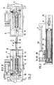
- Figure 3 is a partial section on a plane perpendicular to that of Figure 2.
- the equipment described is shown in the position where he is about to form a rivet 1 driven in in a hole which crosses two pieces of sheet metal 2 and 3, which must be bonded together by riveting.
- the apparatus comprises two sets 4 and 5, which are identical, and act in opposite directions. Each set is mounted on a separate robotic arm A, B, these arms being placed in front of opposite sides of parts 2 and 3 to be bound. Set 4 will be described below, on the left in the figures 1 and 2, it being understood that the assembly 5 comprises the same elements.
- Set 4 includes a rear plate 6, which carries means 7 for coupling to the robotic arm A corresponding.
- Set 4 also includes a plate front 8, fixedly connected to the rear plate 6 by rigid uprights 9.
- the plate 8 carries a docking nose 10, which is mounted on the front plate 8 so that it can move along an axis 11, which in the position active, is substantially coincident with the axis of the rivet 1.
- the docking nose 10 is movable relative to the plate 8, and is provided with means not shown which exert on the nose docking 10 a force tending to spread said nose docking plate in the direction of room 2, so to hold and tighten parts 2, 3 together, cooperation with the nose 10 of the effector 5.
- the assembly 5 is arranged in such a way that its axis 11 is also confused with the axis of the rivet, and that its nose docking 10 exerts on part 3 a force equal to that that the nose of the assembly of the assembly 4 exerts on the part 2, which keeps these two pieces tight against one another the other, provided, of course, that the robotic arms which carry the two plates 6 are immobilized.
- the chassis constituted by the plates 6, 8 and the uprights 9 carries a guide tube 12, the axis 11 of which coincides with that of the docking nose. Inside this guide tube can slide a riveting mass 13, which carries, rigidly, at its end facing the docking nose 10, a snap 14, of smaller diameter. Ground 13 slides in the guide tube 12 with gentle friction.
- the tube 12 has a longitudinal lumen 15 see Figure 3, through which passes a connecting piece 16 which is integral with mass 13 and comes into engagement with a training plate 17.
- This training plate is integral with two cages 18, which are each part of a ball screw device.
- the trees 19 of these two ball screw devices have their axes parallel to the axis 11, and are immobilized axially with respect to the chassis formed by the plates 6 and 8 and the uprights 9, by fixed supports 20.
- the shafts 19 of the ball screws are driven in rotation by a brushless electric motor 21, by via a conventional belt drive 22 notched and pulleys. We could also predict that at least one of the shafts 19 is driven directly by a motor electric. It is understood that the rotation of the motor 21 is transformed, by means of ball screws 18, 19, into a rectilinear movement of the lug assembly 13 and 14, so as to move the latter towards the rivet with controlled speed, and / or acceleration.
- a control assembly connected to both arms robotics A and B.
- This set is capable of handling data relating to the various parameters of the operation, previously stored or transmitted by sensors mounted on the effectors, and to emit signals from control of the two motors 21 at times selected in based on these parameters.
Landscapes
- Engineering & Computer Science (AREA)
- Mechanical Engineering (AREA)
- Insertion Pins And Rivets (AREA)
- Automatic Assembly (AREA)
Description
- Figure 1 est une vue schématique d'ensemble, en élévation d'un appareillage selon l'invention.
- Figure 2 est une vue en élévation et coupe partielle de l'appareillage, à plus grande échelle.
Claims (9)
- Appareillage pour relier des pièces par rivetage du type comportant deux outils capables d'agir de façon sensiblement synchrone sur les extrémités opposées d'un rivet, cet appareillage comprenant deux organes porteurs, sur chacun desquels est monté un ensemble à bouterolle (13, 14, 15), mobile selon une trajectoire définie grâce à des moyens de guidage (12), des moyens pour maintenir les organes porteurs dans une position telle que, lorsqu'une face active de la bouterolle (13) arrive en contact avec une extrémité correspondante du rivet, cette face active se déplace sensiblement parallèlement à l'axe du rivet (1), chaque organe porteur étant pourvu de moyens d'entraínement aptes à communiquer à la bouterolle correspondante se déplaçant le long de sa trajectoire en direction de l'autre bouterolle une énergie suffisante pour la mise en forme du rivet, des moyens de commande (25) étant prévus pour actionner à peu près simultanément les moyens d'entraínement,
caractérisé en ce que les moyens d'entraínement comprennent chacun un moteur électrique (21) apte à imprimer à l'ensemble à bouterolle une vitesse telle que, lorsque la bouterolle rencontre le rivet, l'ensemble à bouterolle a une énergie cinétique suffisante pour former le rivet,
et en ce que les moyens de commande (25) sont capables d'actionner les deux moteurs électriques (21), de telle façon que les bouterolles rencontrent le rivet à mettre en forme avec un décalage de temps et une différence d'énergie cinétique inférieurs à des limites choisies pour éviter aux pièces à relier des déplacements ou des contraintes exagérées. - Appareillage selon la revendication 1, caractérisé en ce que le moteur électrique (21) est un moteur sans balais.
- Appareillage selon la revendication 1 ou 2, caractérisé en ce que les moyens d'entraínement comprennent au moins un dispositif à vis à bille (18, 19) comprenant un arbre (19) et une cage (18), l'un de ces composants étant entraíné en rotation par le moteur et l'autre étant disposé pour entraíner l'ensemble à bouterolle selon sa trajectoire.
- Appareillage selon l'une des revendications 1 à 3, caractérisé en ce qu'au moins un organe porteur est un effecteur (4, 5) monté sur un bras robotique (A, B), et les organes porteurs sont pourvus de moyens (10) pour serrer les pièces à riveter l'une contre l'autre avant le rivetage, sans leur imposer de contraintes ou déplacements inacceptables.
- Appareillage selon la revendication 4, caractérisé en ce que les moyens pour serrer les pièces sont constitués par des organes tubulaires (10) à l'intérieur desquels la bouterolle peut circuler.
- Appareillage de rivetage selon l'une des revendications précédentes, caractérisé en ce que chacun des moyens de guidage (12), ensembles à bouterolle (13 à 15) et moyens d'entraínement (16 à 22), est conçu pour être monté sur un effecteur (A, B) sur lequel sont également montés (10) des moyens pour maintenir et serrer ensemble deux pièces (2, 3) à relier par rivetage, des moyens pour préparer un trou dans ces pièces et des moyens pour amener un rivet dans le trou, ces moyens pouvant être amenés successivement sensiblement dans l'axe du trou.
- Appareillage selon la revendication 6, caractérisé en ce que l'effecteur porte également des moyens pour déterminer la forme exacte du trou, les indications fournies par ces moyens étant utilisées par les moyens de commande pour définir les déplacements des deux ensembles à bouterolle.
- Procédé pour la mise en oeuvre d'un appareillage selon l'une des revendications 1 à 7, caractérisé en ce qu'il comprend les étapes suivantes :a) mettre en mémoire des paramètres relatifs à un trou préparé dans deux pièces (2, 3) à solidariser par rivetage et à un rivet (1) destiné à être introduit dans le trou en vue du rivetage, ainsi que des paramètres relatifs à l'ensemble à bouterolle et aux moyens d'entraínement,b) amener chacune des bouterolles (14) dans une position de départ à peu près fixe par rapport aux pièces à solidariser et au rivet,c) déterminer avec précision les positions relatives des bouterolles, du rivet et des pièces à relier par rivetage,d) calculer, en fonction desdits paramètres mis en mémoire et desdites données de position, au moins un paramètre choisi parmi le décalage de temps entre le démarrage de chacun des ensembles à bouterolle et la distance de chacune des bouterolles au rivet au moment du démarrage,e) actionner chacun des moyens d'entraínement en fonction du résultat des calculs de l'étape d).
- Procédé selon la revendication 8, caractérisé en ce qu'il comprend, après l'étape c) et avant l'étape e), une étape supplémentaire consistant à amener le rivet dans une position fixée à l'avance par rapport aux pièces à relier par rivetage.
Applications Claiming Priority (2)
| Application Number | Priority Date | Filing Date | Title |
|---|---|---|---|
| FR9511935 | 1995-10-11 | ||
| FR9511935A FR2739794B1 (fr) | 1995-10-11 | 1995-10-11 | Appareillage de rivetage operant par chocs et procede de mise en oeuvre de cet appareillage |
Publications (2)
| Publication Number | Publication Date |
|---|---|
| EP0768128A1 EP0768128A1 (fr) | 1997-04-16 |
| EP0768128B1 true EP0768128B1 (fr) | 1999-12-15 |
Family
ID=9483431
Family Applications (1)
| Application Number | Title | Priority Date | Filing Date |
|---|---|---|---|
| EP96402152A Expired - Lifetime EP0768128B1 (fr) | 1995-10-11 | 1996-10-10 | Appareillage de rivetage opérant par chocs et procédé de mise en oeuvre de cet appareillage |
Country Status (6)
| Country | Link |
|---|---|
| US (1) | US6014802A (fr) |
| EP (1) | EP0768128B1 (fr) |
| JP (1) | JPH09108767A (fr) |
| CA (1) | CA2187420A1 (fr) |
| DE (1) | DE69605635T2 (fr) |
| FR (1) | FR2739794B1 (fr) |
Cited By (2)
| Publication number | Priority date | Publication date | Assignee | Title |
|---|---|---|---|---|
| DE19731222B4 (de) * | 1997-07-21 | 2009-10-08 | Newfrey Llc, Newark | Verfahren zum Ausbilden einer Stanznietverbindung sowie eine Fügevorrichtung für Stanzniete |
| US8146240B2 (en) | 1997-07-21 | 2012-04-03 | Newfrey Llc | Riveting system and process for forming a riveted joint |
Families Citing this family (27)
| Publication number | Priority date | Publication date | Assignee | Title |
|---|---|---|---|---|
| DE19729368A1 (de) * | 1997-07-09 | 1999-01-14 | Ortwin Hahn | Vorrichtung und Verfahren zum mechanischen Fügen von Blechen, Profilen und/oder Mehrblechverbindungen |
| US9015920B2 (en) | 1997-07-21 | 2015-04-28 | Newfrey Llc | Riveting system and process for forming a riveted joint |
| US6789309B2 (en) * | 2000-02-22 | 2004-09-14 | Newfrey Llc | Self-piercing robotic rivet setting system |
| US7340048B2 (en) * | 2000-07-14 | 2008-03-04 | Context Connect Llc | System and method for directory services and e-commerce across multi-provider networks |
| US6731927B1 (en) | 2000-07-14 | 2004-05-04 | Context Connect, Inc. | System and method for context association |
| US7899173B2 (en) * | 2000-07-14 | 2011-03-01 | Context Connect, Llc | Communication connectivity via context association, advertising sponsorship, and multiple contact databases |
| US6910263B2 (en) * | 2001-12-25 | 2005-06-28 | Newfrey Llc | Self-piercing rivet setting apparatus and system |
| CA2471676A1 (fr) * | 2001-12-27 | 2003-07-31 | Newfrey Llc. | Dispositif de rivetage par poinconnage automatique, et matrice utilisee a cet effet |
| DE10330253A1 (de) * | 2003-07-04 | 2005-01-20 | Robert Bosch Gmbh | Sensorelement |
| DE102004005859A1 (de) * | 2004-02-05 | 2005-08-25 | Claas Fertigungstechnik Gmbh | Vorrichtung zur Fixierung von Nietelementen in Bauteilen |
| FR2865952B1 (fr) * | 2004-02-10 | 2006-06-23 | Airbus France | Procede et dispositif d'usinage mecanique de panneaux flexibles en particulier de forme complexe |
| DE112005002827B4 (de) * | 2004-11-19 | 2014-02-20 | Richard Bergner Verbindungstechnik Gmbh & Co. Kg | Roboterhand sowie Verfahren zum automatischen Setzen eines Elements |
| US8301302B2 (en) * | 2008-05-08 | 2012-10-30 | The Boeing Company | Synchronous robotic operation on a structure having a confined space |
| US20100217437A1 (en) * | 2009-02-24 | 2010-08-26 | Branko Sarh | Autonomous robotic assembly system |
| US8666546B2 (en) * | 2009-07-10 | 2014-03-04 | The Boeing Company | Autonomous robotic platform |
| JP5854811B2 (ja) * | 2011-12-19 | 2016-02-09 | Dmg森精機株式会社 | 工作機械 |
| WO2013103210A1 (fr) * | 2012-01-06 | 2013-07-11 | Lee Chun-Woo | Manipulateur et robot doté de celui-ci |
| US9027220B2 (en) | 2012-08-07 | 2015-05-12 | Newfrey Llc | Rivet setting machine |
| KR20140102633A (ko) * | 2014-05-20 | 2014-08-22 | 절강 리닉스 모터 컴퍼니 리미티드 | 브러시 홀더와 브러시 홀더 플레이트 리벳 체결 장치 |
| DE102014007553B4 (de) * | 2014-05-22 | 2019-08-22 | Daimler Ag | Verfahren zum Verbinden von wenigstens zwei Bauteilen sowie Vorrichtung zum Durchführen eines solchen Verfahrens |
| US9937549B2 (en) | 2014-07-09 | 2018-04-10 | The Boeing Company | Two-stage riveting |
| US9446444B2 (en) | 2014-08-21 | 2016-09-20 | The Boeing Company | Apparatus and method for synchronized multi-stage electromagnetic rivet guns |
| US20160138299A1 (en) * | 2014-10-20 | 2016-05-19 | John Powers, III | Multiple driver head post driving system |
| ES2632166B1 (es) * | 2016-02-08 | 2018-05-08 | Manuel Torres Martinez | Dispositivo de mecanizado de superficies laminares curvas |
| US10596691B2 (en) * | 2017-01-30 | 2020-03-24 | Stuart Topp | Devices and methods of using them to assemble two or more workpieces to each other |
| CN112958741B (zh) * | 2021-03-16 | 2022-09-02 | 西安爱生技术集团公司 | 一种无头铆钉手持式电磁铆接装置及方法 |
| CN117816900B (zh) * | 2023-12-26 | 2026-06-09 | 哈尔滨飞机工业集团有限责任公司 | 一种人机协作进行实心铆钉铆接的系统和方法 |
Family Cites Families (14)
| Publication number | Priority date | Publication date | Assignee | Title |
|---|---|---|---|---|
| US1483919A (en) * | 1922-03-31 | 1924-02-19 | Charles J Walker | Electric riveter |
| CA1234482A (fr) * | 1984-12-19 | 1988-03-29 | Daifuku Co., Ltd. | Methode et dispositif de montage de pieces d'automobiles sur les deux faces d'une carrosserie |
| US4720897A (en) * | 1985-08-30 | 1988-01-26 | Gemcor Engineering Corp. | Automatic fastening machine with brushless electric motor for drill spindle drive |
| DE3535761C1 (de) * | 1985-10-07 | 1987-03-26 | Messerschmitt Boelkow Blohm | Nietautomat |
| DE3715927A1 (de) * | 1987-05-13 | 1988-12-01 | Messerschmitt Boelkow Blohm | Vorrichtung und verfahren zum automatisch gesteuerten bohrsenken und vernieten mit hilfe eines wenigstens zweiteiligen verbindungselementes |
| US4967947A (en) * | 1988-03-23 | 1990-11-06 | Branko Sarh | Multi-function riveting/fastening machine and method of operating |
| US4885836A (en) * | 1988-04-19 | 1989-12-12 | Imta | Riveting process and apparatus |
| US4955119A (en) * | 1989-07-11 | 1990-09-11 | Imta | Multi-task end effector for robotic machining center |
| US4999896A (en) * | 1989-10-25 | 1991-03-19 | Gemcor Engineering Corporation | Automatic double-flush riveting |
| US4995148A (en) * | 1990-03-30 | 1991-02-26 | Imta | Robotically controlled multi-task end effector |
| US5231747A (en) * | 1990-12-21 | 1993-08-03 | The Boeing Company | Drill/rivet device |
| DE4126602A1 (de) * | 1991-08-12 | 1993-02-18 | Gesipa Blindniettechnik | Blindnietgeraet |
| US5136873A (en) * | 1991-11-13 | 1992-08-11 | S.A.R.G. Research Assoc, Ltd. | Automatic blind rivet setting device |
| US5634746A (en) * | 1992-09-21 | 1997-06-03 | The Boeing Co. | Normality control for a tool nose |
-
1995
- 1995-10-11 FR FR9511935A patent/FR2739794B1/fr not_active Expired - Fee Related
-
1996
- 1996-10-08 CA CA002187420A patent/CA2187420A1/fr not_active Abandoned
- 1996-10-09 US US08/728,059 patent/US6014802A/en not_active Expired - Fee Related
- 1996-10-10 EP EP96402152A patent/EP0768128B1/fr not_active Expired - Lifetime
- 1996-10-10 DE DE69605635T patent/DE69605635T2/de not_active Expired - Fee Related
- 1996-10-11 JP JP8270122A patent/JPH09108767A/ja not_active Abandoned
Cited By (3)
| Publication number | Priority date | Publication date | Assignee | Title |
|---|---|---|---|---|
| DE19731222B4 (de) * | 1997-07-21 | 2009-10-08 | Newfrey Llc, Newark | Verfahren zum Ausbilden einer Stanznietverbindung sowie eine Fügevorrichtung für Stanzniete |
| US8146240B2 (en) | 1997-07-21 | 2012-04-03 | Newfrey Llc | Riveting system and process for forming a riveted joint |
| DE19731222C5 (de) * | 1997-07-21 | 2016-10-13 | Newfrey Llc | Verfahren zum Ausbilden einer Stanznietverbindung sowie eine Fügevorrichtung für Stanzniete |
Also Published As
| Publication number | Publication date |
|---|---|
| DE69605635T2 (de) | 2000-06-21 |
| FR2739794B1 (fr) | 1997-12-26 |
| DE69605635D1 (de) | 2000-01-20 |
| US6014802A (en) | 2000-01-18 |
| JPH09108767A (ja) | 1997-04-28 |
| FR2739794A1 (fr) | 1997-04-18 |
| EP0768128A1 (fr) | 1997-04-16 |
| CA2187420A1 (fr) | 1997-04-12 |
Similar Documents
| Publication | Publication Date | Title |
|---|---|---|
| EP0768128A1 (fr) | Appareillage de rivetage opérant par chocs et procédé de mise en oeuvre de cet appareillage | |
| FR2607050A1 (fr) | Outil a moteur a deux vitesses dont le passage d'une vitesse a l'autre est effectue automatiquement par un dispositif a came, tel que perceuses ou analogues | |
| CH636794A5 (fr) | Perforatrice a percussion. | |
| EP1034895A1 (fr) | Procédé de pose d'un collier élastique et outillages le mettant en oeuvre | |
| BE898154A (fr) | Manipuleur pour positionner des pièces à usiner ou d'autres charges. | |
| EP2872299A1 (fr) | Dispositif de transmission de mouvement a reducteur epicycloidal, reducteur epicycloidal et bras de manipulation | |
| EP1370388B1 (fr) | Dispositif d'entrainement et outil de serrage equipe d'un tel dispositif | |
| FR3015332A1 (fr) | Procede de pilotage d'un dispositif de vissage a impulsions, dispositif de pilotage et dispositif de vissage correspondants | |
| FR2494165A1 (fr) | Dispositif pour saisir et manipuler des pieces d'oeuvre | |
| EP0424190A1 (fr) | Outillage comportant une pince à deux bras articulés, avec système de détalonnage | |
| FR3105052A1 (fr) | Clé à choc à mécanisme d’impact | |
| CA1187163A (fr) | Dispositif mixte d'emission d'ondes longitudinales ou transversales | |
| EP4185500B1 (fr) | Boîtier de transmission et engin automoteur roulant équipé d'un boîtier de transmission | |
| FR2992421A3 (fr) | Module d'essai d'une pedale, notamment d'une pedale d'embrayage | |
| FR2512512A1 (fr) | Limiteur de couple pour engrenage de reduction a planetaires | |
| EP0278185A1 (fr) | Machine de soudage par résistance à commande numérique et système vis et écrou ou analogue; son mode de fonctionnement | |
| EP0071498B1 (fr) | Dispositif de transmission à variateur de vitesse incorporé | |
| FR2574334A1 (fr) | Systeme de manipulation de pieces de montage | |
| WO2018041966A1 (fr) | Dispositif de transmission mécanique et système comprenant un tel dispositif | |
| EP1110664A1 (fr) | Poste d'une ligne d'assemblage de blocs-cylindres de moteur thermique | |
| FR2633536A1 (fr) | Dispositif de marquage adaptable sur appareil de scellement | |
| EP1395379B1 (fr) | Outil portatif destine a etre utilise pour l'installation d'elements de fixation | |
| EP0318353A1 (fr) | Ensemble de rectification des manetons de vilebrequin | |
| FR2707912A1 (fr) | Dispositif de préhension fixé au nez d'un robot pour saisir des pièces plates ou peu galbées de véhicule automobile. | |
| KR102533060B1 (ko) | 리벳 공급장치 |
Legal Events
| Date | Code | Title | Description |
|---|---|---|---|
| PUAI | Public reference made under article 153(3) epc to a published international application that has entered the european phase |
Free format text: ORIGINAL CODE: 0009012 |
|
| AK | Designated contracting states |
Kind code of ref document: A1 Designated state(s): DE GB IT NL SE |
|
| 17P | Request for examination filed |
Effective date: 19970424 |
|
| GRAG | Despatch of communication of intention to grant |
Free format text: ORIGINAL CODE: EPIDOS AGRA |
|
| 17Q | First examination report despatched |
Effective date: 19981207 |
|
| GRAG | Despatch of communication of intention to grant |
Free format text: ORIGINAL CODE: EPIDOS AGRA |
|
| GRAG | Despatch of communication of intention to grant |
Free format text: ORIGINAL CODE: EPIDOS AGRA |
|
| GRAH | Despatch of communication of intention to grant a patent |
Free format text: ORIGINAL CODE: EPIDOS IGRA |
|
| GRAH | Despatch of communication of intention to grant a patent |
Free format text: ORIGINAL CODE: EPIDOS IGRA |
|
| GRAA | (expected) grant |
Free format text: ORIGINAL CODE: 0009210 |
|
| AK | Designated contracting states |
Kind code of ref document: B1 Designated state(s): DE GB IT NL SE |
|
| PG25 | Lapsed in a contracting state [announced via postgrant information from national office to epo] |
Ref country code: NL Free format text: LAPSE BECAUSE OF FAILURE TO SUBMIT A TRANSLATION OF THE DESCRIPTION OR TO PAY THE FEE WITHIN THE PRESCRIBED TIME-LIMIT Effective date: 19991215 |
|
| REF | Corresponds to: |
Ref document number: 69605635 Country of ref document: DE Date of ref document: 20000120 |
|
| GBT | Gb: translation of ep patent filed (gb section 77(6)(a)/1977) |
Effective date: 20000121 |
|
| ITF | It: translation for a ep patent filed | ||
| NLV1 | Nl: lapsed or annulled due to failure to fulfill the requirements of art. 29p and 29m of the patents act | ||
| PLBE | No opposition filed within time limit |
Free format text: ORIGINAL CODE: 0009261 |
|
| STAA | Information on the status of an ep patent application or granted ep patent |
Free format text: STATUS: NO OPPOSITION FILED WITHIN TIME LIMIT |
|
| 26N | No opposition filed | ||
| REG | Reference to a national code |
Ref country code: GB Ref legal event code: IF02 |
|
| PGFP | Annual fee paid to national office [announced via postgrant information from national office to epo] |
Ref country code: SE Payment date: 20040920 Year of fee payment: 9 |
|
| PGFP | Annual fee paid to national office [announced via postgrant information from national office to epo] |
Ref country code: GB Payment date: 20040928 Year of fee payment: 9 |
|
| PGFP | Annual fee paid to national office [announced via postgrant information from national office to epo] |
Ref country code: DE Payment date: 20041127 Year of fee payment: 9 |
|
| PG25 | Lapsed in a contracting state [announced via postgrant information from national office to epo] |
Ref country code: IT Free format text: LAPSE BECAUSE OF NON-PAYMENT OF DUE FEES Effective date: 20051010 Ref country code: GB Free format text: LAPSE BECAUSE OF NON-PAYMENT OF DUE FEES Effective date: 20051010 |
|
| PG25 | Lapsed in a contracting state [announced via postgrant information from national office to epo] |
Ref country code: SE Free format text: LAPSE BECAUSE OF NON-PAYMENT OF DUE FEES Effective date: 20051011 |
|
| PG25 | Lapsed in a contracting state [announced via postgrant information from national office to epo] |
Ref country code: DE Free format text: LAPSE BECAUSE OF NON-PAYMENT OF DUE FEES Effective date: 20060503 |
|
| EUG | Se: european patent has lapsed | ||
| GBPC | Gb: european patent ceased through non-payment of renewal fee |
Effective date: 20051010 |