EP0768053B1 - Low temperature display case - Google Patents
Low temperature display case Download PDFInfo
- Publication number
- EP0768053B1 EP0768053B1 EP96116179A EP96116179A EP0768053B1 EP 0768053 B1 EP0768053 B1 EP 0768053B1 EP 96116179 A EP96116179 A EP 96116179A EP 96116179 A EP96116179 A EP 96116179A EP 0768053 B1 EP0768053 B1 EP 0768053B1
- Authority
- EP
- European Patent Office
- Prior art keywords
- evaporator
- defrosting
- refrigerant
- display case
- low temperature
- Prior art date
- Legal status (The legal status is an assumption and is not a legal conclusion. Google has not performed a legal analysis and makes no representation as to the accuracy of the status listed.)
- Expired - Lifetime
Links
- 238000010257 thawing Methods 0.000 claims description 87
- 239000003507 refrigerant Substances 0.000 claims description 71
- 229910052751 metal Inorganic materials 0.000 claims description 37
- 239000002184 metal Substances 0.000 claims description 37
- 238000001816 cooling Methods 0.000 description 27
- 238000009413 insulation Methods 0.000 description 23
- XLYOFNOQVPJJNP-UHFFFAOYSA-N water Substances O XLYOFNOQVPJJNP-UHFFFAOYSA-N 0.000 description 22
- 238000005192 partition Methods 0.000 description 12
- 238000011084 recovery Methods 0.000 description 9
- 238000005338 heat storage Methods 0.000 description 7
- 229910000838 Al alloy Inorganic materials 0.000 description 5
- 238000010586 diagram Methods 0.000 description 4
- 239000012530 fluid Substances 0.000 description 4
- 235000015243 ice cream Nutrition 0.000 description 4
- 239000007788 liquid Substances 0.000 description 4
- 238000005086 pumping Methods 0.000 description 4
- 229910052782 aluminium Inorganic materials 0.000 description 2
- XAGFODPZIPBFFR-UHFFFAOYSA-N aluminium Chemical compound [Al] XAGFODPZIPBFFR-UHFFFAOYSA-N 0.000 description 2
- 238000007599 discharging Methods 0.000 description 2
- 235000013611 frozen food Nutrition 0.000 description 2
- 230000002093 peripheral effect Effects 0.000 description 2
- 230000001681 protective effect Effects 0.000 description 2
- 239000010935 stainless steel Substances 0.000 description 2
- 229910001220 stainless steel Inorganic materials 0.000 description 2
- 229910001335 Galvanized steel Inorganic materials 0.000 description 1
- PPBRXRYQALVLMV-UHFFFAOYSA-N Styrene Chemical compound C=CC1=CC=CC=C1 PPBRXRYQALVLMV-UHFFFAOYSA-N 0.000 description 1
- 238000005219 brazing Methods 0.000 description 1
- 230000015556 catabolic process Effects 0.000 description 1
- 235000009508 confectionery Nutrition 0.000 description 1
- 238000006731 degradation reaction Methods 0.000 description 1
- 230000006866 deterioration Effects 0.000 description 1
- 239000008397 galvanized steel Substances 0.000 description 1
- 230000020169 heat generation Effects 0.000 description 1
- 239000012774 insulation material Substances 0.000 description 1
- 230000014759 maintenance of location Effects 0.000 description 1
- 238000000034 method Methods 0.000 description 1
- 230000000717 retained effect Effects 0.000 description 1
- 230000001932 seasonal effect Effects 0.000 description 1
- 238000011144 upstream manufacturing Methods 0.000 description 1
Images




Classifications
-
- A—HUMAN NECESSITIES
- A47—FURNITURE; DOMESTIC ARTICLES OR APPLIANCES; COFFEE MILLS; SPICE MILLS; SUCTION CLEANERS IN GENERAL
- A47F—SPECIAL FURNITURE, FITTINGS, OR ACCESSORIES FOR SHOPS, STOREHOUSES, BARS, RESTAURANTS OR THE LIKE; PAYING COUNTERS
- A47F3/00—Show cases or show cabinets
- A47F3/04—Show cases or show cabinets air-conditioned, refrigerated
- A47F3/0439—Cases or cabinets of the open type
- A47F3/0443—Cases or cabinets of the open type with forced air circulation
- A47F3/0447—Cases or cabinets of the open type with forced air circulation with air curtains
-
- F—MECHANICAL ENGINEERING; LIGHTING; HEATING; WEAPONS; BLASTING
- F25—REFRIGERATION OR COOLING; COMBINED HEATING AND REFRIGERATION SYSTEMS; HEAT PUMP SYSTEMS; MANUFACTURE OR STORAGE OF ICE; LIQUEFACTION SOLIDIFICATION OF GASES
- F25D—REFRIGERATORS; COLD ROOMS; ICE-BOXES; COOLING OR FREEZING APPARATUS NOT OTHERWISE PROVIDED FOR
- F25D21/00—Defrosting; Preventing frosting; Removing condensed or defrost water
-
- F—MECHANICAL ENGINEERING; LIGHTING; HEATING; WEAPONS; BLASTING
- F25—REFRIGERATION OR COOLING; COMBINED HEATING AND REFRIGERATION SYSTEMS; HEAT PUMP SYSTEMS; MANUFACTURE OR STORAGE OF ICE; LIQUEFACTION SOLIDIFICATION OF GASES
- F25B—REFRIGERATION MACHINES, PLANTS OR SYSTEMS; COMBINED HEATING AND REFRIGERATION SYSTEMS; HEAT PUMP SYSTEMS
- F25B47/00—Arrangements for preventing or removing deposits or corrosion, not provided for in another subclass
- F25B47/02—Defrosting cycles
- F25B47/022—Defrosting cycles hot gas defrosting
-
- F—MECHANICAL ENGINEERING; LIGHTING; HEATING; WEAPONS; BLASTING
- F25—REFRIGERATION OR COOLING; COMBINED HEATING AND REFRIGERATION SYSTEMS; HEAT PUMP SYSTEMS; MANUFACTURE OR STORAGE OF ICE; LIQUEFACTION SOLIDIFICATION OF GASES
- F25D—REFRIGERATORS; COLD ROOMS; ICE-BOXES; COOLING OR FREEZING APPARATUS NOT OTHERWISE PROVIDED FOR
- F25D21/00—Defrosting; Preventing frosting; Removing condensed or defrost water
- F25D21/06—Removing frost
- F25D21/08—Removing frost by electric heating
Definitions
- the present invention relates to a low temperature display case wherein are formed ducts, which communicate with the rear and the lower side of a storage chamber that is open to the front, whereby cool air, which is obtained by heat exchange in an evaporator that is provided upright in a duct at the rear, is discharged by a blower from openings at the upper edge of the storage chamber.
- a low temperature display case of the above described type is designed with a division wall located on the internal face of a substantially C-shaped heat insulation wall and a deck pan located at the bottom to define a storage chamber and a duct, and an evaporator and a blower are provided in the duct.
- air cooled in the duct is circulated through the storage chamber.
- the low temperature display case 100 is constructed with a substantially C-shaped heat insulation division wall 103 mounted, with an intervening space, inside a heat insulation wall 102, which is also substantially C shaped.
- a partition panel 104 is attached, with an intervening space, at its rear side to the upper and the lower internal side of the heat insulation division wall 103.
- Deck struts 106 are provided on each side and in the center of the partition panel 104.
- the lower ends of the deck struts 106 and of the partition panel 104 are secured either directly or via another member to a metal fitting 107, the ends of which are fixed to frames (not shown) on either side of the heat insulation wall 102.
- a deck pan 108 is provided, with an intervening space, above a bottom wall 103A of the heat insulation division wall 103.
- a storage chamber 109 which is open to the front, is defined by an area enclosed by the partition panel 104 and the deck pan 108.
- An evaporator 113 that is included in a cooler is provided upright at the rear inside the inner duct 112, with the front lower end of its tube sheet (not shown) fixed to the metal fitting 107.
- a suction blower 114 (for an inner duct) is provided below the deck pan 108 in the front internal portion of the inner duct 112, and a suction blower 116 (for an outer duct) is provided in the front internal portion of the outer duct 111, which is located below the inner duct 112.
- the top surface of the bottom wall 103A, of the heat insulation division wall 103 inclines downward at an angle of 4 degrees, for example, toward a drain hole 117, which is located beneath the blower 114.
- the top face of the bottom wall 103A therefore, serves as a drain pan 118, and drain pan heaters (electric heaters) 119 for the drain pan 118 are provided near the drain hole 117.
- the drain hole 117 communicates with the outer duct 111, and defrosting heaters (electric heaters) 122 and an attachment plate 121 are provided inside the inner duct 112 at the upper rear portion of the drain pan 118.
- the defrosting heaters 122 are located forward of the evaporator 113 and under the metal fitting 107, so that during defrosting, water falling from the evaporator 113 will not fall directly on the heaters 122.
- the upper ends of the inner and outer ducts 112 and 111 communicate respectively with an inner discharge opening 124 and an outer discharge opening 126, which are positioned near the upper edge of the opening of the storage chamber 109.
- An inner intake opening 127 and an outer intake opening 128 are formed at the lower edge of the opening of the storage chamber 109, and from the front the opening 127 is located behind the opening 128.
- the inner intake opening 127 communicates with the inner duct 112, and the outer intake opening 128 communicates with the outer duct 111.
- decks 129 on which frozen foods, such as ice cream can be displayed, are supported as a series of steps by the deck struts 106.
- the cooling device when the cooling device is activated to drive the blowers 114 and 116, air is drawn in by the blower 114 and is driven toward the evaporator 113.
- the air that passes through the evaporator 113 and is cooled by heat exchange rises along the inner duct 112 and is expelled toward the front opening of the storage chamber 109 from the inner discharge opening 124, which is formed at the upper edge of the front opening of the storage chamber 109.
- a curtain of cool air covers the front opening of the storage chamber 109 while the cool air circulates through the storage chamber 109 to maintain therein at a predetermined refrigerating temperature.
- the air that is driven by the blower 116 rises along the outer duct layer 111 and is expelled toward the front opening of the storage chamber 109 from the outer discharge opening 126, which is formed at the upper edge of the opening of the storage chamber 109. As a result, a protective air curtain is formed outside the cool air curtain.
- frost builds up on the evaporator 113 and around the periphery of its inner duct 112. Therefore, while the blowers 114 and 116 are being operated, the defrosting heaters 122 are periodically rendered conductive, and warm air from the blower 114 is conveyed to the evaporator 113 to heat it. At the same time, refrigerant gas is discharged at a high temperature from a compressor (not shown) of the cooling device and flows through the pipe in the evaporator 113 to heat it from the inside. In this manner, defrosting of the evaporator 113 is performed.
- the defrosting of the evaporator 113 is completed when the temperature of the evaporator 113 has reached a specific defrosting end temperature, e.g., +10°C.
- a specific defrosting end temperature e.g., +10°C.
- the defrosting time can be reduced, thawing of goods, such as ice cream, that are displayed in the storage chamber 109 can be prevented, and deterioration of the quality of the goods can be inhibited.
- frost will remain in those locations that are hard for the high temperature refrigerant gas and the heat from the defrosting heaters 122 to reach. For example, cold water and ice fall on that portion of the drain pan 118 that is below the evaporator 113, and since that location is relatively distant from both the drain pan heaters 119 and the defrosting heaters 122, the temperature there rises only to 0°C.
- the inclination angle of the drain pan 118 is small, e.g., four degrees, and water dose not drain away well and tends to remain at that location, hard frost builds up on the portion of the drain pan 118 that lies below the evaporator 113 and impedes the circulation of cool air along the inner duct layer 112.
- metal fitting 107 that contacts the evaporator 113 is greatly affected by the cooling provided by the evaporator 113, frost tends to build up on it, and water that falls on it from the top of the evaporator 113 tends to remain there. And as the metal fitting 107 is located apart from the pipe of the evaporator 113 and the defrosting heaters 122, when the defrosting time is reduced, as is described above, incomplete defrosting will occur at the metal fitting 107, and residual frost will build up thereon that can break the pipe in the evaporator 113.
- US-A-4 145 893 is directed to a low temperature display case comprising: a duct, a storage chamber having an opening at the front, an evaporator, a blower for discharging cooled air, a drain guide face at the bottom of said duct, defrosting heaters and a sharply sloped portion below said evaporator, wherein heat generated by that frosting heaters aids defrosting of the case.
- EP-A-0 345 098 discloses a refrigerating system in which defrosting of the evaporator is effected by feading high temperature refrigerant into the evaporator.
- Patent Abstracts of Japan, vol. 014, no. 159 (M-0956) provides a drain hole to which a drain guide face is inclined.
- a low temperature display case which comprises:
- one part of the defrosting heaters is located close to a position where incomplete defrosting tends to occur.
- a tube sheet for the evaporator is made of a metal having high thermal conductivity.
- a metal strut fitting which is fixed to front lower ends of the tube sheet of the evaporator, is made of a metal having high thermal conductivity.
- one part of the defrosting heaters is located near the metal strut fitting.
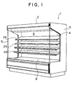
- Fig. 1 is a perspective view of a low temperature display case 1 according to the present invention
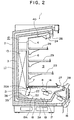
- Fig. 2 is a vertical cross sectional side view of the low temperature display case 1
- Fig. 3 is a perspective view of an evaporator 13
- Fig. 4 is a refrigerant circuit diagram for a cooling device R for cooling the low temperature display case 1.
- the low temperature display case 1 of the present invention is a refrigerating openfront display case that is installed in a store, such as a supermarket or a convenience store, to display chilled confections, such as ice cream, that are for sale.
- the low temperature display case 1 has a substantially C shaped heat insulation wall 2, and side plates 5 that are attached to both sides of the insulation wall 2.
- Heat insulation division wall 3, which is substantially C shaped, is so mounted inside the heat insulation wall 2 that there is an intervening space between them.
- a partition panel 4 is provided inside the upper portion of the heat insulation division wall 3 and extends outward, describing an intervening space.
- Deck struts 6 are provided at both ends and in the center of the partition panel 4.
- the lower ends of the deck struts 6 and of the partition panel 4 are secured either directly or via another member to a metal fitting 7, the ends of which are fixed to frames (not shown) on either side of the heat insulation wall 2.
- a deck pan 8 is provided, with an intervening space, above a bottom wall 3A of the heat insulation division wall 3.
- a storage chamber 9, which is open to the front, is defined by an area enclosed by the partition panel 4 and the deck pan 8.
- the evaporator 13 that is included in a cooling device is provided upright at the rear inside the inner duct 12.
- the evaporator 13 comprises a plurality of aluminum heat exchange fins 31, tube sheets 32, 33 and 34, which are located at the center and the sides of the heat exchange fins 31; and a sinuously shaped refrigerant pipe 36 that is passed through the tube sheets 32, 33 and 34.
- the refrigerant pipe 36 has a refrigerant inlet 36A and a refrigerant outlet 36B at its left end near the tube sheet 32.
- the center tube sheet 33 and the right end tube sheet 34, both of which are located away from the refrigerant inlet 36A, are made of an aluminum alloy that is a metal having high thermal conductivity.
- the tube sheet 32 at the left end of the refrigerant pipe 36 is made of galvanized steel or stainless steel, as is a conventional one. This is because brazing is used to connect bent pipes to the refrigerant inlet and outlet 36A and 36B, and the tube sheet would melt if it were formed of aluminum.
- the front lower ends of the tube sheets 32, 33 and 34 of the evaporator 13 are fixed to the metal fitting 7.
- the metal fitting 7 is also made of an aluminum alloy that is a metal having high thermal conductivity, and has a plurality of holes are formed in it.
- a suction blower 14 (for an inner duct) is provided below the deck pan 108 in the front internal portion of the inner duct 12, and a suction blower 16 (for an outer duct) is provided in the front internal portion of the outer duct 11, which at that point is located below the inner duct 12.
- the top surface of the bottom wall 3A, of the heat insulation division wall 3, inclines downward at an angle of 4 degrees, for example, toward a drain hole 17, which is located beneath the blower 14.
- the top face of the bottom wall 3A therefore, serves as a drain pan 18, which is a drain guide face, and drain pan heaters (electric heaters) 19 for the drain pan 18 are provided near the drain hole 17, which communicates with the outer duct 11.
- Defrosting heaters (electric heaters) 22 and an attachment plate 21 are provided inside the inner duct 12 at the upper rear portion of the drain pan 18.
- the defrosting heaters 22 are located forward of the evaporator 13 and under the metal fitting 7, so that during defrosting, water falling from the evaporator 13 will not fall directly onto the heaters 22.
- a part 22A, one of the defrosting heaters 22, is located near the metal fitting 7.
- a slope member 38 is provided as an inclined portion on the drain pan 18 at a position that is directly beneath the evaporator 13.
- the slope member 38 is made of stainless steel, and its surface is inclined downward toward the drain hole 17 at an inclination angle that is greater than that of the drain pan 18.
- the slope member 38 is mounted on, and extends from one side to the other of the drain pan 18. With this arrangement, the surface of the slope member 38 is positioned near the defrosting heaters 22.
- the inclination portion is made of an independent slope member 38 in this embodiment, it may be formed as an integral part of the heat insulation division wall 3.
- heat insulation material 39 foamed styrol, is used to fill the slope member 38 (adjacent to the heat insulation division wall 3), and a part 19A, one of the drain pan heaters 19, is located near the slope member 38.
- the inner intake opening 27 communicates with the inner duct 12, and the outer intake opening 28 communicates with the outer duct 11.
- a defrost recovery temperature sensor 40 for the defrosting heaters 22 is provided at the upper portion of the inner duct 12 (upstream of the inner discharge opening 24). Decks 29 are supported by the strut 6 as a series of steps, and frozen foods, such as ice cream, are displayed on the decks 29.
- a cooling device R comprises a condensing unit 41; a circuit for the low temperature display case 1; a hot gas (high temperature refrigerant) defrosting circuit (hereinafter referred to as a defrost controller) 42; an accumulator 52; and an ejection pressure adjustment valve 56.
- a defrost controller hot gas defrosting circuit
- the condensing unit 41 includes a compressor 43; a condenser 44; a blower 46 for a condenser; and a fluid reservoir 47.
- the circuit for the display case 1 includes the above described evaporator 13; an expansion valve 53; solenoid valves SV1 and SV3; and a defrost recovery temperature sensor 54 for the defrost controller 42.
- the defrost controller 42 has a heat storage tank 38; an intake pressure adjustment valve 49; a three-way valve SV2; solenoid valves SV5, SV6 and SV4; and check valves 50 and 51.
- the discharge side of the compressor 43 communicates with the heat storage tank 48 and is connected to the inlet (A) of the three-way valve SV2.
- the outlet (C) of the three-way valve SV2 is connected to the condenser 44, which communicates with the fluid reservoir 47.
- the fluid reservoir 47 is connected to the solenoid valve SV1 via the check valve 51 and a high pressure refrigerant pipe 60.
- the solenoid valve SV1 is connected to the refrigerant inlet 36A of the evaporator 13 via the expansion valve 53.
- the heat sensing portion of the expansion valve 53 is attached to the refrigerant outlet 36B of the evaporator 13, and the solenoid valve SV3 is connected in parallel so as to short circuit the expansion valve 53.
- the defrost recovery temperature sensor 54 is attached to the refrigerant outlet 36B of the refrigerant pipe 36 for the evaporator 13.
- the refrigerant outlet 36B of the evaporator 13 is connected to the intake pressure adjustment valve 49 via the solenoid valve SV6, and the pipe from the intake pressure adjustment valve 49 is passed through the heat storage tank 48 and is connected to the accumulator 52.
- the accumulator 52 is connected to the intake side of the compressor 43.
- the solenoid valve SV5 short-circuits the solenoid valve SV6, the intake pressure adjustment valve 49, and the heat storage tank 48.
- the outlet (B) of the three-way valve SV2 is connected via the check valve 50 to the high pressure refrigerant pipe 60 on the outlet side of the check valve 51.
- the outlet (C) of the threeway valve SV2 and the inlet of the solenoid valve SV6 communicate with each other via the solenoid valve SV4.
- the ejection pressure adjustment valve 56 is connected between the discharge side of the compressor 43 and the outlet (C) of the three-way valve SV2.
- a controller (not shown) sets a flow path across the threeway valve SV2 from A to C, and the solenoid valves SV4, SV6 and SV3 are closed.
- the solenoid valve SV5 is opened, and when the temperature in the storage chamber 9 in the low temperature display case 1 (or the discharged cool air temperature) becomes high, the solenoid valve SV1 is opened.
- the refrigerant that has been condensed by the condenser 44 is separated from uncondensed refrigerant gas in the fluid reservoir 47, and only liquid refrigerant is fed through the check valve 51, the high pressure refrigerant pipe 60, and the solenoid valve SV1 to the expansion valve 53.
- the air that is drawn in by the blower 16 rises along the outer duct 11, and is discharged, toward the front opening of the storage chamber 9, from the outer discharge opening 26, which is formed at the upper edge of the front opening.
- a protective air curtain is formed outside the curtain of cooled air.
- the refrigerant is discharged from the refrigerant outlet 36B of the evaporator 13, and flows through the solenoid valve SV5 to the accumulator 52.
- unvaporized liquid refrigerant is separated from the refrigerant in the gaseous form, and only refrigerant in the gaseous form is fed into the compressor 43.
- the controller closes the solenoid valve SV1 in accordance with the output of a temperature sensor (not shown). Since the flow of the refrigerant to the evaporator 13 is interrupted, the cooling function performed by the evaporator 13 is halted. The intake pressure at the compressor 43 is thereafter reduced and the compressor 43 is halted by a low pressure switch (not shown).
- the controller opens the solenoid valve SV1. Accordingly, the intake pressure at the compressor 43, the compressor 43 is activated, and the cooling cycle is begun. By repeating the above process, on average, the storage chamber 9 is maintained at a refrigerating temperature of -20°C.
- frost builds up on the evaporator 13 and in the inner duct 12.
- the controller periodically renders the defrosting heaters 22 and the drain pan heater 19A conductive.
- the evaporator 13 is heated by warm air that is blown across it by the blower 14, and the drain pan 18 is also heated.
- the solenoid valves SV1, SV4, SV6 and SV3 are opened and the solenoid valve SV5 is closed.
- refrigerant gas that is discharged at a high temperature and under high pressure from the compressor 43 is passed through the heat storage tank 48, the three-way valve SV2, the check valve 51, the high pressure refrigerant pipe 60 and the solenoid valves SV1 and SV3, bypasses the expansion valve 53, and enters the evaporator 13 through the refrigerant inlet 36A.
- the evaporator 13 As a consequence of the inflow of the high temperature refrigerant, the evaporator 13 is heated from the inside, and the frost is thawed by warm air from the defrosting heaters 22. The evaporator 13, therefore, is gradually defrosted.
- the refrigerant that has heated the evaporator 13 and has been discharged form the refrigerant outlet 36B of the evaporator 13 is fed through the solenoid valve sV6 to the intake pressure adjustment valve 49.
- the pressure on the refrigerant is adjusted, and the refrigerant is thereafter vaporized in the heat storage tank 48 and flows to the accumulator 52. Unvaporized liquid refrigerant is separated in the same manner as is described above, and only refrigerant in the gaseous form is drawn in by the compressor 43.
- the inclination of the slope member 38 is so sharp that the water flows smoothly toward the drain hole 17 in the drain pan 18 and is discharged to the exterior. Since the surface of the slope member 38 is located near the defrosting heaters 22, the temperature at the surface rises until it is 0 C or higher. In addition, since the part 19A, one of the drain pan heaters 19, is also located near the slope member 38, the refreezing of the water that is produced when frost is thawed can be inhibited in the inner duct 12 below the evaporator 13, and incomplete defrosting can therefore be prevented.
- the tube sheets 33 and 34 of the evaporator 13 are made of an aluminum alloy, heat is smoothly transmitted via the refrigerant pipe 36 to the metal fitting 7. And since the metal fitting 7 is also formed of an aluminum alloy and is positioned near the defrosting heater 22A, the metal fitting is adequately heated.
- the frost is rapidly thawed, and as a plurality of holes are formed in the metal fitting 7, water also falls smoothly.
- the problem posed by the incomplete defrosting of the metal fitting 7 is resolved, and the danger that the refrigerant pipe 36 may be broken is eliminated.
- the tube sheet 32 on the refrigerant inlet 36A is not formed of an aluminum alloy, there is abundant heat at that point because refrigerant at a high temperature flows in through the inlet 36A and prevents the occurrence of incomplete defrosting.
- drain pan heaters 19 are also rendered conductive during the defrosting, water that falls on the drain pan 18 can be prevented from refreezing, and frost and ice on other portions in the inner duct can be thawed.
- the defrosting of the evaporator 13 is terminated, and the temperature of the outlet 36B is raised to, for example, +10°C.
- the controller terminates the defrosting operation, begins a 6minute dripping operation whereby the threeway SV2 is switched so that the flow path is from A to C, the solenoid valves SV4, SV5, SV3 and SV1 are closed, and the collection of refrigerant in the evaporator 13 is begun by beginning a pumping down operation.
- the air temperature in the inner duct 12 does not rise to +10°C when the temperature at the outlet 36B of the evaporator 13 is raised to +10°C.
- the controller Based on the defrost recovery temperature sensor 40, the controller maintains the defrosting heaters 22 in the conductive state until the air temperature in the inner duct 12 rises to, for example, +10°C. Therefore, even after the defrosting operation is terminated, the defrosting heaters 22 are continuously generating heat.
- the temperature in the evaporator 14 is reduced at the start of the pumping down operation, and accordingly, the air temperature in the inner duct 12 is temporarily reduced. If heat generation by the defrosting heaters 22 were halted at this time, the temperature at the evaporator 13 would not be increased much, and incomplete defrosting would occur. As is described above, however, since the defrosting heaters 22 continue to generate heat, the air temperature in the inner duct 12, which is temporarily reduced at the start of the pumping down operation, rises again. As a result, the problem that arises when water remaining on the evaporator 13 is refrozen does not occur.
- the controller closes the solenoid valve SV6 and opens the solenoid valve SV5 to restart the above described cooling operation.
- the defrost recovery temperature sensor 54 for detecting the temperature at the outlet 36B of the evaporator 13, and the defrost recovery temperature sensor 40, for detecting the air temperature in the inner duct 12, are employed to independently control the time at which the supply to the evaporator 13 of gaseous refrigerant at a high temperature is halted, and the time at which the generation of heat by the defrosting heaters 22 is halted. Incomplete defrosting in the vicinity of the evaporator 13 is prevented, and compared with a conventional cooling device where defrosting heaters are conductive during a dripping period, the increase in the air temperature in the inner duct 12 can be controlled. Therefore, the minimum amount of heat is required for defrosting, and the temperature increase in the storage chamber 9 is reduced to the minimum.
- the time at which defrosting using the high temperature refrigerant gas is terminated varies depending on seasonal changes in the ambient temperature of the condensing unit 41. Since the amount of heat generated by the defrosting heaters 22 is constant, an almost constant time can be set for halting the power supply to the defrosting heater 22 in accordance with the defrost recovery temperature sensor 40.
- Figs. 6 and 7 are refrigerant circuit diagrams for a low temperature display case and a cooling device R according to another embodiment.
- the same reference numerals as are used in Figs. 1 through 5 are also used in Figs. 6 and 7 to denote corresponding or identical components.
- one part of a high pressure refrigerant pipe 60 that extends from a check valve 50 through a solenoid valve SV1 is employed as a drawing pipe 61, which is attached to the internal face of a slope member 38.
- the slope member 38 need not be provided across the entire width of the inner duct 12. A great amount of heat is provided at an inlet 36A of an evaporator 13 because the inlet 36A is the point at which the refrigerant at a high temperature flows. The slope member 38 is not required in this portion. When the slope member 38 is not extended to the portion, the refrigerant inlet 36A and outlet 36B can be easily provided for the evaporator 13.
- a slope member (inclined portion) is so provided on a drain pan (on the inclined surface of the drain pan), at a position below the evaporator, that it is inclined toward a drain hole at a greater angle than is the drain pan. Water and ice that falls during the defrosting of the evaporator is smoothly discharged through the drain hole.
- the surface of the slope member is positioned near the defrosting heaters, and is strongly affected by the heat produced by them. Therefore, the refreezing of water on the drain pan under the evaporator can be prevented. According to the present invention, the water generated during defrosting can be fully discharged, and the degradation of the cooling ability due to residual frost can be prevented.
- frost does not build up on the surface of the slope member during cooling. Also, during defrosting, the refreezing of water that falls from above can be effectively prevented, and incomplete frosting can be inhibited.
- One part of the defrosting heaters is provided near the position where residual frost tends to accumulate. Since one of the defrosting heaters is provided near the metal fitting, as is described above, frost on the metal fitting can be completely thawed at a position that is less affected by heat from the high temperature refrigerant that flows through the evaporator. Incomplete frosting can thus be inhibited.
- the tube sheets of the evaporator are formed of metal having highly thermal conductivity, the heat from the high temperature refrigerant that flows through the evaporator can be effectively transmitted to peripheral components that are fixed to the tube sheets. Incomplete frosting around the evaporator can thus be inhibited.
- the metal fitting that is secured to the lower front end of the tube sheet of the evaporator is made of metal having highly thermal conductivity, the heat from the high temperature refrigerant that flows through the evaporator can be effectively transmitted to the metal fitting where frost tends to accumulate. Incomplete frosting around the evaporator can thus be inhibited.
- the heat produced by the defrosting heater can prevent the retention of residual frost on the metal fitting.
Landscapes
- Engineering & Computer Science (AREA)
- Physics & Mathematics (AREA)
- Thermal Sciences (AREA)
- Mechanical Engineering (AREA)
- General Engineering & Computer Science (AREA)
- Chemical & Material Sciences (AREA)
- Combustion & Propulsion (AREA)
- Defrosting Systems (AREA)
- Removal Of Water From Condensation And Defrosting (AREA)
- Freezers Or Refrigerated Showcases (AREA)
Description
- The present invention relates to a low temperature display case wherein are formed ducts, which communicate with the rear and the lower side of a storage chamber that is open to the front, whereby cool air, which is obtained by heat exchange in an evaporator that is provided upright in a duct at the rear, is discharged by a blower from openings at the upper edge of the storage chamber.
- Conventionally, as is described in, for example, JP-A-61190273, a low temperature display case of the above described type is designed with a division wall located on the internal face of a substantially C-shaped heat insulation wall and a deck pan located at the bottom to define a storage chamber and a duct, and an evaporator and a blower are provided in the duct. With this design, air cooled in the duct is circulated through the storage chamber.
- The structure of a conventional low
temperature display case 100 will now be described while referring to Fig. 8. The lowtemperature display case 100 is constructed with a substantially C-shaped heatinsulation division wall 103 mounted, with an intervening space, inside aheat insulation wall 102, which is also substantially C shaped. Apartition panel 104 is attached, with an intervening space, at its rear side to the upper and the lower internal side of the heatinsulation division wall 103.Deck struts 106 are provided on each side and in the center of thepartition panel 104. - The lower ends of the
deck struts 106 and of thepartition panel 104 are secured either directly or via another member to ametal fitting 107, the ends of which are fixed to frames (not shown) on either side of theheat insulation wall 102. In front of the lower portion of thepartition panel 104, adeck pan 108 is provided, with an intervening space, above abottom wall 103A of the heatinsulation division wall 103. Astorage chamber 109, which is open to the front, is defined by an area enclosed by thepartition panel 104 and thedeck pan 108. An outer duct 111 that is formed between theheat insulation wall 102 and the heatinsulation division wall 103, and aninner duct 112 that is formed between the heatinsulation division wall 103 and thepartition panel 104 and thedeck pan 108, communicate with the upper, the rear and the lower portions of thestorage chamber 109. - An
evaporator 113 that is included in a cooler is provided upright at the rear inside theinner duct 112, with the front lower end of its tube sheet (not shown) fixed to themetal fitting 107. A suction blower 114 (for an inner duct) is provided below thedeck pan 108 in the front internal portion of theinner duct 112, and a suction blower 116 (for an outer duct) is provided in the front internal portion of the outer duct 111, which is located below theinner duct 112. - The top surface of the
bottom wall 103A, of the heatinsulation division wall 103, inclines downward at an angle of 4 degrees, for example, toward adrain hole 117, which is located beneath theblower 114. The top face of thebottom wall 103A, therefore, serves as adrain pan 118, and drain pan heaters (electric heaters) 119 for thedrain pan 118 are provided near thedrain hole 117. Thedrain hole 117 communicates with the outer duct 111, and defrosting heaters (electric heaters) 122 and anattachment plate 121 are provided inside theinner duct 112 at the upper rear portion of thedrain pan 118. - When during defrosting water from the
evaporator 113 contacts thedefrosting heaters 122, the amount of heat generated is considerably reduced, and steam may be produced. Therefore, thedefrosting heaters 122 are located forward of theevaporator 113 and under themetal fitting 107, so that during defrosting, water falling from theevaporator 113 will not fall directly on theheaters 122. - The upper ends of the inner and
outer ducts 112 and 111 communicate respectively with an inner discharge opening 124 and an outer discharge opening 126, which are positioned near the upper edge of the opening of thestorage chamber 109. An inner intake opening 127 and anouter intake opening 128 are formed at the lower edge of the opening of thestorage chamber 109, and from the front the opening 127 is located behind the opening 128. The inner intake opening 127 communicates with theinner duct 112, and the outer intake opening 128 communicates with the outer duct 111. - In the
storage chamber 109,decks 129, on which frozen foods, such as ice cream can be displayed, are supported as a series of steps by thedeck struts 106. With this structure, when the cooling device is activated to drive theblowers blower 114 and is driven toward theevaporator 113. The air that passes through theevaporator 113 and is cooled by heat exchange rises along theinner duct 112 and is expelled toward the front opening of thestorage chamber 109 from the inner discharge opening 124, which is formed at the upper edge of the front opening of thestorage chamber 109. As a result, a curtain of cool air covers the front opening of thestorage chamber 109 while the cool air circulates through thestorage chamber 109 to maintain therein at a predetermined refrigerating temperature. - The air that is driven by the
blower 116 rises along the outer duct layer 111 and is expelled toward the front opening of thestorage chamber 109 from the outer discharge opening 126, which is formed at the upper edge of the opening of thestorage chamber 109. As a result, a protective air curtain is formed outside the cool air curtain. - During the cooling operation, frost builds up on the
evaporator 113 and around the periphery of itsinner duct 112. Therefore, while theblowers heaters 122 are periodically rendered conductive, and warm air from theblower 114 is conveyed to theevaporator 113 to heat it. At the same time, refrigerant gas is discharged at a high temperature from a compressor (not shown) of the cooling device and flows through the pipe in theevaporator 113 to heat it from the inside. In this manner, defrosting of theevaporator 113 is performed. - During the defrosting operation, water falls from the
evaporator 113 into theinclined drain pan 118 and flows toward thedrain hole 117, where it is discharged to the exterior. Since thedrain pan heaters 118 are also conductive during the defrosting, the water that falls from theevaporator 113 into thedrain pan 118 is prevented from being refrozen, and thawing of the frost and ice formed in theinner duct layer 112 occurs. - The defrosting of the
evaporator 113 is completed when the temperature of theevaporator 113 has reached a specific defrosting end temperature, e.g., +10°C. When, as is described above, the defrosting of theevaporator 113 and its peripheral area is performed by the circulation of refrigerant gas at a high temperature and the warm air from the defrostingheaters 122, a period required for defrosting can be reduced from the conventional 25 minutes to 15 minutes. - In other words, because the defrosting time can be reduced, thawing of goods, such as ice cream, that are displayed in the
storage chamber 109 can be prevented, and deterioration of the quality of the goods can be inhibited. - When defrosting is performed for a shorter time, however, frost will remain in those locations that are hard for the high temperature refrigerant gas and the heat from the defrosting
heaters 122 to reach. For example, cold water and ice fall on that portion of thedrain pan 118 that is below theevaporator 113, and since that location is relatively distant from both thedrain pan heaters 119 and thedefrosting heaters 122, the temperature there rises only to 0°C. - In addition, since the inclination angle of the
drain pan 118 is small, e.g., four degrees, and water dose not drain away well and tends to remain at that location, hard frost builds up on the portion of thedrain pan 118 that lies below theevaporator 113 and impedes the circulation of cool air along theinner duct layer 112. - Further, since metal fitting 107 that contacts the
evaporator 113 is greatly affected by the cooling provided by theevaporator 113, frost tends to build up on it, and water that falls on it from the top of theevaporator 113 tends to remain there. And as themetal fitting 107 is located apart from the pipe of theevaporator 113 and thedefrosting heaters 122, when the defrosting time is reduced, as is described above, incomplete defrosting will occur at themetal fitting 107, and residual frost will build up thereon that can break the pipe in theevaporator 113. - US-A-4 145 893 is directed to a low temperature display case comprising: a duct, a storage chamber having an opening at the front, an evaporator, a blower for discharging cooled air, a drain guide face at the bottom of said duct, defrosting heaters and a sharply sloped portion below said evaporator, wherein heat generated by that frosting heaters aids defrosting of the case.
- EP-A-0 345 098 discloses a refrigerating system in which defrosting of the evaporator is effected by feading high temperature refrigerant into the evaporator.
- Patent Abstracts of Japan, vol. 014, no. 159 (M-0956) provides a drain hole to which a drain guide face is inclined.
- To resolve the conventional technical shortcomings, it is one object of the present invention to provide a low temperature display case in which incomplete defrosting is effectively prevented while the defrosting time for an evaporator is reduced.
- According to the present invention, provided is a low temperature display case, which comprises:
- a duct that is so formed that it communicates with a rear and a lower portion of a storage chamber having an opening at the front,
- an evaporator that is provided upright in a duct at a rear location,
- a blower for discharging, from an upper edge of the opening of the storage chamber, air that is cooled at the evaporator by heat exchange,
- a drain guide face that is located at a bottom level of the duct and that is inclined downward toward a drain hole;
- defrosting heaters that are provided in a lower portion of the duct and that are located forward of a position under the evaporator, and
- a sharply sloped portion that is provided on the drain guide face below the evaporator and that is inclined at a greater angle toward the drain hole than is the drain guide face; and
- a pipe along which the high temperature refrigerant circulates is attached to the sharply sloped portion. wherein to defrost the evaporator a refrigerant at a high temperature is fed into the evaporator, and heat is generated by the defrosting heaters.
-
- According to a preferred embodiment one part of the defrosting heaters is located close to a position where incomplete defrosting tends to occur.
- In addition, according to another preferred embodiment of the low temperature display case, a tube sheet for the evaporator is made of a metal having high thermal conductivity.
- According to yet another preferred embodiment a metal strut fitting, which is fixed to front lower ends of the tube sheet of the evaporator, is made of a metal having high thermal conductivity.
- Preferably one part of the defrosting heaters is located near the metal strut fitting.
-
- Fig. 1 is a perspective view of a low temperature display case according to one embodiment of the present invention;
- Fig. 2 is a vertical cross sectional side view of the low temperature display case partly according to the present invention;
- Fig. 3 is a perspective view of an evaporator in the low temperature display case according to the present invention;
- Fig. 4 is a refrigerant circuit diagram of a cooling device for cooling the low temperature display case of the present invention;
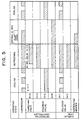
- Fig. 5 is a timing chart for explaining the operation of the cooling device, including the low temperature display case of the present invention;
- Fig. 6 is a vertical cross sectional side view of a low temperature display case according to another embodiment of the present invention;
- Fig. 7 is a refrigerant circuit diagram of a cooling device for cooling the low temperature display case shown in Fig. 6; and
- Fig. 8 is a vertical cross sectional side view of a conventional low temperature display case.
-
- The preferred embodiments of the present invention will now be described in detail while referring to the accompanying drawings. Fig. 1 is a perspective view of a low temperature display case 1 according to the present invention; Fig. 2 is a vertical cross sectional side view of the low temperature display case 1; Fig. 3 is a perspective view of an
evaporator 13; and Fig. 4 is a refrigerant circuit diagram for a cooling device R for cooling the low temperature display case 1. - The low temperature display case 1 of the present invention is a refrigerating openfront display case that is installed in a store, such as a supermarket or a convenience store, to display chilled confections, such as ice cream, that are for sale. The low temperature display case 1 has a substantially C shaped
heat insulation wall 2, andside plates 5 that are attached to both sides of theinsulation wall 2. Heatinsulation division wall 3, which is substantially C shaped, is so mounted inside theheat insulation wall 2 that there is an intervening space between them. Apartition panel 4 is provided inside the upper portion of the heatinsulation division wall 3 and extends outward, describing an intervening space. Deck struts 6 are provided at both ends and in the center of thepartition panel 4. - The lower ends of the deck struts 6 and of the
partition panel 4 are secured either directly or via another member to ametal fitting 7, the ends of which are fixed to frames (not shown) on either side of theheat insulation wall 2. In front of the lower portion of thepartition panel 4, adeck pan 8 is provided, with an intervening space, above abottom wall 3A of the heatinsulation division wall 3. Astorage chamber 9, which is open to the front, is defined by an area enclosed by thepartition panel 4 and thedeck pan 8. An outer duct 11 that is formed between theheat insulation wall 2 and the heatinsulation division wall 3, and aninner duct 12 that is formed between the heatinsulation division wall 3 and thepartition panel 4 and thedeck pan 8, communicate with the upper, the rear and the lower portions of thestorage chamber 9. - An
evaporator 13 that is included in a cooling device is provided upright at the rear inside theinner duct 12. As is shown in Fig. 3, theevaporator 13 comprises a plurality of aluminumheat exchange fins 31,tube sheets heat exchange fins 31; and a sinuously shapedrefrigerant pipe 36 that is passed through thetube sheets refrigerant pipe 36 has arefrigerant inlet 36A and arefrigerant outlet 36B at its left end near thetube sheet 32. - The
center tube sheet 33 and the rightend tube sheet 34, both of which are located away from therefrigerant inlet 36A, are made of an aluminum alloy that is a metal having high thermal conductivity. Thetube sheet 32 at the left end of therefrigerant pipe 36 is made of galvanized steel or stainless steel, as is a conventional one. This is because brazing is used to connect bent pipes to the refrigerant inlet andoutlet - The front lower ends of the
tube sheets evaporator 13 are fixed to themetal fitting 7. Themetal fitting 7 is also made of an aluminum alloy that is a metal having high thermal conductivity, and has a plurality of holes are formed in it. A suction blower 14 (for an inner duct) is provided below thedeck pan 108 in the front internal portion of theinner duct 12, and a suction blower 16 (for an outer duct) is provided in the front internal portion of the outer duct 11, which at that point is located below theinner duct 12. - The top surface of the
bottom wall 3A, of the heatinsulation division wall 3, inclines downward at an angle of 4 degrees, for example, toward adrain hole 17, which is located beneath theblower 14. The top face of thebottom wall 3A, therefore, serves as adrain pan 18, which is a drain guide face, and drain pan heaters (electric heaters) 19 for thedrain pan 18 are provided near thedrain hole 17, which communicates with the outer duct 11. Defrosting heaters (electric heaters) 22 and anattachment plate 21 are provided inside theinner duct 12 at the upper rear portion of thedrain pan 18. - When, during the defrosting operation, water from the evaporator 13 contacts the
defrosting heaters 22, the amount of heat generated is considerably reduced, and steam may be produced. Therefore, thedefrosting heaters 22 are located forward of theevaporator 13 and under themetal fitting 7, so that during defrosting, water falling from theevaporator 13 will not fall directly onto theheaters 22. Apart 22A, one of thedefrosting heaters 22, is located near themetal fitting 7. - A
slope member 38 is provided as an inclined portion on thedrain pan 18 at a position that is directly beneath theevaporator 13. Theslope member 38 is made of stainless steel, and its surface is inclined downward toward thedrain hole 17 at an inclination angle that is greater than that of thedrain pan 18. Theslope member 38 is mounted on, and extends from one side to the other of thedrain pan 18. With this arrangement, the surface of theslope member 38 is positioned near thedefrosting heaters 22. - Although the inclination portion is made of an
independent slope member 38 in this embodiment, it may be formed as an integral part of the heatinsulation division wall 3. - Further,
heat insulation material 39, foamed styrol, is used to fill the slope member 38 (adjacent to the heat insulation division wall 3), and apart 19A, one of thedrain pan heaters 19, is located near theslope member 38. - The upper ends of the inner and
outer ducts 12 and 11 communicate respectively with aninner discharge opening 24 and anouter discharge opening 26, which are positioned near the upper edge of the open side of thestorage chamber 9. Aninner intake opening 27 and anouter intake opening 28 are formed at the lower edge of the open side of thestorage chamber 9. From the front, theinner intake opening 27 is located behind theouter intake opening 28. Theinner intake opening 27 communicates with theinner duct 12, and theouter intake opening 28 communicates with the outer duct 11. - A defrost
recovery temperature sensor 40 for thedefrosting heaters 22 is provided at the upper portion of the inner duct 12 (upstream of the inner discharge opening 24).Decks 29 are supported by thestrut 6 as a series of steps, and frozen foods, such as ice cream, are displayed on thedecks 29. - In a refrigerant circuit shown in Fig. 4, a cooling device R comprises a condensing
unit 41; a circuit for the low temperature display case 1; a hot gas (high temperature refrigerant) defrosting circuit (hereinafter referred to as a defrost controller) 42; anaccumulator 52; and an ejectionpressure adjustment valve 56. - The condensing
unit 41 includes acompressor 43; acondenser 44; ablower 46 for a condenser; and afluid reservoir 47. The circuit for the display case 1 includes the above describedevaporator 13; anexpansion valve 53; solenoid valves SV1 and SV3; and a defrostrecovery temperature sensor 54 for thedefrost controller 42. - The
defrost controller 42 has aheat storage tank 38; an intakepressure adjustment valve 49; a three-way valve SV2; solenoid valves SV5, SV6 and SV4; andcheck valves compressor 43 communicates with theheat storage tank 48 and is connected to the inlet (A) of the three-way valve SV2. The outlet (C) of the three-way valve SV2 is connected to thecondenser 44, which communicates with thefluid reservoir 47. - The
fluid reservoir 47 is connected to the solenoid valve SV1 via thecheck valve 51 and a high pressure refrigerant pipe 60. The solenoid valve SV1 is connected to therefrigerant inlet 36A of theevaporator 13 via theexpansion valve 53. The heat sensing portion of theexpansion valve 53 is attached to therefrigerant outlet 36B of theevaporator 13, and the solenoid valve SV3 is connected in parallel so as to short circuit theexpansion valve 53. The defrostrecovery temperature sensor 54 is attached to therefrigerant outlet 36B of therefrigerant pipe 36 for theevaporator 13. - The
refrigerant outlet 36B of theevaporator 13 is connected to the intakepressure adjustment valve 49 via the solenoid valve SV6, and the pipe from the intakepressure adjustment valve 49 is passed through theheat storage tank 48 and is connected to theaccumulator 52. Theaccumulator 52 is connected to the intake side of thecompressor 43. - The solenoid valve SV5 short-circuits the solenoid valve SV6, the intake
pressure adjustment valve 49, and theheat storage tank 48. The outlet (B) of the three-way valve SV2 is connected via thecheck valve 50 to the high pressure refrigerant pipe 60 on the outlet side of thecheck valve 51. Further, the outlet (C) of the threeway valve SV2 and the inlet of the solenoid valve SV6 communicate with each other via the solenoid valve SV4. In addition, the ejectionpressure adjustment valve 56 is connected between the discharge side of thecompressor 43 and the outlet (C) of the three-way valve SV2. - An explanation will now be given for the operations performed by the thus arranged cooling device R, including the low temperature display case 1, while referring to the timing chart in Fig. 5. During the cooling operation, a controller (not shown) sets a flow path across the threeway valve SV2 from A to C, and the solenoid valves SV4, SV6 and SV3 are closed. The solenoid valve SV5 is opened, and when the temperature in the
storage chamber 9 in the low temperature display case 1 (or the discharged cool air temperature) becomes high, the solenoid valve SV1 is opened. - Under these conditions, when the
compressor 43 is activated to drive theblowers compressor 43 is passed through theheat storage tank 48 and flows via the three-way valve SV2 to thecondenser 44 along pipes represented in Fig. 4 by open parallel lines. The refrigerant is cooled by theblower 46 and the heat is released, and as a result, the refrigerant gas is condensed and liquefied. The refrigerant that has been condensed by thecondenser 44 is separated from uncondensed refrigerant gas in thefluid reservoir 47, and only liquid refrigerant is fed through thecheck valve 51, the high pressure refrigerant pipe 60, and the solenoid valve SV1 to theexpansion valve 53. - When the liquid refrigerant reaches and passed through the
expansion valve 53, the pressure on it is reduced, and it flows through therefrigerant pipe 36 to theevaporator 13 where it is vaporized and cooling function is performed. The air that is drawn in by theblower 14 is impelled toward theevaporator 13. The air that is cooled by heat exchange while passing through theevaporator 13, and rises along theinner duct 12 until it is discharged, toward the front opening of thestorage chamber 9, from theinner discharge opening 24, which is formed at the upper edge of the front opening. As a result, a curtain of cooled air covers the front opening of thestorage camber 9, while part of the cooled air circulates through thestorage chamber 9 and cools that area. - The air that is drawn in by the
blower 16 rises along the outer duct 11, and is discharged, toward the front opening of thestorage chamber 9, from theouter discharge opening 26, which is formed at the upper edge of the front opening. Thus, a protective air curtain is formed outside the curtain of cooled air. - The refrigerant is discharged from the
refrigerant outlet 36B of theevaporator 13, and flows through the solenoid valve SV5 to theaccumulator 52. In theaccumulator 52, unvaporized liquid refrigerant is separated from the refrigerant in the gaseous form, and only refrigerant in the gaseous form is fed into thecompressor 43. - When the temperature in the
storage chamber 9 has fallen to, for example, -21°C during the cooling operation, the controller closes the solenoid valve SV1 in accordance with the output of a temperature sensor (not shown). Since the flow of the refrigerant to theevaporator 13 is interrupted, the cooling function performed by theevaporator 13 is halted. The intake pressure at thecompressor 43 is thereafter reduced and thecompressor 43 is halted by a low pressure switch (not shown). - When the temperature in the
storage chamber 9 has risen to, for example, -19°C, the controller opens the solenoid valve SV1. Accordingly, the intake pressure at thecompressor 43, thecompressor 43 is activated, and the cooling cycle is begun. By repeating the above process, on average, thestorage chamber 9 is maintained at a refrigerating temperature of -20°C. - During the cooling operation, frost builds up on the
evaporator 13 and in theinner duct 12. To dispel this frost, while theblowers defrosting heaters 22 and thedrain pan heater 19A conductive. Theevaporator 13 is heated by warm air that is blown across it by theblower 14, and thedrain pan 18 is also heated. When the defrosting operation is begun, the solenoid valves SV1, SV4, SV6 and SV3 are opened and the solenoid valve SV5 is closed. - During the period when the pressure in the
evaporator 13 is brought low by opening the solenoid valve SV4, refrigerant at a high temperature flows from thecondenser 44 to theevaporator 13. After a time delay of 30 seconds following the start of the defrosting operation, the controller switches the three-way valve SV2 so that the flow path is from A to B. - Consequently, refrigerant gas that is discharged at a high temperature and under high pressure from the
compressor 43 is passed through theheat storage tank 48, the three-way valve SV2, thecheck valve 51, the high pressure refrigerant pipe 60 and the solenoid valves SV1 and SV3, bypasses theexpansion valve 53, and enters theevaporator 13 through therefrigerant inlet 36A. - As a consequence of the inflow of the high temperature refrigerant, the
evaporator 13 is heated from the inside, and the frost is thawed by warm air from thedefrosting heaters 22. Theevaporator 13, therefore, is gradually defrosted. The refrigerant that has heated theevaporator 13 and has been discharged form therefrigerant outlet 36B of theevaporator 13 is fed through the solenoid valve sV6 to the intakepressure adjustment valve 49. The pressure on the refrigerant is adjusted, and the refrigerant is thereafter vaporized in theheat storage tank 48 and flows to theaccumulator 52. Unvaporized liquid refrigerant is separated in the same manner as is described above, and only refrigerant in the gaseous form is drawn in by thecompressor 43. - Although during the defrosting, water that falls from the
evaporator 13 and ice are present on the surface of theslope member 38, the inclination of theslope member 38 is so sharp that the water flows smoothly toward thedrain hole 17 in thedrain pan 18 and is discharged to the exterior. Since the surface of theslope member 38 is located near thedefrosting heaters 22, the temperature at the surface rises until it is 0 C or higher. In addition, since thepart 19A, one of thedrain pan heaters 19, is also located near theslope member 38, the refreezing of the water that is produced when frost is thawed can be inhibited in theinner duct 12 below theevaporator 13, and incomplete defrosting can therefore be prevented. - Since the
metal fitting 7 is fixed to thetube sheets evaporator 13, it is strongly affected by the cooling function of theevaporator 13. As a result, frost tends to build up on themetal fitting 7, and water that falls from the top of theevaporator 13 tends to be retained there. - However, in the present invention, since the
tube sheets evaporator 13 are made of an aluminum alloy, heat is smoothly transmitted via therefrigerant pipe 36 to themetal fitting 7. And since themetal fitting 7 is also formed of an aluminum alloy and is positioned near thedefrosting heater 22A, the metal fitting is adequately heated. - At the
metal fitting 7, where residual frost tends to accumulate, the frost is rapidly thawed, and as a plurality of holes are formed in themetal fitting 7, water also falls smoothly. The problem posed by the incomplete defrosting of themetal fitting 7 is resolved, and the danger that therefrigerant pipe 36 may be broken is eliminated. Although thetube sheet 32 on therefrigerant inlet 36A is not formed of an aluminum alloy, there is abundant heat at that point because refrigerant at a high temperature flows in through theinlet 36A and prevents the occurrence of incomplete defrosting. - Further, as is described above, since the
drain pan heaters 19 are also rendered conductive during the defrosting, water that falls on thedrain pan 18 can be prevented from refreezing, and frost and ice on other portions in the inner duct can be thawed. - When six to eight minutes have elapsed following the beginning of the defrosting operation, the defrosting of the
evaporator 13 is terminated, and the temperature of theoutlet 36B is raised to, for example, +10°C. When that is detected by the defrostrecovery temperature sensor 54, the controller terminates the defrosting operation, begins a 6minute dripping operation whereby the threeway SV2 is switched so that the flow path is from A to C, the solenoid valves SV4, SV5, SV3 and SV1 are closed, and the collection of refrigerant in theevaporator 13 is begun by beginning a pumping down operation. - The air temperature in the
inner duct 12 does not rise to +10°C when the temperature at theoutlet 36B of theevaporator 13 is raised to +10°C. Based on the defrostrecovery temperature sensor 40, the controller maintains thedefrosting heaters 22 in the conductive state until the air temperature in theinner duct 12 rises to, for example, +10°C. Therefore, even after the defrosting operation is terminated, thedefrosting heaters 22 are continuously generating heat. - On the other hand, the temperature in the
evaporator 14 is reduced at the start of the pumping down operation, and accordingly, the air temperature in theinner duct 12 is temporarily reduced. If heat generation by thedefrosting heaters 22 were halted at this time, the temperature at theevaporator 13 would not be increased much, and incomplete defrosting would occur. As is described above, however, since thedefrosting heaters 22 continue to generate heat, the air temperature in theinner duct 12, which is temporarily reduced at the start of the pumping down operation, rises again. As a result, the problem that arises when water remaining on theevaporator 13 is refrozen does not occur. - When the intake pressure of the
compressor 43 is reduced, and thecompressor 43 is halted by a low voltage switch (not shown), as is described above, the pumping down operation is terminated. Thereafter, when the air temperature of theinner duct 12 is increased to +10°C by the heat generated by thedefrosting heaters 22, based on the output of the defrostrecovery temperature sensor 40, the controller halts the power supply to thedefrosting heaters 22. - Since the
drain pan heaters 19 generate heat during the dripping period, the refreezing of water on thedrain pan 18 can be prevented. When the 6minute dripping period has elapsed, the controller closes the solenoid valve SV6 and opens the solenoid valve SV5 to restart the above described cooling operation. - As is described above, the defrost
recovery temperature sensor 54, for detecting the temperature at theoutlet 36B of theevaporator 13, and the defrostrecovery temperature sensor 40, for detecting the air temperature in theinner duct 12, are employed to independently control the time at which the supply to theevaporator 13 of gaseous refrigerant at a high temperature is halted, and the time at which the generation of heat by thedefrosting heaters 22 is halted. Incomplete defrosting in the vicinity of theevaporator 13 is prevented, and compared with a conventional cooling device where defrosting heaters are conductive during a dripping period, the increase in the air temperature in theinner duct 12 can be controlled. Therefore, the minimum amount of heat is required for defrosting, and the temperature increase in thestorage chamber 9 is reduced to the minimum. - The time at which defrosting using the high temperature refrigerant gas is terminated varies depending on seasonal changes in the ambient temperature of the condensing
unit 41. Since the amount of heat generated by thedefrosting heaters 22 is constant, an almost constant time can be set for halting the power supply to thedefrosting heater 22 in accordance with the defrostrecovery temperature sensor 40. - Figs. 6 and 7 are refrigerant circuit diagrams for a low temperature display case and a cooling device R according to another embodiment. The same reference numerals as are used in Figs. 1 through 5 are also used in Figs. 6 and 7 to denote corresponding or identical components. In this embodiment, one part of a high pressure refrigerant pipe 60 that extends from a
check valve 50 through a solenoid valve SV1 is employed as adrawing pipe 61, which is attached to the internal face of aslope member 38. - With this structure, since the
slope member 38 is heated by refrigerant at a high temperature that flows through the drawingpipe 61, of the high pressure refrigerant pipe 60, frost will not build up on the surface of theslope member 38 during the cooling operation. During the defrosting operation, refreezing of water that falls from above can be more effectively prevented, and incomplete defrosting can be inhibited. - The
slope member 38 need not be provided across the entire width of theinner duct 12. A great amount of heat is provided at aninlet 36A of anevaporator 13 because theinlet 36A is the point at which the refrigerant at a high temperature flows. Theslope member 38 is not required in this portion. When theslope member 38 is not extended to the portion, therefrigerant inlet 36A andoutlet 36B can be easily provided for theevaporator 13. - As is described above, according to the present invention, in a low temperature display case wherein a refrigerant at a high temperature is supplied to an evaporator, and defrosting heaters, which are located in a duct at a forward position that is not under the evaporator, generate heat to defrost the evaporator, a slope member (inclined portion) is so provided on a drain pan (on the inclined surface of the drain pan), at a position below the evaporator, that it is inclined toward a drain hole at a greater angle than is the drain pan. Water and ice that falls during the defrosting of the evaporator is smoothly discharged through the drain hole.
- Contrary to a conventional device, the surface of the slope member is positioned near the defrosting heaters, and is strongly affected by the heat produced by them. Therefore, the refreezing of water on the drain pan under the evaporator can be prevented. According to the present invention, the water generated during defrosting can be fully discharged, and the degradation of the cooling ability due to residual frost can be prevented.
- Since a pipe within which a high temperature refrigerant circulates is attached to the slope member, frost does not build up on the surface of the slope member during cooling. Also, during defrosting, the refreezing of water that falls from above can be effectively prevented, and incomplete frosting can be inhibited.
- One part of the defrosting heaters is provided near the position where residual frost tends to accumulate. Since one of the defrosting heaters is provided near the metal fitting, as is described above, frost on the metal fitting can be completely thawed at a position that is less affected by heat from the high temperature refrigerant that flows through the evaporator. Incomplete frosting can thus be inhibited.
- Since the tube sheets of the evaporator are formed of metal having highly thermal conductivity, the heat from the high temperature refrigerant that flows through the evaporator can be effectively transmitted to peripheral components that are fixed to the tube sheets. Incomplete frosting around the evaporator can thus be inhibited.
- Further, since the metal fitting that is secured to the lower front end of the tube sheet of the evaporator is made of metal having highly thermal conductivity, the heat from the high temperature refrigerant that flows through the evaporator can be effectively transmitted to the metal fitting where frost tends to accumulate. Incomplete frosting around the evaporator can thus be inhibited.
- In addition, since one of the defrosting heaters is located near the metal fitting, the heat produced by the defrosting heater can prevent the retention of residual frost on the metal fitting.
Claims (5)
- A low temperature display case (1) comprising:wherein to defrost said evaporator (13) a refrigerant at a high temperature is fed into said evaporator (13), and heat is generated by said defrosting heaters (22).an outer duct (11) that is so formed that it communicates with a rear and a lower portion of a storage chamber (9) having an opening at the front,an evaporator (13) that is provided upright in an inner duct (12) at a rear location, a blower (14) for discharching, from an upper edge of said opening of said storage chamber (9), air that is cooled at said evaporator (13) by heat exchange,a drain guide face (18) that is located at a bottom level of said inner duct (12) and that is inclined downward toward a drain hole (17);defrosting heaters (22) that are provided in a lower portion of said inner duct (12) and that are located forward of a position under said evaporator (13),a sharply sloped portion (38) that is provided on said drain guide face (18) below said evaporator and that is inclined at a greater angle toward said drain hole (17) than is said drain guide face (18); anda pipe (60, 61) along which said high temperature refrigerant circulates that is attached to said sharply sloped portion (38),
- A low temperature display case according to claim 1, wherein one part of said defrosting heaters (22) is located close to a position where incomplete defrosting tends to occur.
- A low temperature display case according to claim 1, wherein a tube sheet (33, 34) for said evaporator (13) is made of a metal having high thermal conductivity.
- A low temperature display case according to claim 3, wherein a metal strut fitting, which is fixed to front lower ends of said tube sheet of said evaporator, is made of a metal having high thermal conductivity.
- A low temperature display case according to claim 4, wherein one part of said defrosting heaters (22) is located near said metal strut fitting.
Applications Claiming Priority (3)
| Application Number | Priority Date | Filing Date | Title |
|---|---|---|---|
| JP28924695A JP3177428B2 (en) | 1995-10-11 | 1995-10-11 | Low temperature showcase |
| JP289246/95 | 1995-10-11 | ||
| JP28924695 | 1995-10-11 |
Publications (3)
| Publication Number | Publication Date |
|---|---|
| EP0768053A2 EP0768053A2 (en) | 1997-04-16 |
| EP0768053A3 EP0768053A3 (en) | 1998-01-07 |
| EP0768053B1 true EP0768053B1 (en) | 2002-02-06 |
Family
ID=17740675
Family Applications (1)
| Application Number | Title | Priority Date | Filing Date |
|---|---|---|---|
| EP96116179A Expired - Lifetime EP0768053B1 (en) | 1995-10-11 | 1996-10-09 | Low temperature display case |
Country Status (7)
| Country | Link |
|---|---|
| US (1) | US5761922A (en) |
| EP (1) | EP0768053B1 (en) |
| JP (1) | JP3177428B2 (en) |
| KR (1) | KR100186665B1 (en) |
| DE (1) | DE69619050T2 (en) |
| DK (1) | DK0768053T3 (en) |
| ES (1) | ES2171586T3 (en) |
Families Citing this family (23)
| Publication number | Priority date | Publication date | Assignee | Title |
|---|---|---|---|---|
| FR2786999B1 (en) | 1998-12-09 | 2001-02-23 | Nevoret Concept | REFRIGERATION SALES FURNITURE |
| DE10140889A1 (en) * | 2001-08-21 | 2003-03-06 | Linde Ag | Novel cooling rack |
| US6519962B1 (en) * | 2002-06-27 | 2003-02-18 | Carrier Corporation | Refrigerated merchandiser angular air guide vanes |
| JP2005156117A (en) * | 2003-11-28 | 2005-06-16 | Sanyo Electric Co Ltd | Showcase |
| JP2006046694A (en) * | 2004-07-30 | 2006-02-16 | Daikin Ind Ltd | Refrigeration equipment |
| KR100597748B1 (en) * | 2004-08-27 | 2006-07-07 | 삼성전자주식회사 | Refrigeration system |
| JP2007260223A (en) * | 2006-03-29 | 2007-10-11 | Sanyo Electric Co Ltd | Open showcase |
| CA2552454A1 (en) * | 2006-07-17 | 2008-01-17 | W. C. Wood Company Limited | Frost management system for a refrigerated cabinet |
| JP4895848B2 (en) * | 2007-02-08 | 2012-03-14 | 三洋電機株式会社 | Cooling system |
| JP4935480B2 (en) * | 2007-04-19 | 2012-05-23 | 富士電機株式会社 | Cooling system |
| JP2010057806A (en) * | 2008-09-05 | 2010-03-18 | Sanyo Electric Co Ltd | Low temperature showcase |
| JP5258463B2 (en) * | 2008-09-05 | 2013-08-07 | 三洋電機株式会社 | Low temperature showcase |
| EP3330642B1 (en) * | 2010-05-26 | 2020-04-29 | Mitsubishi Electric Corporation | Refrigerating and air-conditioning apparatus |
| JP5789755B2 (en) * | 2010-11-30 | 2015-10-07 | パナソニックIpマネジメント株式会社 | Refrigeration equipment |
| GB2482073A (en) * | 2011-09-15 | 2012-01-18 | David Turner | A System And Method To Reduce Refrigerated Air Leaving An Open Deck Display Cabinet. |
| US20120227424A1 (en) * | 2011-03-10 | 2012-09-13 | Prince Castle LLC | Converging/Diverging Front Intake |
| DE102012107712A1 (en) * | 2012-08-22 | 2014-02-27 | Aht Cooling Systems Gmbh | refrigerated |
| US9687088B2 (en) * | 2013-04-08 | 2017-06-27 | Heatcraft Refrigeration Products Llc | Deflector for display cases |
| WO2015062662A1 (en) * | 2013-10-31 | 2015-05-07 | Arcelik Anonim Sirketi | Refrigerator with an improved defrost circuit and method for controlling the refrigerator |
| US10646054B2 (en) * | 2016-03-31 | 2020-05-12 | Panasonic Intellectual Property Management Co., Ltd. | Showcase and operation method thereof |
| CN106949658A (en) * | 2017-03-17 | 2017-07-14 | 广东美的制冷设备有限公司 | The control method of air-conditioner and air-conditioner |
| CN108420239A (en) * | 2017-09-20 | 2018-08-21 | 汝州市中鼎科技有限公司 | A kind of automatic thermostat sea food display cabinet convenient for deicing |
| CN115127284A (en) * | 2022-07-07 | 2022-09-30 | 合肥美菱物联科技有限公司 | Refrigerator defrosting system and defrosting method |
Family Cites Families (9)
| Publication number | Priority date | Publication date | Assignee | Title |
|---|---|---|---|---|
| US2513675A (en) * | 1947-01-17 | 1950-07-04 | Russell F Petersen | Open display refrigerated case |
| US3182466A (en) * | 1962-03-22 | 1965-05-11 | Dual Jet Refrigeration Company | Conditioned storage cabinet |
| DE1197105B (en) * | 1962-11-09 | 1965-07-22 | Martin Gabler | Process for generating low temperatures in the compartments of a refrigerated shelf and refrigerated shelf operating according to this method |
| US4117698A (en) * | 1977-06-29 | 1978-10-03 | Kysor Industrial Corporation | Refrigerated display |
| US4690209A (en) * | 1985-03-18 | 1987-09-01 | Martin Cory I | Air conditioner evaporator system |
| GB8813051D0 (en) * | 1988-06-02 | 1988-07-06 | Craig Nocol Ltd | Refrigeration system |
| JPH0221177A (en) * | 1988-07-07 | 1990-01-24 | Fuji Electric Co Ltd | Defrosting system for chilled-air circulation type open showcase |
| JP2547926B2 (en) * | 1992-08-18 | 1996-10-30 | 富士電機株式会社 | How to defrost a frozen / refrigerated open showcase |
| US5475988A (en) * | 1994-11-17 | 1995-12-19 | Delaware Capital Formation Inc. | Refrigerated display case with an improved air flow control and a contaminant control apparatus |
-
1995
- 1995-10-11 JP JP28924695A patent/JP3177428B2/en not_active Expired - Fee Related
-
1996
- 1996-10-09 DK DK96116179T patent/DK0768053T3/en active
- 1996-10-09 KR KR1019960044743A patent/KR100186665B1/en not_active Expired - Fee Related
- 1996-10-09 EP EP96116179A patent/EP0768053B1/en not_active Expired - Lifetime
- 1996-10-09 DE DE69619050T patent/DE69619050T2/en not_active Expired - Lifetime
- 1996-10-09 ES ES96116179T patent/ES2171586T3/en not_active Expired - Lifetime
- 1996-10-11 US US08/731,347 patent/US5761922A/en not_active Expired - Fee Related
Also Published As
| Publication number | Publication date |
|---|---|
| EP0768053A3 (en) | 1998-01-07 |
| ES2171586T3 (en) | 2002-09-16 |
| US5761922A (en) | 1998-06-09 |
| EP0768053A2 (en) | 1997-04-16 |
| KR970022124A (en) | 1997-05-28 |
| JP3177428B2 (en) | 2001-06-18 |
| DE69619050D1 (en) | 2002-03-21 |
| KR100186665B1 (en) | 1999-10-01 |
| DK0768053T3 (en) | 2002-05-27 |
| DE69619050T2 (en) | 2002-11-21 |
| JPH09113103A (en) | 1997-05-02 |
Similar Documents
| Publication | Publication Date | Title |
|---|---|---|
| US5761922A (en) | Low temperature display case | |
| EP0768501B1 (en) | A defrosting method for a low temperature display case and low temperature display case | |
| US4459826A (en) | Refrigerator | |
| CA2180113C (en) | Defrosting apparatus for refrigerators and method for controlling the same | |
| JP3688892B2 (en) | Freezer refrigerator | |
| US20080092569A1 (en) | Cooling unit with multi-parameter defrost control | |
| CN104160225A (en) | Refrigerator and working method thereof | |
| KR20020084688A (en) | Medium temperature refrigerated merchandiser | |
| US5207761A (en) | Refrigerator/water purifier with common evaporator | |
| US3638449A (en) | Refrigeration apparatus | |
| US5715689A (en) | Evaporator for combination refrigerator/freezer | |
| US20110252816A1 (en) | Refrigerator icemaker moisture removal and defrost assembly | |
| EP1334321B1 (en) | A defrosting method and a refrigeration appliance using thereof | |
| JP3649875B2 (en) | Low temperature showcase | |
| JP3086181B2 (en) | Cooling storage | |
| US3683636A (en) | Refrigeration system defrosting means | |
| KR100674531B1 (en) | Non implantable cooling system | |
| JP3942455B2 (en) | Refrigerator | |
| JP6330137B2 (en) | refrigerator | |
| CN1155647A (en) | Low temperature gondola | |
| CN101135527A (en) | Cooling storage shed | |
| JPH09269179A (en) | Defroster for refrigerator | |
| JP2008051368A (en) | Cooling unit and storage with cooling unit | |
| JP2024054945A (en) | Ice maker | |
| JP2015025566A (en) | refrigerator |
Legal Events
| Date | Code | Title | Description |
|---|---|---|---|
| PUAI | Public reference made under article 153(3) epc to a published international application that has entered the european phase |
Free format text: ORIGINAL CODE: 0009012 |
|
| AK | Designated contracting states |
Kind code of ref document: A2 Designated state(s): BE DE DK ES FR GB IT |
|
| PUAL | Search report despatched |
Free format text: ORIGINAL CODE: 0009013 |
|
| AK | Designated contracting states |
Kind code of ref document: A3 Designated state(s): BE DE DK ES FR GB IT |
|
| 17P | Request for examination filed |
Effective date: 19980626 |
|
| 17Q | First examination report despatched |
Effective date: 19991001 |
|
| GRAG | Despatch of communication of intention to grant |
Free format text: ORIGINAL CODE: EPIDOS AGRA |
|
| GRAG | Despatch of communication of intention to grant |
Free format text: ORIGINAL CODE: EPIDOS AGRA |
|
| GRAH | Despatch of communication of intention to grant a patent |
Free format text: ORIGINAL CODE: EPIDOS IGRA |
|
| GRAH | Despatch of communication of intention to grant a patent |
Free format text: ORIGINAL CODE: EPIDOS IGRA |
|
| GRAA | (expected) grant |
Free format text: ORIGINAL CODE: 0009210 |
|
| REG | Reference to a national code |
Ref country code: GB Ref legal event code: IF02 |
|
| AK | Designated contracting states |
Kind code of ref document: B1 Designated state(s): BE DE DK ES FR GB IT |
|
| REF | Corresponds to: |
Ref document number: 69619050 Country of ref document: DE Date of ref document: 20020321 |
|
| ET | Fr: translation filed | ||
| REG | Reference to a national code |
Ref country code: DK Ref legal event code: T3 |
|
| REG | Reference to a national code |
Ref country code: ES Ref legal event code: FG2A Ref document number: 2171586 Country of ref document: ES Kind code of ref document: T3 |
|
| PLBE | No opposition filed within time limit |
Free format text: ORIGINAL CODE: 0009261 |
|
| STAA | Information on the status of an ep patent application or granted ep patent |
Free format text: STATUS: NO OPPOSITION FILED WITHIN TIME LIMIT |
|
| 26N | No opposition filed |
Effective date: 20021107 |
|
| PGFP | Annual fee paid to national office [announced via postgrant information from national office to epo] |
Ref country code: ES Payment date: 20091026 Year of fee payment: 14 Ref country code: DK Payment date: 20091023 Year of fee payment: 14 |
|
| PGFP | Annual fee paid to national office [announced via postgrant information from national office to epo] |
Ref country code: IT Payment date: 20091023 Year of fee payment: 14 Ref country code: GB Payment date: 20091023 Year of fee payment: 14 Ref country code: FR Payment date: 20091110 Year of fee payment: 14 |
|
| PGFP | Annual fee paid to national office [announced via postgrant information from national office to epo] |
Ref country code: BE Payment date: 20091029 Year of fee payment: 14 |
|
| PGFP | Annual fee paid to national office [announced via postgrant information from national office to epo] |
Ref country code: DE Payment date: 20091218 Year of fee payment: 14 |
|
| BERE | Be: lapsed |
Owner name: *SANYO ELECTRIC CO. LTD Effective date: 20101031 |
|
| REG | Reference to a national code |
Ref country code: DK Ref legal event code: EBP |
|
| GBPC | Gb: european patent ceased through non-payment of renewal fee |
Effective date: 20101009 |
|
| PG25 | Lapsed in a contracting state [announced via postgrant information from national office to epo] |
Ref country code: FR Free format text: LAPSE BECAUSE OF NON-PAYMENT OF DUE FEES Effective date: 20101102 |
|
| REG | Reference to a national code |
Ref country code: FR Ref legal event code: ST Effective date: 20110630 |
|
| PG25 | Lapsed in a contracting state [announced via postgrant information from national office to epo] |
Ref country code: GB Free format text: LAPSE BECAUSE OF NON-PAYMENT OF DUE FEES Effective date: 20101009 Ref country code: BE Free format text: LAPSE BECAUSE OF NON-PAYMENT OF DUE FEES Effective date: 20101031 |
|
| REG | Reference to a national code |
Ref country code: DE Ref legal event code: R119 Ref document number: 69619050 Country of ref document: DE Effective date: 20110502 |
|
| PG25 | Lapsed in a contracting state [announced via postgrant information from national office to epo] |
Ref country code: DK Free format text: LAPSE BECAUSE OF NON-PAYMENT OF DUE FEES Effective date: 20101031 |
|
| REG | Reference to a national code |
Ref country code: ES Ref legal event code: FD2A Effective date: 20111118 |
|
| PG25 | Lapsed in a contracting state [announced via postgrant information from national office to epo] |
Ref country code: IT Free format text: LAPSE BECAUSE OF NON-PAYMENT OF DUE FEES Effective date: 20101009 |
|
| PG25 | Lapsed in a contracting state [announced via postgrant information from national office to epo] |
Ref country code: ES Free format text: LAPSE BECAUSE OF NON-PAYMENT OF DUE FEES Effective date: 20101010 |
|
| PG25 | Lapsed in a contracting state [announced via postgrant information from national office to epo] |
Ref country code: DE Free format text: LAPSE BECAUSE OF NON-PAYMENT OF DUE FEES Effective date: 20110502 |