EP0767458A2 - Verfahren und Gerät zum Erfassen und Anpassen der Aufzeichnungsgeschwindigkeit eines vorher aufgezeichneten Bands - Google Patents
Verfahren und Gerät zum Erfassen und Anpassen der Aufzeichnungsgeschwindigkeit eines vorher aufgezeichneten Bands Download PDFInfo
- Publication number
- EP0767458A2 EP0767458A2 EP96307067A EP96307067A EP0767458A2 EP 0767458 A2 EP0767458 A2 EP 0767458A2 EP 96307067 A EP96307067 A EP 96307067A EP 96307067 A EP96307067 A EP 96307067A EP 0767458 A2 EP0767458 A2 EP 0767458A2
- Authority
- EP
- European Patent Office
- Prior art keywords
- speed
- sector
- sector data
- synchronization
- header
- Prior art date
- Legal status (The legal status is an assumption and is not a legal conclusion. Google has not performed a legal analysis and makes no representation as to the accuracy of the status listed.)
- Ceased
Links
Images

Classifications
-
- G—PHYSICS
- G11—INFORMATION STORAGE
- G11B—INFORMATION STORAGE BASED ON RELATIVE MOVEMENT BETWEEN RECORD CARRIER AND TRANSDUCER
- G11B15/00—Driving, starting or stopping record carriers of filamentary or web form; Driving both such record carriers and heads; Guiding such record carriers or containers therefor; Control thereof; Control of operating function
- G11B15/18—Driving; Starting; Stopping; Arrangements for control or regulation thereof
- G11B15/46—Controlling, regulating, or indicating speed
- G11B15/52—Controlling, regulating, or indicating speed by using signals recorded on, or derived from, record carrier
Definitions
- the present invention relates generally to controlling the speed of a magnetic medium, such as magnetic tape, and more particularly to a method and apparatus for detecting and matching the recorded speed of a previously recorded magnetic medium.
- Digital data are conventionally stored on magnetic medium, such as magnetic tape, in the form of flux transitions on the surface of the medium.
- Data recovery consist of determining the presence, and relative timing, of such flux transitions.
- Optimal operation of a recording device therefore depends upon numerous factors, including but not limited to the proper orientation and speed of the magnetic tape and the proper orientation and position of the magnetic head. Otherwise, the information may be inaccurately retrieved even if the information was properly recorded. The integrity of the information storage system may be compromised and information may be lost.
- Optimizing cartridge tape speed is especially critical for certain products, such as Quarter-Inch Cartridge (QIC) tape drives.
- QIC tape drives only allow a long term speed variation of approximately +/- 3% of the nominal tape speed measured over a minimum of 2,000,000 transition cells.
- Conventional QIC tape drives utilize an open loop solution, which results in a long term speed variation of as much as +/- 6% of the nominal tape speed.
- the preceding and other shortcomings of prior art methods and systems are overcome by the present invention which provides a method and apparatus for detecting and matching the recorded speed of a previously recorded tape.
- An algorithm changes the commanded speed to a servo system to a speed that is centered between the speed at which the sector header was written and the sector data was written.
- the measured synchronization portion of the sector header is initially integrated with respect to time.
- the measured synchronization portion of the sector data is then integrated with respect to time.
- An optimum speed is computed based on the difference in the speeds at which they were recorded.
- the commanded speed to the servo system is then changed as a result of the previous step.
- the present invention provides, in a first aspect, a program storage device readable by a machine, tangibly embodying a program of instructions executable by the machine to perform method steps for detecting and matching the recorded speed of tape having sectors including sector headers recorded at a first speed and sector data recorded at a second speed.
- the method steps comprise integrating a specified portion of a synchronization portion of the sector header and the sector data with respect to time to determine a speed at which the sector header and the sector data was written, determining the difference between each of the sector header and the sector data measurements with respect to time, computing a statistical average based upon the difference to determine an optimum speed, and adjusting the commanded speed based on the optimum speed.
- the present invention provides a program storage device readable by a machine, tangibly embodying a program of instructions executable by the machine to perform method steps for detecting and matching the recorded speed of tape having sectors including sector headers recorded at a first speed and sector data recorded at a second speed.
- the method steps comprise integrating a specified portion of a synchronization portion of the sector header and the sector data with respect to time to determine a speed at which the sector header and the sector data was written, determining the difference between each of the sector header and the sector data measurements with respect to time, computing a statistical average based upon the difference to determine an optimum speed, and adjusting the commanded speed based on the optimum speed.
- the present invention provides an apparatus, comprising a computer usable medium having computer readable program code means embodied therein for causing detecting and matching the recorded speed of tape having sectors including sector headers recorded at a first speed and sector data recorded at a second speed.
- the computer readable program code means in the apparatus comprises computer readable program code means for causing a computer to integrate a specified portion of a synchronization portion of the sector header and the sector data with respect to time to determine a speed at which the sector header and the sector data was written, computer readable program code means for causing the computer to determine difference between each of the sector header and the sector data measurements with respect to time, computer readable program code means for causing the computer to compute a statistical average based upon the difference to determine an optimum speed, and computer readable program code means for causing the computer to adjust the commanded speed based on the optimum speed.
- FIG. 1 is a graphical representation of a magnetic tape portion 10 having multiple tracks 12 disposed longitudinally along the length of the tape 10 portion 10. The tracks 12 are written in parallel in the forward and reverse directions. Each track 12 is divided into multiple segments 14.
- FIG. 2 is a diagram of a general layout of one of the segments 14 located on the magnetic tape portion 10 shown in FIG. 1. Each segment 14 includes a segment header 16 followed by a plurality of sectors 18. In the preferred embodiment, each segment 14 is divided into thirty-two sectors 18. Each sector 18 is divided into a sector header 20 and sector data 22. Each sector data 22 is followed by the sector header 20 of the next sector 18. Address information, track number and sector number are stored into the sector header 20. Data are recorded in or retrieved from the sector data 22.
- the sector header 20 and sector data 22 each include a synchronization field 24 and 26, preferably eight bytes (96 bits) long, although the present invention may be adapted to be used with other field lengths as well.
- the sector headers 20 and sector data 22 are written at different speeds.
- the sector headers 20 and sector data 22 are written often at different densities, i.e. frequencies. Consequently, the long term speed variation may be as much as +/- 6% of the nominal tape speed measured over a minimum of 2,000,000 transition cells.
- QIC drives typically only allow a long term tape speed variation of approximately +/-3% of the nominal tape speed.
- the present invention provides an algorithm which may be implemented in a drive microprocessor for changing the commanded speed to a servo system to a speed that is centered between the speed at which the sector header 20 was written and the speed at which the sector data 22 was written. The algorithm thus centers the speed of the tape such that the read channel is at worst only approximately 3% off from the nominal value in both cases.
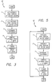
- FIG. 3 is a flow chart of an algorithm 30 which may be implemented in a drive microprocessor for detecting and matching the recorded speed of a previously recorded magnetic medium.
- step 1 the number of samples of sectors 18, n, is divided by 2 and the measured synchronization portion 24 of the sector header 20 is integrated with respect to time to determine the speed at which the sector header 20 was written.
- step 2 the number of samples of sectors 18, n, is divided by 2 and the measured synchronization portion 26 of the sector data 22 is integrated with respect to time to determine the speed at which the sector data 22 was written.
- the number of samples, n is equal to 1000, one-half of the samples will be sector headers 20 and the other one-half will be sector data 22.
- step 3 The difference between the sector header speed and the sector data speed is then computed (step 3) .
- E sync is equal to the sum of the synchronization differences between the sector header speed and the sector data speed
- n is equal to the number of samples i.e. sectors 18.
- the statistical average which is the sum of the synchronization differences over the number of samples of sectors 18, is computed.
- the commanded speed to the servo system is then changed accordingly based on the results from step 5.
- the first sector header synchronization field is measured, then the first sector data synchronization field is measured, then the second sector header synchronization field is measured followed by the second sector data synchronization field being measured, and so forth.
- the statistical average which is the sum of the synchronization differences over the number of samples, is then computed to change the speed of the servo system in accordance with equation (1), shown above.
- a synchronization counting circuit 40 may be used to detect the relative speed difference between the current speed and the recorded speed by measuring a specified portion of the sector header synchronization field 24 and the sector data synchronization field 26.
- the synchronization counting circuit 40 is clocked at a fixed rate and includes a state machine 42 and a synchronization counter 44, preferably an 8-bit counter.
- the clock for the circuit 40 is generated with a crystal and typically runs at sixteen times the data rate.
- the state machine 42 may be a commercially available or custom state machine.
- the counter 44 may be a conventional binary counter, such as an 8-bit binary counter manufactured by Texas Instruments.
- the read data input 46 is initially applied to the state machine 42, which includes an internal synchronization detector (not shown).
- the enable signal 48 for the counter 44 is provided by the synchronization detector in the state machine 42.
- the counter 44 is only clocked when the sector header 24 or sector data synchronization field 26 is being detected, in this case for 64-bits. After detection, the counter 44 stops clocking and the values which are left in the register maps are computed.
- the synchronization counting circuit 40 thus measures a specified portion of the sector header 24 or sector data synchronization field 26.
- the synchronization counting circuit 40 measures 64 bits of the 96 bit sector header 24 or sector data 26 synchronization field. The recorded bits are measured with respect to time.
- the present invention is not limited to measuring 64 bits but rather may measure as many bits as desired depending upon the particular configuration on hand.
- the tape In operation, when a tape, previously recorded at tape speed "x”, is placed into a different tape drive servoing at speed "x + 1%", the tape actually runs at a 1% faster rate than the recorded speed.
- the synchronization counting circuit 40 detects the difference between the recorded tape speed and the actual tape speed, in this case 1%.
- the commanded speed to the servo system is then changed in response to the detected tape speed difference. In this case, the actual speed is decreased to match the recorded speed, thus matching the actual data rate on the tape.
- the synchronization counter 44 is enabled for 8 bytes of synchronization.
- the 8 bytes will result in different synchronization count values depending on the actual speed of the tape.
- the perfect data speed is calculated in accordance with the following equation:
- Typical synchronization count values are shown in TABLE 1 as follows: TABLE 1 Speed Synchronization Count Values No. of Clocks Output of Counter Nominal 1024 100 0000 0000 10% Slow 1126 100 0110 0110 10% Fast 921 011 1001 1001
- the synchronization counting circuit 40 first measures the first sector header synchronization field, then the first sector data synchronization field, then the second sector header synchronization field followed by the second sector data synchronization field being measured, and so forth.
- the statistical average which is the sum of the synchronization differences over the number of samples, is then computed to change the speed of the servo system in accordance with equation (1), shown above.
- FIG. 5 is a flow chart of an algorithm 52 which may be implemented in a drive microprocessor for detecting and matching the recorded speed of a previously recorded magnetic medium.
- the measured synchronization portion 24 of the sector header 20 is integrated with respect to time to determine the speed at which the sector header 20 was written.
- the measured synchronization portion 26 of the sector data 22 is integrated with respect to time to determine the speed at which the sector data 22 was written.
- step 3 The difference between the sector header speed and the sector data speed is then computed (step 3).
- E sync equal to the sum of the synchronization differences between the sector header speed and the sector data speed
- n is equal to the number of samples.
- the statistical average which is the sum of the synchronization differences over the number of samples, is computed.
- the commanded speed to the servo system is then changed accordingly based on the results from step 5.
- the algorithm 52 loops back and continuously executes steps 1 through 5, thus generating a continuous running average which may be computed to continuously update the speed of the servo system.
Landscapes
- Signal Processing For Digital Recording And Reproducing (AREA)
Applications Claiming Priority (4)
| Application Number | Priority Date | Filing Date | Title |
|---|---|---|---|
| US644435 | 1984-08-27 | ||
| US471895P | 1995-10-02 | 1995-10-02 | |
| US4718 | 1995-10-02 | ||
| US08/644,435 US5771129A (en) | 1995-10-02 | 1996-05-13 | Method and apparatus for detecting and matching the recorded speed of previously recorded tape |
Publications (2)
| Publication Number | Publication Date |
|---|---|
| EP0767458A2 true EP0767458A2 (de) | 1997-04-09 |
| EP0767458A3 EP0767458A3 (de) | 1998-03-18 |
Family
ID=26673372
Family Applications (1)
| Application Number | Title | Priority Date | Filing Date |
|---|---|---|---|
| EP96307067A Ceased EP0767458A3 (de) | 1995-10-02 | 1996-09-27 | Verfahren und Gerät zum Erfassen und Anpassen der Aufzeichnungsgeschwindigkeit eines vorher aufgezeichneten Bands |
Country Status (3)
| Country | Link |
|---|---|
| US (1) | US5771129A (de) |
| EP (1) | EP0767458A3 (de) |
| JP (1) | JPH09171650A (de) |
Family Cites Families (7)
| Publication number | Priority date | Publication date | Assignee | Title |
|---|---|---|---|---|
| JPS58139354A (ja) * | 1982-02-15 | 1983-08-18 | Sony Corp | デイジタル信号記録再生装置 |
| JPH0673225B2 (ja) * | 1984-11-06 | 1994-09-14 | 株式会社日立製作所 | デイジタル情報再生装置における時間軸補正装置 |
| JP2513204B2 (ja) * | 1987-01-28 | 1996-07-03 | ソニー株式会社 | Pcm信号再生装置の速度制御回路 |
| US5088077A (en) * | 1988-11-10 | 1992-02-11 | Ampex Corporation | Synchronization of record media transports and tracking adjustment |
| US5379161A (en) * | 1993-06-14 | 1995-01-03 | International Business Machines Corporation | Method and system for synchronization character location and prediction in a data storage system |
| US5357380A (en) * | 1993-06-14 | 1994-10-18 | International Business Machines Corporation | Method and apparatus for indicating when each track is in burst in a multitrack tape device |
| DE19517509C2 (de) * | 1994-05-13 | 1997-05-15 | Hitachi Ltd | Schrägspur-Wiedergabegerät mit Spureinstellsteuerung zur schnellen Wiedergabe digitaler Informationssignale von Magnetbändern |
-
1996
- 1996-05-13 US US08/644,435 patent/US5771129A/en not_active Expired - Fee Related
- 1996-09-27 EP EP96307067A patent/EP0767458A3/de not_active Ceased
- 1996-10-01 JP JP8260620A patent/JPH09171650A/ja active Pending
Also Published As
| Publication number | Publication date |
|---|---|
| US5771129A (en) | 1998-06-23 |
| EP0767458A3 (de) | 1998-03-18 |
| JPH09171650A (ja) | 1997-06-30 |
Similar Documents
| Publication | Publication Date | Title |
|---|---|---|
| EP0562563B1 (de) | Format zum eingebetteter Servo-Information und Verfahren Mehrspuraufzeichnen | |
| CA2066189C (en) | Servo tracking for helical scan recorder | |
| US6512651B1 (en) | Helical scan tape track following | |
| EP0480483A2 (de) | Verfahren und System zur dynamischen Verstärkungskalibrierung eines Wiedergabeverstärkers mit variabler Verstärkung | |
| US6278571B1 (en) | Adaptive servo gap detection for timing based servo | |
| US20040141250A1 (en) | Servo pattern based tape tension control for tape drives | |
| EP0996114B1 (de) | Servosystem und Verfahren mit Multiphasentaktsignal | |
| US5771129A (en) | Method and apparatus for detecting and matching the recorded speed of previously recorded tape | |
| CA1104719A (en) | Read apparatus | |
| JPH11312208A (ja) | 絶対位置情報記録方法 | |
| KR100258403B1 (ko) | 데이타 레코더 및 그 작동방법 | |
| US6342983B1 (en) | Recording tape medium, and apparatus for recording data on and recorded data from recording tape medium by helical scanning system | |
| EP0671735B1 (de) | Verfahren und Gerät für die Bewegungssteuerung von Aufzeichnungsmedien | |
| WO2001037276A1 (en) | Appended data recording on magnetic tape | |
| JPH0714319A (ja) | 複数トラック磁気テープの処理方法および装置 | |
| EP0565367B1 (de) | Ein zur Datenrückgewinnung Standbildtechniken benutzendes Datenaufnahmeverfahren | |
| US5978338A (en) | Apparatus for reproducing short length data stored on an optical disk | |
| EP0789489A3 (de) | Anlage und Verfahren zur Fernsehsignal-Aufnahme und Wiedergabe für einen digitalen Fernsehkassettenrecorder | |
| EP1526527B1 (de) | Verfahren zur Justierung eines Spulentachometers unter Verwendung von Kontrolldatenpaketen | |
| JPH0346886B2 (de) | ||
| EP0173474A2 (de) | Verfahren und Vorrichtung zur Steuerung der Lage eines transportierten Bandes | |
| JP3320170B2 (ja) | 磁気テープ再生装置 | |
| JPH0684118A (ja) | 磁気記録再生方式 | |
| KR940020339A (ko) | 트랙킹 제어방법 및 그 장치 | |
| JPH07272233A (ja) | サーボ制御装置 |
Legal Events
| Date | Code | Title | Description |
|---|---|---|---|
| PUAI | Public reference made under article 153(3) epc to a published international application that has entered the european phase |
Free format text: ORIGINAL CODE: 0009012 |
|
| AK | Designated contracting states |
Kind code of ref document: A2 Designated state(s): DE FR GB IT NL |
|
| PUAL | Search report despatched |
Free format text: ORIGINAL CODE: 0009013 |
|
| AK | Designated contracting states |
Kind code of ref document: A3 Designated state(s): DE FR GB IT NL |
|
| 17P | Request for examination filed |
Effective date: 19980918 |
|
| 17Q | First examination report despatched |
Effective date: 19991229 |
|
| GRAG | Despatch of communication of intention to grant |
Free format text: ORIGINAL CODE: EPIDOS AGRA |
|
| STAA | Information on the status of an ep patent application or granted ep patent |
Free format text: STATUS: THE APPLICATION HAS BEEN REFUSED |
|
| 18R | Application refused |
Effective date: 20010628 |