EP0767361A2 - Verfahren und Vorrichtung zur Spektralanalyse - Google Patents
Verfahren und Vorrichtung zur Spektralanalyse Download PDFInfo
- Publication number
- EP0767361A2 EP0767361A2 EP93203737A EP93203737A EP0767361A2 EP 0767361 A2 EP0767361 A2 EP 0767361A2 EP 93203737 A EP93203737 A EP 93203737A EP 93203737 A EP93203737 A EP 93203737A EP 0767361 A2 EP0767361 A2 EP 0767361A2
- Authority
- EP
- European Patent Office
- Prior art keywords
- interferometer
- light
- scene
- detector array
- pixel
- Prior art date
- Legal status (The legal status is an assumption and is not a legal conclusion. Google has not performed a legal analysis and makes no representation as to the accuracy of the status listed.)
- Granted
Links
- 238000000034 method Methods 0.000 title claims abstract description 39
- 238000010183 spectrum analysis Methods 0.000 title description 5
- 230000003287 optical effect Effects 0.000 claims abstract description 76
- 230000003595 spectral effect Effects 0.000 claims abstract description 60
- 238000012545 processing Methods 0.000 claims abstract description 5
- 238000003384 imaging method Methods 0.000 description 38
- 230000005855 radiation Effects 0.000 description 25
- BJQHLKABXJIVAM-UHFFFAOYSA-N bis(2-ethylhexyl) phthalate Chemical compound CCCCC(CC)COC(=O)C1=CC=CC=C1C(=O)OCC(CC)CCCC BJQHLKABXJIVAM-UHFFFAOYSA-N 0.000 description 20
- 238000001228 spectrum Methods 0.000 description 17
- 230000006870 function Effects 0.000 description 13
- 239000011159 matrix material Substances 0.000 description 7
- 230000000694 effects Effects 0.000 description 6
- 238000005259 measurement Methods 0.000 description 6
- 230000008901 benefit Effects 0.000 description 5
- 230000035945 sensitivity Effects 0.000 description 5
- 230000009466 transformation Effects 0.000 description 5
- 238000004458 analytical method Methods 0.000 description 4
- 230000008859 change Effects 0.000 description 4
- 238000010586 diagram Methods 0.000 description 4
- 230000005540 biological transmission Effects 0.000 description 3
- 239000000463 material Substances 0.000 description 3
- 241000282461 Canis lupus Species 0.000 description 2
- 244000007853 Sarothamnus scoparius Species 0.000 description 2
- 238000010276 construction Methods 0.000 description 2
- 230000003247 decreasing effect Effects 0.000 description 2
- 238000005286 illumination Methods 0.000 description 2
- 230000010354 integration Effects 0.000 description 2
- 238000012986 modification Methods 0.000 description 2
- 230000004048 modification Effects 0.000 description 2
- 238000001530 Raman microscopy Methods 0.000 description 1
- 238000001069 Raman spectroscopy Methods 0.000 description 1
- 241000656145 Thyrsites atun Species 0.000 description 1
- 238000013459 approach Methods 0.000 description 1
- 238000003491 array Methods 0.000 description 1
- 230000000903 blocking effect Effects 0.000 description 1
- 238000004364 calculation method Methods 0.000 description 1
- 239000011248 coating agent Substances 0.000 description 1
- 238000000576 coating method Methods 0.000 description 1
- 230000001427 coherent effect Effects 0.000 description 1
- 238000013461 design Methods 0.000 description 1
- 239000000835 fiber Substances 0.000 description 1
- 238000000799 fluorescence microscopy Methods 0.000 description 1
- 238000002189 fluorescence spectrum Methods 0.000 description 1
- 238000005305 interferometry Methods 0.000 description 1
- 238000011835 investigation Methods 0.000 description 1
- 238000012886 linear function Methods 0.000 description 1
- 238000007431 microscopic evaluation Methods 0.000 description 1
- 238000012544 monitoring process Methods 0.000 description 1
- 230000000737 periodic effect Effects 0.000 description 1
- 230000008569 process Effects 0.000 description 1
- 230000009467 reduction Effects 0.000 description 1
- 238000002310 reflectometry Methods 0.000 description 1
- 238000005070 sampling Methods 0.000 description 1
- 230000009131 signaling function Effects 0.000 description 1
- 238000011272 standard treatment Methods 0.000 description 1
- 238000012546 transfer Methods 0.000 description 1
- 238000013519 translation Methods 0.000 description 1
- 230000004304 visual acuity Effects 0.000 description 1
Images


Classifications
-
- G—PHYSICS
- G01—MEASURING; TESTING
- G01N—INVESTIGATING OR ANALYSING MATERIALS BY DETERMINING THEIR CHEMICAL OR PHYSICAL PROPERTIES
- G01N21/00—Investigating or analysing materials by the use of optical means, i.e. using sub-millimetre waves, infrared, visible or ultraviolet light
- G01N21/62—Systems in which the material investigated is excited whereby it emits light or causes a change in wavelength of the incident light
- G01N21/63—Systems in which the material investigated is excited whereby it emits light or causes a change in wavelength of the incident light optically excited
- G01N21/64—Fluorescence; Phosphorescence
- G01N21/645—Specially adapted constructive features of fluorimeters
- G01N21/6456—Spatial resolved fluorescence measurements; Imaging
-
- C—CHEMISTRY; METALLURGY
- C12—BIOCHEMISTRY; BEER; SPIRITS; WINE; VINEGAR; MICROBIOLOGY; ENZYMOLOGY; MUTATION OR GENETIC ENGINEERING
- C12Q—MEASURING OR TESTING PROCESSES INVOLVING ENZYMES, NUCLEIC ACIDS OR MICROORGANISMS; COMPOSITIONS OR TEST PAPERS THEREFOR; PROCESSES OF PREPARING SUCH COMPOSITIONS; CONDITION-RESPONSIVE CONTROL IN MICROBIOLOGICAL OR ENZYMOLOGICAL PROCESSES
- C12Q1/00—Measuring or testing processes involving enzymes, nucleic acids or microorganisms; Compositions therefor; Processes of preparing such compositions
- C12Q1/68—Measuring or testing processes involving enzymes, nucleic acids or microorganisms; Compositions therefor; Processes of preparing such compositions involving nucleic acids
- C12Q1/6876—Nucleic acid products used in the analysis of nucleic acids, e.g. primers or probes
- C12Q1/6883—Nucleic acid products used in the analysis of nucleic acids, e.g. primers or probes for diseases caused by alterations of genetic material
-
- G—PHYSICS
- G01—MEASURING; TESTING
- G01J—MEASUREMENT OF INTENSITY, VELOCITY, SPECTRAL CONTENT, POLARISATION, PHASE OR PULSE CHARACTERISTICS OF INFRARED, VISIBLE OR ULTRAVIOLET LIGHT; COLORIMETRY; RADIATION PYROMETRY
- G01J3/00—Spectrometry; Spectrophotometry; Monochromators; Measuring colours
- G01J3/12—Generating the spectrum; Monochromators
- G01J3/1256—Generating the spectrum; Monochromators using acousto-optic tunable filter
-
- G—PHYSICS
- G01—MEASURING; TESTING
- G01J—MEASUREMENT OF INTENSITY, VELOCITY, SPECTRAL CONTENT, POLARISATION, PHASE OR PULSE CHARACTERISTICS OF INFRARED, VISIBLE OR ULTRAVIOLET LIGHT; COLORIMETRY; RADIATION PYROMETRY
- G01J3/00—Spectrometry; Spectrophotometry; Monochromators; Measuring colours
- G01J3/12—Generating the spectrum; Monochromators
- G01J3/26—Generating the spectrum; Monochromators using multiple reflection, e.g. Fabry-Perot interferometer, variable interference filters
-
- G—PHYSICS
- G01—MEASURING; TESTING
- G01J—MEASUREMENT OF INTENSITY, VELOCITY, SPECTRAL CONTENT, POLARISATION, PHASE OR PULSE CHARACTERISTICS OF INFRARED, VISIBLE OR ULTRAVIOLET LIGHT; COLORIMETRY; RADIATION PYROMETRY
- G01J3/00—Spectrometry; Spectrophotometry; Monochromators; Measuring colours
- G01J3/28—Investigating the spectrum
- G01J3/2823—Imaging spectrometer
-
- G—PHYSICS
- G01—MEASURING; TESTING
- G01J—MEASUREMENT OF INTENSITY, VELOCITY, SPECTRAL CONTENT, POLARISATION, PHASE OR PULSE CHARACTERISTICS OF INFRARED, VISIBLE OR ULTRAVIOLET LIGHT; COLORIMETRY; RADIATION PYROMETRY
- G01J3/00—Spectrometry; Spectrophotometry; Monochromators; Measuring colours
- G01J3/28—Investigating the spectrum
- G01J3/44—Raman spectrometry; Scattering spectrometry ; Fluorescence spectrometry
- G01J3/4406—Fluorescence spectrometry
-
- G—PHYSICS
- G01—MEASURING; TESTING
- G01J—MEASUREMENT OF INTENSITY, VELOCITY, SPECTRAL CONTENT, POLARISATION, PHASE OR PULSE CHARACTERISTICS OF INFRARED, VISIBLE OR ULTRAVIOLET LIGHT; COLORIMETRY; RADIATION PYROMETRY
- G01J3/00—Spectrometry; Spectrophotometry; Monochromators; Measuring colours
- G01J3/28—Investigating the spectrum
- G01J3/45—Interferometric spectrometry
- G01J3/453—Interferometric spectrometry by correlation of the amplitudes
-
- G—PHYSICS
- G01—MEASURING; TESTING
- G01N—INVESTIGATING OR ANALYSING MATERIALS BY DETERMINING THEIR CHEMICAL OR PHYSICAL PROPERTIES
- G01N21/00—Investigating or analysing materials by the use of optical means, i.e. using sub-millimetre waves, infrared, visible or ultraviolet light
- G01N21/62—Systems in which the material investigated is excited whereby it emits light or causes a change in wavelength of the incident light
- G01N21/63—Systems in which the material investigated is excited whereby it emits light or causes a change in wavelength of the incident light optically excited
- G01N21/64—Fluorescence; Phosphorescence
- G01N21/6428—Measuring fluorescence of fluorescent products of reactions or of fluorochrome labelled reactive substances, e.g. measuring quenching effects, using measuring "optrodes"
-
- G—PHYSICS
- G06—COMPUTING; CALCULATING OR COUNTING
- G06V—IMAGE OR VIDEO RECOGNITION OR UNDERSTANDING
- G06V10/00—Arrangements for image or video recognition or understanding
- G06V10/88—Image or video recognition using optical means, e.g. reference filters, holographic masks, frequency domain filters or spatial domain filters
-
- G—PHYSICS
- G06—COMPUTING; CALCULATING OR COUNTING
- G06V—IMAGE OR VIDEO RECOGNITION OR UNDERSTANDING
- G06V20/00—Scenes; Scene-specific elements
- G06V20/60—Type of objects
- G06V20/69—Microscopic objects, e.g. biological cells or cellular parts
-
- G—PHYSICS
- G01—MEASURING; TESTING
- G01J—MEASUREMENT OF INTENSITY, VELOCITY, SPECTRAL CONTENT, POLARISATION, PHASE OR PULSE CHARACTERISTICS OF INFRARED, VISIBLE OR ULTRAVIOLET LIGHT; COLORIMETRY; RADIATION PYROMETRY
- G01J3/00—Spectrometry; Spectrophotometry; Monochromators; Measuring colours
- G01J3/28—Investigating the spectrum
- G01J2003/2866—Markers; Calibrating of scan
-
- G—PHYSICS
- G01—MEASURING; TESTING
- G01J—MEASUREMENT OF INTENSITY, VELOCITY, SPECTRAL CONTENT, POLARISATION, PHASE OR PULSE CHARACTERISTICS OF INFRARED, VISIBLE OR ULTRAVIOLET LIGHT; COLORIMETRY; RADIATION PYROMETRY
- G01J3/00—Spectrometry; Spectrophotometry; Monochromators; Measuring colours
- G01J3/02—Details
-
- G—PHYSICS
- G01—MEASURING; TESTING
- G01N—INVESTIGATING OR ANALYSING MATERIALS BY DETERMINING THEIR CHEMICAL OR PHYSICAL PROPERTIES
- G01N21/00—Investigating or analysing materials by the use of optical means, i.e. using sub-millimetre waves, infrared, visible or ultraviolet light
- G01N21/62—Systems in which the material investigated is excited whereby it emits light or causes a change in wavelength of the incident light
- G01N21/63—Systems in which the material investigated is excited whereby it emits light or causes a change in wavelength of the incident light optically excited
- G01N21/64—Fluorescence; Phosphorescence
- G01N2021/6417—Spectrofluorimetric devices
- G01N2021/6423—Spectral mapping, video display
Definitions
- the present invention relates to a method and apparatus for spectral analysis of images, and particularly for analyzing an optical image of a scene to determine the spectral intensity of each pixel thereof.
- a spectrometer is an apparatus designed to accept light, to separate (disperse) it into its component wavelengths, and detect the spectrum.
- An imaging spectrometer is one which collects incident light from a scene and analyzes it to determine the spectral intensity of each pixel thereof.
- the conventional imaging spectrometer includes a slit in the imaging plane for scanning the scene to be analyzed and focusing the scanned light on an array of detectors.
- a two-dimensional detector array When a two-dimensional detector array is used, one of the dimensions of the array is used to sample the different wavelengths associated with a single pixel, while the field of view is covered by a one-dimensional scanner and the remaining dimension of the array.
- a one-dimensional detector array is used, the field of view is scanned mechanically in two directions, and all the detectors are used at any given time only to sample the different wavelengths of a single pixel.
- the slit in the image plane ensures that each detector sees only the contribution of a single pixel at a single wavelength at any time; otherwise, it would be impossible to separate the spectra of each pixel.
- An object of the present invention is to provide a novel method and apparatus for spectral analysis of images which have advantages in the above respects.
- an object of the invention is to provide a method and apparatus for spectral analysis of images which better utilizes all the information available from the collected incident light of the image to substantially decrease the required frame time and/or to substantially increase the signal-to-noise ratio, as compared to the conventional "slit" type of imaging spectrometer.
- a method of analyzing an optical image of a scene to determine the spectral intensity of each pixel thereof comprising: (a) collecting incident light from the scene; (b) passing the light through an interferometer which outputs modulated light corresponding to a predetermined set of linear combinations of the spectral intensity of the light emitted from each pixel; (c) focusing the light outputted from the interferometer on a detector array; and (d) processing the output of the detector array to determine the spectral intensity of each pixel thereof.
- the method may be practiced by utilizing various types of interferometers, both of the moving type wherein the OPD (optical path difference) is varied to modulate the light by moving the entire interferometer or an element in the interferometer, as well as of the non-moving type wherein the OPD, is varied with the angle of incidence of the incoming radiation.
- OPD optical path difference
- each detector looks at a fixed point of the scene and its signal is a linear combination of the spectral content of the radiation emitted by it, which varies with time.
- the scanner completes one scan of the interferometer, the scene will have been scanned at all relevant linear combinations of the spectral content.
- each detector sees a different point of the scene and its signal is a different linear combination of the spectral content.
- the scanner completes scanning one frame, the complete frame will have been scanned at all relevant linear combinations of the spectral content.
- the invention is described below as implemented by use of the Fabry-Perot and Michelson interferometers as examples of the moving-type interferometers, and as implemented by use of the Michelson and Sagnac interferometers as examples of the non-moving type interferometers.
- the invention also provides apparatus for spectral analysis of images in accordance with the above method.
- the methods and apparatus in accordance with the above features differ from the conventional slit-type imaging spectrometer by utilizing an interferometer as described above, instead of a grating or a prism, without limiting the collected energy with an aperture or slit, thereby substantially increasing the total throughput of the system.
- Such methods and apparatus thus better utilize all the information available from the incident light of the scene to be analyzed, thereby substantially decreasing the measuring time and/or substantially increasing the signal-to-noise ratio (sensitivity).
- n be the number of detectors in the linear array
- m x m the number of pixels in a frame
- T the frame time
- the total time spent summed over all the detectors on a particular pixel is the same, nT/m 2 .
- the energy seen by every detector at any time is of the order of 1/n of the total because the wavelength resolution is 1/n of the range
- the energy is of the order of unity because the modulating function is a sinusoidal (Michelson) or similar periodic function (low finesse Airy function with Fabry-Perot) whose average over many periods is 50%.
- all the required optical phase differences are scanned simultaneously with the spatial scanning of the field of view in order to obtain all the information required to reconstruct the spectrum, so that the spectral information is collected simultaneously with the imaging information.
- the invention can be used with many different optical configurations, such as a telescope for remote sensing, a microscope for laboratory analysis, fiber optics for industrial monitoring, and others.
- any wavelength range can be selected with appropriate filters and optics.
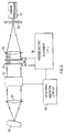
- the prior art slit-type imaging spectrometer as illustrated in Figure 1 comprises a collection optical system, such as a telescope as indicated at 2 , for collecting the incident light from the scene, schematically indicated at 4 and focusing the substantially parallel light of the scene onto a first focal plane occupied by a slit 6 to define the field of view.
- the light exiting from slit 6 is collimated in a collimator lens 8 and is passed through a transmission or reflection grating 10 to separate the various wavelengths.
- the output from grating 10 is focused by a focusing lens 12 onto a two-dimensional detector array 14 in a second focal plane.
- the output of detector array 14 is fed to a signal processor 16 .
- the movement of the system effects the scanning along one dimension.
- the scanning along the second dimension is effected by the slit 6 which is oriented perpendicularly to the direction of movement of the system.
- the slit 6 thus assures that each detector within the array 14 sees only the contribution of one pixel at a single wavelength at any time; this is necessary to separate the spectra of each pixel.
- the disadvantage of the prior art method illustrated in Figure 1 is that most of the pixels of one frame are not measured at any given time even though the telescope (2 or other collecting optics) actually collects energy from all of them simultaneously. As a result, the required frame time is significantly increased, and/or the signal-to-noise ratio (sensitivity) is substantially decreased with respect to a system, if it existed, which did not have the need for such a slit.
- Figure 2 is a block diagram illustrating the main components of an imaging spectrometer constructed in accordance with the present invention.
- the imaging spectrometer of Figure 2 includes: a collection optical system, generally designated 20 ; a one-dimensional or two-dimensional scanner, as indicated by block 22 ; an optical path difference (OPD) generator or interferometer, as indicated by block 24 ; a one-dimensional or two-dimensional detector array, as indicated by block 26 ; and a signal processor and display, as indicated by block 28 .
- a collection optical system generally designated 20
- a one-dimensional or two-dimensional scanner as indicated by block 22
- OPD optical path difference
- interferometer as indicated by block 24
- a one-dimensional or two-dimensional detector array as indicated by block 26
- a signal processor and display as indicated by block 28 .
- the radiation, such as light, to be analyzed can come from a wide variety of sources.
- the source may emit radiation spontaneously or reflect or transmit radiation from a lamp or other illuminated object.
- fluorescence or Raman spectral imaging measurements can be performed, in order to obtain different information about the about the object or objects in question in each case.
- a critical element in the novel system is the optical path difference generator or interferometer 24 , which outputs modulated light corresponding to a predetermined set of linear combinations of the spectral intensity of the light emitted from each pixel of the scene to be analyzed.
- the output of the interferometer is focused onto the detector array 26 .
- the interferometer used may be of either the moving or the non-moving type and the detector array may, independently of the type of interferometer, be one- or two-dimensional.
- the interferometer is of the moving type and the detector array is two-dimensional, no scanning is required, except for movement of the interferometer which is an OPD scan.
- OPD scanning in one dimension is required.
- the interferometer is of the non-moving type and the detector array is two-dimensional
- OPD scanning in one dimension is required.
- scanning in two dimensions is required, with one dimension relating to a spatial scan while the other relates to an OPD scan.
- Figure 3 illustrates one form of imaging spectrometer constructed in accordance with the present invention.
- This spectrometer is based on the use of a moving type interferometer in which the OPD is varied to modulate the light, namely, a Fabry-Perot interferometer 33 with scanned thickness.
- the imaging spectrometer illustrated in Figure 3 comprises a source or scene, generally designated 30 , to be analyzed to determine the spectral intensity of each pixel of the scene.
- the scene 30 may be a source of incoherent non-monochromatic radiation. It may be at a distance for remote-sensing applications, in which case the collection optical system, schematically indicated at 31 , would be a telescope; alternatively, the scene 30 may be close for microscopic analysis, in which case the collection optical system 31 would be a microscope.
- Optical system 31 provides an output to a one-dimensional mechanical scanner, e.g., a mirror scanner as indicated at 32 , to scan the scene.
- the output from scanner 32 is fed to a Fabry-Perot interferometer 33 having an etalon made of two plane, parallel reflectors spaced at a distance "d" from each other.
- the spacing distance "d" is variable by using a mechanical scanner, in this case a piezoelectric scanner 34 .
- the output from the Fabry-Perot interferometer 33 is fed through a refocusing optical system 35 onto a one-dimensional array of detectors 36 whose outputs are fed to a signal processor 37 . If a two-dimensional detector array is used, scanner 32 can be eliminated.
- Optical system 31 e.g., an afocal telescope or microscope, produces a substantially parallel beam (i.e., exactly parallel or having a very large F/No) at its output, because in this way every detector within the array 36 corresponds to a single optical phase difference through the etalon 34 of the Fabry-Perot interferometer 33 .
- the optical system 31 can be either refractive or reflective.
- the etalon 33 of the interferometer is at 90° to the optical axis of the system. It will be noted that no use is made of a field-of-view limiting aperture or slit.
- the array 36 is composed of a linear set of N detectors, whose signals can be monitored simultaneously and independently.
- the N lines and m columns correspond to the same matrix in object space.
- the Fabry-Perot thickness or optical phase difference is kept fixed for the time of integration of one line. Then the scanner performs a step vertically, and the Fabry-Perot thickness d is stepped in synchronization by one step, starting from zero, until N steps are performed. At this point the scanner continues scanning vertically, the thickness starts from zero again, and the steps are repeated until the complete field of view is scanned.
- this configuration does not correspond to a very high wavelength resolution but it is necessary in order not to lose a significant amount of radiation between the narrow peaks of the Airy function. This is a desirable situation, since in any case, because of the imaging, a high resolution may yield too much information to handle.
- d is the range
- the steps of thickness are of the order of 1 ⁇ .
- ⁇ 0.008 ⁇
- the significant features in the system illustrated in Figure 3 include: i) the special matching of the interferometer thickness range and finesse, with the detector array size and number of detectors and the spectral resolution; and ii) the synchronization between the thickness scanning and the spatial scanning, to obtain the spectral and the spatial information simultaneously in the time one frame is built.
- a spectrum may be measured for every pixel of a standard video frame. This is of the order of 100 resolution points per pixel, with a typical matrix of 500 x 500 pixels per frame.
- the invention may also be implemented by using a non-moving type interferometer, in which case the OPD varies with the angle of incidence of the incoming radiation.
- Figure 4 illustrates the invention implemented by using the latter type interferometer, namely, by using a Michelson type interferometer.
- the interferometer illustrated in Figure 4 includes a beamsplitter 40 receiving the beam from the optical collection system and scanner ( 31 and 32 , respectively, Figure 3), and splitting the beam into two paths.
- Scanner 32 may be one-dimensional or two-dimensional, depending on whether detector array 36 is two-dimensional or one-dimensional, respectively.
- One path includes a compensator 41 and a retroreflector 42 while the second path includes a compensator 43 and a retroreflector 44 .
- the two compensators, 41 and 43 are identical blocks of the same material and of the same thickness, and are positioned antisymmetrically in the two arms so that only beams which are parallel to the optical axis are compensated.
- the two retroreflectors, 42 and 44 are positioned at equal distances from the beamsplitter 40 .
- the beamsplitter 40 has a half-reflecting coating only on a portion of its surface on each side so that the translation of the beam through the corner cube is exploited to obtain a completely compensated system for rays parallel to the optical axis.
- the beam which is parallel to the optical axis of the system is compensated between the two arms of the interferometer, whereas the beams in directions which are off the optical axis of the system undergo OPD's (optical path differences) between the two arms which vary linearly with the incident angle.
- OPD's optical path differences
- each element of the array will receive light which underwent different OPD's between the two arms.
- compensator 41 is removed and beamsplitter 40 is half-reflecting on the whole surface on the side of the incoming beam, then one obtains another viable configuration with a compensated optical axis.
- the spectral range of the radiation reaching the detector is limited to, ⁇ 1 ⁇ ⁇ ⁇ ⁇ 2 by using a suitable filter, or because of the transmission properties of the optics.
- the interferogram must be sampled with OPD steps which are no larger than ⁇ 1 /2.
- OPD steps which are no larger than ⁇ 1 /2.
- this is also the difference in OPD subtended by two adjacent detectors. Since one period is an OPD change of one wavelength, the maximum difference in OPD seen by two adjacent detector elements must be, ⁇ 1 /2
- the uniqueness of the system illustrated in Figure 4 is represented by: i) the OPD is a linear function of the angle of incidence of the incoming radiation on the interferometer, so that different detectors of the array see it at different OPD's. This fact, combined with the spatial scanning and proper bookkeeping, allows the interferogram or Fourier transform of the spectrum of each pixel to be measured simultaneously with the image information.
- the scanning in the case of a non-moving interferometer can be two-dimensional or one-dimensional, depending on whether the detector array is one-dimensional or two-dimensional, respectively.
- Figure 5 illustrates an imaging spectrometer including a Michelson interferometer but of the moving type, similar to that of Figure 3, namely, wherein the OPD varies with moving an element of the interferometer.
- the light from source 50 is collected by the optical collection system 51 and is collimated onto a scanning mirror 52 before being passed through the beamsplitter 53 which splits the beam into the two arms.
- One arm includes a compensator 54 and a mirror 55
- the second arm includes merely a mirror 56 .
- the light from the two mirrors is passed via beamsplitter 53 and a focusing lens 57 onto an array of detectors 58 .
- the direction of the scanning is perpendicular to the direction of the linear array and the scanning mirror 52 scans the scene in one dimension.
- Scanner 52 is not needed if the detector array is two-dimensional.
- Scanner 59a controls the distance between mirror 56 and beamsplitter 53 .
- the compensator 54 ensures that the central beam has an OPD equal to zero.
- Many different scanning configurations and sequences may be possible, including ones in which the synchronization is not needed while the image scanner is or is not needed, depending on the whether the detector array is one-dimensional or two-dimensional.
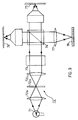
- FIG 6 illustrates an imaging spectrometer constructed in accordance with the present invention but utilizing another type interferometer, namely, a modified Sagnac, of the non-moving type in that the OPD varies with the angle of incidence of the incoming radiation.
- a beam entering the interferometer at a small angle to the optical axis undergoes an OPD which varies linearly with this angle.
- the modified Sagnac interferometer illustrated in the spectrometer of Figure 6 is that described in D.E, Hecht, Optics, Addison-Wesley Publishing Company, p. 359 (1987).
- this interferometer all the radiation from source 60 in all the pixels, after being collimated by the optical collection system 61 , is scanned by a mechanical scanner 62 .
- the light is then passed through a beamsplitter 63 to a first reflector 64 and then to a second reflector 65 , which reflects the light back through the beamsplitter 63 and then through a focusing lens 66 to an array of detectors 67 .
- This beam interferes with the beam which is reflected by 63 , then by 65 , and finally by reflector 64 .
- With a one-dimensional array a two-dimensional scan is required while with a two-dimensional detector array, only a one-dimensional scan is required.
- every pixel has been measured through all the OPD's by different detectors at different times, and therefore the spectrum can be reconstructed by Fourier transformation.
- a beam parallel to the optical axis is compensated, and a beam at an angle ( ⁇ ) to the optical axis undergoes an OPD which is a function of the thickness of the beamsplitter 63 , its index of refraction, and the angle ⁇ .
- the OPD is proportional to ⁇ for small angles.
- the beam including the central beam on the optical axis and other parallel beams at non-zero angles with respect to it within the instrument's field of view, enters the interferometer and is split into two coherent beams by the beamsplitter 63 .
- the two split beams are rejoined after being folded by mirrors, 64 and 65 , and create interference patterns on the detector array 67 where they are focused by focusing lens 66 .
- Figure 6A can be used to illustrate this concept.
- a laser or UV lamp 68 is used to illuminate source 60 .
- the induced fluorescence spectrum emitted by source 60 is then measured by the spectral imager.
- a notch filter 69 is placed in front of detector array 67 , or in any other suitable location.
- notch filter 69 The function of notch filter 69 is to block the scattered or reflected radiation of the laser or lamp itself. The blocking is necessary to prevent the flooding of detector array 67 with undesired signals.
- the function of notch filter 69 can alternatively be fulfilled by any suitable type of filter which is capable of cutting off the reflected or scattered light from the lamp. In the case of a UV lamp, the lamp itself typically includes a cut-off filter which limits the spectral range of the light incident upon the sample. In addition, since the fluorescent light is usually weak cooled or intensified detector arrays may be used to increase the signal to noise ratio of the measurement.
- the situation is as with fluorescence except that a laser 68 is used.
- the radiation source may be placed as in Figure 6A for reflection analysis. In the case of transmission analysis, the radiation source would be placed behind source 60 , i.e., to the left of source 60 in Figure 6A.
- the scanning between the scene and the interferometer fringes can be performed either by using a scanner external to the interferometer (moving scene) or by rotating the interferometer itself (moving fringes).
- a scanner external to the interferometer moving scene
- moving fringes rotating the interferometer itself
- Equation (30) it follows from Equation (30) that by scanning both positive and negative angles with respect to the central position, one can get a double-sided interferogram for every pixel, which helps eliminate phase errors giving more accurate results in the Fourier Transform calculation.
- the scanning amplitude determines the maximum OPD reached, which is related to the spectral resolution of the measurement.
- the size of the angular steps determines the OPD step which is, in turn, dictated by the shortest wavelength to which the system is sensitive. In fact, according to the Nyquist theorem, this OPD step must be smaller than half the shortest wavelength to which the system is sensitive.
- Another parameter which should be taken into account is the finite size of a detector element in the matrix.
- the element Through the focusing optics, the element subtends a finite OPD in the Sagnac interferometer which has the effect of convolving the interferogram with a rectangular function. This brings about, as a consequence, a reduction of system sensitivity at short wavelengths, which drops to zero for wavelengths equal to or below the OPD subtended by the element. For this reason, one must ensure that the Modulation Transfer Function (MTF) condition is satisfied, i.e., that the OPD subtended by a detector element in the interferometer must be smaller than the shortest wavelength at which the instrument is sensitive.
- MTF Modulation Transfer Function
- Figure 9 illustrates an additional imaging spectrometer including a Michelson interferometer of the moving type, similar to that illustrated in Figure 5, but constructed so that the light is focused on the reflectors through microscope objectives.
- the spectrometer illustrated in Figure 9 includes a light source 71 and a microscope optical system 72 including a condenser lens 72a , for focusing on the object 72b .
- Optical system 72 further includes a collimator lens 72c for directing the light through a scanner 73 , through a beamsplitter 74 to the two reflectors, 75 and 76 , and then through a focusing lens 77 onto a detector array 78 .
- the detector array 78 in configuration of Figure 9, as well as in the previously-described configurations, may be a CCD (charge coupled device).
- the scanner 73 scans the field of view in one dimension if the detector array is one-dimensional. It is not needed at all if the detector array is two-dimensional. Reflector 75 and the microscope system move together along the optical axis to provide scanning of the OPD in synchronization with the scanner 73 (if present), as described above with respect to Figure 5.
- the OPD for every pixel can be scanned in two ways:
- the detector is a linear array
- a one-dimensional optical scan of the scene must be added to the interferometer scan, if the entire scene is to be analyzed.
- no additional optical scan is needed, except for the interferometer, but there are many working configurations depending on the dimensionality of the detector array and the type of interferometer used.
- method (1) the spectral resolution is limited by the number of detectors and by the total OPD range allowed by the geometry of the setup.
- method (2) depending on the type of interferometer used, it is possible to reach very large OPD's. Since the spectral resolution attainable is higher when a higher maximum OPD is scanned, it is clear that the second method is more suitable when high resolution is required.
- inventions of Figures 10-15 are based on the second method, namely, the one wherein the scene is fixed and the OPD scanning is effected by a movable element of the interferometer or the interferometer itself, and on a third method, which is based on a fixed interferometer with an additional compensating scanner mirror (single or double-sided), in order to keep the scene stationary, and scan the interference fringes across the scene.
- the light is passed through a moving type interferometer, in which the OPD is varied to modulate the light by moving an element of the interferometer or a compensating mirror, or the interferometer itself, such that at each instant, each detector sees a linear combination (Fourier transform) of the spectral content of the light emitted from each pixel, and it looks at a different pixel of the scene, and that when the scanner completes one scan, the complete scene will have been scanned at all relevant linear combinations of the spectral content.
- a moving type interferometer in which the OPD is varied to modulate the light by moving an element of the interferometer or a compensating mirror, or the interferometer itself, such that at each instant, each detector sees a linear combination (Fourier transform) of the spectral content of the light emitted from each pixel, and it looks at a different pixel of the scene, and that when the scanner completes one scan, the complete scene will have been scanned at all relevant linear combinations of the spectral content.
- Figures 10-15 illustrate further implementations of the second method and two implementations of the third method, i.e. wherein the scene is kept fixed and the interference fringes scan the scene.
- Figure 10 illustrates an imaging spectrometer of a type similar to the modified Sagnac interferometer illustrated in Figure 6, except that it is based on method (2) described above, namely, effecting the scanning by a movable element of the interferometer, rather than method (1) above, wherein scanning is effected by scanning the image.
- the imaging spectrometer illustrated in Figure 10 is similar to that illustrated in Figure 6, in that it includes an optical image source 110 in which all the spectral information in all its pixels, after being collimated by the optical collection system 111 , is scanned by a mechanical scanner 112 .
- This scanner is needed only if the detector array is linear. If it is two-dimensional, it is not needed.
- the light is then passed through a beamsplitter 113 to a first reflector 114 , and then to a second reflector 115 , which reflects the light back through the beamsplitter 113 and then through a focusing lens 116 to a detector array 117 .
- the beamsplitter 113 is rotated about an axis perpendicular to the optical path (and perpendicular to the paper) to effect the scanning.
- this rotation of the beamsplitter changes the OPD through which a collimated beam from a pixel reaches a specific detector: without changing the detector on which it is focused. It is thus clear that a scan of the beamsplitter angle with respect to the optical axis causes every pixel to be scanned through an OPD range.
- Figure 11 illustrates an imaging spectrometer similar to that of Figure 10 above or to Figure 6, except that it includes an optical plate 128 of a light-transmitting material, which increases the maximum OPD, and thereby increases the spectral resolution of the apparatus.
- the optical plate 128 is located between the beamsplitter 123 and the second reflector 125 , which reflects the light from the first reflector 124 back through the beamsplitter 123 and then through a focusing lens 126 to the detector array 127 .
- Figure 12 illustrates an imaging spectrometer very similar to that of Figure 2, except for a slightly different orientation of the first reflector 134 , the second reflector 135 , the optical plate 138 , the beamsplitter 133 , and the detector array 137 including its focusing lens 136 .
- Figure 13 illustrates an imaging spectrometer including an interferometer of the Michelson type, similar to Figure 5.
- a two-dimensional detector array 147 is used, and therefore, a one-dimensional scanning is sufficient, rather than a two-dimensional scanning as in the apparatus illustrated in Figure 5.
- the scanning is effected by mirror 146 controlled by scanner 149a , to change the distance between the mirror and the beamsplitter 143 , and thereby to vary the OPD.
- the system illustrated in Figure 13 obviates the need for the synchronization circuit 59 and scanning mirror 52 included in Figure 5.
- Figures 14 and 15 illustrate two further embodiments of the invention which provide advantages over the embodiment illustrated in Figure 10.
- the distance between fringes varies as a function of beamsplitter angle. This makes the transformation algorithm inconvenient and difficult to use.
- the fringes scan the image without changing the distance between them. In this way, a constant fringe distance is attained, with the possibility of reaching higher spectral resolution and easier algorithm.
- Figure 14 illustrates an apparatus based on the Sagnac interferometer including a scanning mirror 152 and a beamsplitter 153 .
- the scanning mirror 152 rather than the beamsplitter 153 , is rotated about an axis perpendicular to the optical path (and perpendicular to the plane of the paper) to effect the scanning.
- mirror 152 is a double-sided mirror.
- Figure 15 illustrates a similar arrangement as in Figure 14, except that the scanning mirror 162 is single-sided and is rotated, as mirror 152 in Figure 14, to effect the OPD scanning via the beamsplitter 163 .
- imaging spectrometers constructed in accordance with the present invention do not merely measure the intensity of light coming from every pixel in the field of view, but also measure the spectrum of each pixel in a predefined wavelength range. They also better utilize all the radiation emitted by each pixel in the field of view at any given time, and therefore permit a significant decrease in the frame time and/or a significant increase in the sensitivity of the spectrometer.
- imaging spectrometers may include other types of interferometers and optical collection and focusing systems, and may be used in a wide variety of applications, including medical diagnostic applications, remote sensing for geological and agricultural investigations, and the like.
Landscapes
- Physics & Mathematics (AREA)
- Spectroscopy & Molecular Physics (AREA)
- General Physics & Mathematics (AREA)
- Health & Medical Sciences (AREA)
- Chemical & Material Sciences (AREA)
- Life Sciences & Earth Sciences (AREA)
- Engineering & Computer Science (AREA)
- Analytical Chemistry (AREA)
- General Health & Medical Sciences (AREA)
- Immunology (AREA)
- Proteomics, Peptides & Aminoacids (AREA)
- Organic Chemistry (AREA)
- Biochemistry (AREA)
- Pathology (AREA)
- Genetics & Genomics (AREA)
- Wood Science & Technology (AREA)
- Multimedia (AREA)
- Zoology (AREA)
- Nuclear Medicine, Radiotherapy & Molecular Imaging (AREA)
- Molecular Biology (AREA)
- Theoretical Computer Science (AREA)
- Microbiology (AREA)
- Biotechnology (AREA)
- Bioinformatics & Cheminformatics (AREA)
- General Engineering & Computer Science (AREA)
- Biophysics (AREA)
- Chemical Kinetics & Catalysis (AREA)
- Optics & Photonics (AREA)
- Biomedical Technology (AREA)
- Spectrometry And Color Measurement (AREA)
Priority Applications (11)
| Application Number | Priority Date | Filing Date | Title |
|---|---|---|---|
| EP93203737A EP0767361B1 (de) | 1993-07-22 | 1993-07-22 | Verfahren und Vorrichtung zur Spektralen Bilderfassung |
| DE69327909T DE69327909T2 (de) | 1993-07-22 | 1993-07-22 | Verfahren und Vorrichtung zur Spektralen Bilderfassung |
| DE69332492T DE69332492T2 (de) | 1993-07-22 | 1993-07-22 | Verfahren und Vorrichtungen zur spektralen Abbildung mittels Fabry-Perot-Interferometern |
| EP99111904A EP0957346A3 (de) | 1993-07-22 | 1993-07-22 | Verfahren und Vorrichtungen zur spektralen Abbildung mittels eines Interferometers mit gegenseitiger Überlagerung einer endlichen Zahl von kohärenten Strahlen |
| ES93203737T ES2144441T3 (es) | 1993-07-22 | 1993-07-22 | Procedimiento y aparato para el analisis espectral de imagenes. |
| ES99111903T ES2188065T3 (es) | 1993-07-22 | 1993-07-22 | Metodos y aparatos para la formacion de imagenes espectrales utilizando interferometros del tipo fabry-perot. |
| AT93203737T ATE189927T1 (de) | 1993-07-22 | 1993-07-22 | Verfahren und vorrichtung zur spektralen bilderfassung |
| EP99111903A EP0957345B1 (de) | 1993-07-22 | 1993-07-22 | Verfahren und Vorrichtungen zur spektralen Abbildung mittels Fabry-Perot-Interferometern |
| DK93203737T DK0767361T3 (da) | 1993-07-22 | 1993-07-22 | Fremgangsmåde og apparat til spektral billeddannelse |
| US08/392,019 US5539517A (en) | 1993-07-22 | 1995-02-21 | Method for simultaneously measuring the spectral intensity as a function of wavelength of all the pixels of a two dimensional scene |
| GR20000401166T GR3033470T3 (en) | 1993-07-22 | 2000-05-22 | Method and apparatus for spectral analysis |
Applications Claiming Priority (2)
| Application Number | Priority Date | Filing Date | Title |
|---|---|---|---|
| EP93203737A EP0767361B1 (de) | 1993-07-22 | 1993-07-22 | Verfahren und Vorrichtung zur Spektralen Bilderfassung |
| US08/392,019 US5539517A (en) | 1993-07-22 | 1995-02-21 | Method for simultaneously measuring the spectral intensity as a function of wavelength of all the pixels of a two dimensional scene |
Related Child Applications (2)
| Application Number | Title | Priority Date | Filing Date |
|---|---|---|---|
| EP99111904A Division EP0957346A3 (de) | 1993-07-22 | 1993-07-22 | Verfahren und Vorrichtungen zur spektralen Abbildung mittels eines Interferometers mit gegenseitiger Überlagerung einer endlichen Zahl von kohärenten Strahlen |
| EP99111903A Division EP0957345B1 (de) | 1993-07-22 | 1993-07-22 | Verfahren und Vorrichtungen zur spektralen Abbildung mittels Fabry-Perot-Interferometern |
Publications (3)
| Publication Number | Publication Date |
|---|---|
| EP0767361A2 true EP0767361A2 (de) | 1997-04-09 |
| EP0767361A3 EP0767361A3 (de) | 1997-08-13 |
| EP0767361B1 EP0767361B1 (de) | 2000-02-23 |
Family
ID=26134125
Family Applications (1)
| Application Number | Title | Priority Date | Filing Date |
|---|---|---|---|
| EP93203737A Expired - Lifetime EP0767361B1 (de) | 1993-07-22 | 1993-07-22 | Verfahren und Vorrichtung zur Spektralen Bilderfassung |
Country Status (3)
| Country | Link |
|---|---|
| US (1) | US5539517A (de) |
| EP (1) | EP0767361B1 (de) |
| GR (1) | GR3033470T3 (de) |
Cited By (7)
| Publication number | Priority date | Publication date | Assignee | Title |
|---|---|---|---|---|
| EP0832417A1 (de) * | 1995-12-20 | 1998-04-01 | Spectral Diagnostic Ltd | Verfahren zur gleichzeitigen detektion von mehreren fluorophoren zur in situ hybridisierung und anfärbung von chromosomen |
| WO2000062026A1 (de) * | 1999-04-09 | 2000-10-19 | Campus Technologies Ag | Vorrichtung und verfahren zur optischen spektroskopie |
| WO2001023849A1 (en) * | 1999-09-30 | 2001-04-05 | Bae Systems Avionics Limited | An imaging system |
| WO2007084945A1 (en) * | 2006-01-19 | 2007-07-26 | The General Hospital Corporation | Systems and methods for performing rapid fluorescense lifetime, excitation and emission spectral measurements |
| WO2010076520A2 (fr) | 2009-01-05 | 2010-07-08 | Centre National D'etudes Spatiales | Engin aeronautique |
| EP2264416A1 (de) * | 2009-06-19 | 2010-12-22 | Thales | System und Verfahren zur statischen Interferenzmessung |
| JP2014514580A (ja) * | 2011-05-06 | 2014-06-19 | ビオメリュー | バイオ画像化方法及びシステム |
Families Citing this family (154)
| Publication number | Priority date | Publication date | Assignee | Title |
|---|---|---|---|---|
| US5817462A (en) * | 1995-02-21 | 1998-10-06 | Applied Spectral Imaging | Method for simultaneous detection of multiple fluorophores for in situ hybridization and multicolor chromosome painting and banding |
| US5784162A (en) * | 1993-08-18 | 1998-07-21 | Applied Spectral Imaging Ltd. | Spectral bio-imaging methods for biological research, medical diagnostics and therapy |
| US6198532B1 (en) * | 1991-02-22 | 2001-03-06 | Applied Spectral Imaging Ltd. | Spectral bio-imaging of the eye |
| US5991028A (en) * | 1991-02-22 | 1999-11-23 | Applied Spectral Imaging Ltd. | Spectral bio-imaging methods for cell classification |
| USRE36529E (en) * | 1992-03-06 | 2000-01-25 | The United States Of America As Represented By The Department Of Health And Human Services | Spectroscopic imaging device employing imaging quality spectral filters |
| US6075599A (en) * | 1993-08-18 | 2000-06-13 | Applied Spectral Imaging Ltd. | Optical device with entrance and exit paths that are stationary under device rotation |
| US6690817B1 (en) * | 1993-08-18 | 2004-02-10 | Applied Spectral Imaging Ltd. | Spectral bio-imaging data for cell classification using internal reference |
| US5995645A (en) * | 1993-08-18 | 1999-11-30 | Applied Spectral Imaging Ltd. | Method of cancer cell detection |
| US5863504A (en) * | 1995-03-16 | 1999-01-26 | Bio-Rad Laboratories, Inc. | Fluorescence imaging instrument utilizing fish |
| US6007994A (en) | 1995-12-22 | 1999-12-28 | Yale University | Multiparametric fluorescence in situ hybridization |
| US5792610A (en) * | 1996-05-01 | 1998-08-11 | Biorad Laboratories, Inc. | Method for conducting multiparametric fluorescence in situ hybridization |
| IL119520A0 (en) * | 1996-10-30 | 1997-01-10 | Applied Spectral Imaging Ltd | Method for interferometer based spectral imaging of moving objects |
| US6135965A (en) * | 1996-12-02 | 2000-10-24 | Board Of Regents, The University Of Texas System | Spectroscopic detection of cervical pre-cancer using radial basis function networks |
| US5891619A (en) * | 1997-01-14 | 1999-04-06 | Inphocyte, Inc. | System and method for mapping the distribution of normal and abnormal cells in sections of tissue |
| AUPO512697A0 (en) * | 1997-02-14 | 1997-04-11 | Indx Pty Ltd | Improvements in a system for writing gratings |
| US6937885B1 (en) | 1997-10-30 | 2005-08-30 | Hypermed, Inc. | Multispectral/hyperspectral medical instrument |
| US6051835A (en) * | 1998-01-07 | 2000-04-18 | Bio-Rad Laboratories, Inc. | Spectral imaging apparatus and methodology |
| US6271957B1 (en) * | 1998-05-29 | 2001-08-07 | Affymetrix, Inc. | Methods involving direct write optical lithography |
| US6657758B1 (en) | 1998-06-04 | 2003-12-02 | Board Of Regents, The University Of Texas System | Variable spectrum generator system |
| US6160618A (en) * | 1998-06-19 | 2000-12-12 | Board Of Regents, The University Of Texas System | Hyperspectral slide reader |
| US6276798B1 (en) * | 1998-09-29 | 2001-08-21 | Applied Spectral Imaging, Ltd. | Spectral bio-imaging of the eye |
| US6337472B1 (en) | 1998-10-19 | 2002-01-08 | The University Of Texas System Board Of Regents | Light imaging microscope having spatially resolved images |
| US6637882B1 (en) | 1998-11-24 | 2003-10-28 | Welch Allyn, Inc. | Eye viewing device for retinal viewing through undilated pupil |
| US20040111219A1 (en) * | 1999-02-22 | 2004-06-10 | Sandeep Gulati | Active interferometric signal analysis in software |
| EP1169722A1 (de) | 1999-03-18 | 2002-01-09 | Cambridge Research & Instrumentation, Inc. | Hochwirkames mehrfachsonden-bilderzeugungssystem |
| WO2000067635A1 (en) * | 1999-05-07 | 2000-11-16 | Applied Spectral Imaging Ltd. | Spectral bio-imaging of the eye |
| WO2001002799A1 (en) | 1999-07-02 | 2001-01-11 | Cambridge Research & Instrumentation Inc. | Birefringement interferometer |
| US6734962B2 (en) * | 2000-10-13 | 2004-05-11 | Chemimage Corporation | Near infrared chemical imaging microscope |
| WO2001009592A1 (en) * | 1999-07-30 | 2001-02-08 | California Institute Of Technology | System and method for monitoring cellular activity |
| EP1208367A4 (de) | 1999-08-06 | 2007-03-07 | Cambridge Res & Instrmnt Inc | Vorrichtung zur spektralen abbildung |
| US6750964B2 (en) * | 1999-08-06 | 2004-06-15 | Cambridge Research And Instrumentation, Inc. | Spectral imaging methods and systems |
| US7554586B1 (en) | 1999-10-20 | 2009-06-30 | Rochester Institute Of Technology | System and method for scene image acquisition and spectral estimation using a wide-band multi-channel image capture |
| US6747737B2 (en) | 2000-06-29 | 2004-06-08 | Carl Zeiss Jena Gmbh | Method for optical detection of an illuminated specimen in a plurality of detection channels |
| US6958811B2 (en) | 2000-06-29 | 2005-10-25 | Carl Zeiss Jena Gmbh | Method for the detection of dyes in fluorescence microscopy |
| US6858852B2 (en) | 2000-08-08 | 2005-02-22 | Carl Zeiss Jena Gmbh | Method and apparatus for rapid change of fluorescence bands in the detection of dyes in fluorescence microscopy |
| US6947133B2 (en) * | 2000-08-08 | 2005-09-20 | Carl Zeiss Jena Gmbh | Method for increasing the spectral and spatial resolution of detectors |
| US6670087B2 (en) * | 2000-11-07 | 2003-12-30 | Canon Kabushiki Kaisha | Toner, image-forming apparatus, process cartridge and image forming method |
| JP3723082B2 (ja) * | 2001-01-31 | 2005-12-07 | 株式会社ニデック | 眼科装置 |
| AU2002324422A1 (en) * | 2001-02-21 | 2002-12-23 | Amnis Corporation | Method and apparatus for labeling and analyzing cellular components |
| US6771400B2 (en) * | 2001-03-16 | 2004-08-03 | Larry Kleiman | Hyperspectral system for capturing graphical images |
| US7596404B2 (en) * | 2001-06-28 | 2009-09-29 | Chemimage Corporation | Method of chemical imaging to determine tissue margins during surgery |
| US8078268B2 (en) | 2001-06-28 | 2011-12-13 | Chemimage Corporation | System and method of chemical imaging using pulsed laser excitation and time-gated detection to determine tissue margins during surgery |
| US6930773B2 (en) * | 2001-08-23 | 2005-08-16 | Cambridge Research And Instrumentation, Inc. | Spectral imaging |
| US20050032060A1 (en) * | 2001-08-31 | 2005-02-10 | Shishir Shah | Arrays comprising pre-labeled biological molecules and methods for making and using these arrays |
| US7439346B2 (en) * | 2001-10-12 | 2008-10-21 | Perkinelmer Las Inc. | Nucleic acids arrays and methods of use therefor |
| JP2005519634A (ja) | 2001-10-12 | 2005-07-07 | スペクトラル ジェノミクス、インク. | 核酸組成物及びアレイ及びそれらを用いる方法 |
| US8395769B2 (en) * | 2002-01-10 | 2013-03-12 | Chemimage Corporation | Method for analysis of pathogenic microorganisms using raman spectroscopic techniques |
| JP2005515423A (ja) * | 2002-01-10 | 2005-05-26 | ケムルメイジ コーポレーション | 病原性微生物の検出方法 |
| US6916621B2 (en) * | 2002-03-27 | 2005-07-12 | Spectral Genomics, Inc. | Methods for array-based comparitive binding assays |
| IL149016A0 (en) | 2002-04-07 | 2004-03-28 | Green Vision Systems Ltd Green | Method and device for real time high speed high resolution spectral imaging |
| US6825930B2 (en) * | 2002-06-04 | 2004-11-30 | Cambridge Research And Instrumentation, Inc. | Multispectral imaging system |
| US6992775B2 (en) * | 2002-08-29 | 2006-01-31 | Kestrel Corporation | Hyperspectral retinal imager |
| US7139081B2 (en) | 2002-09-09 | 2006-11-21 | Zygo Corporation | Interferometry method for ellipsometry, reflectometry, and scatterometry measurements, including characterization of thin film structures |
| US7869057B2 (en) | 2002-09-09 | 2011-01-11 | Zygo Corporation | Multiple-angle multiple-wavelength interferometer using high-NA imaging and spectral analysis |
| US20050287661A1 (en) * | 2002-10-08 | 2005-12-29 | James Landers | Methods and systems for multiplexing ir-mediated heating on a microchip |
| US7298885B2 (en) * | 2002-11-27 | 2007-11-20 | 3M Innovative Properties Company | Biological growth plate scanner with automated image processing profile selection |
| US20040102903A1 (en) * | 2002-11-27 | 2004-05-27 | Graessle Josef A. | Biological growth plate scanner |
| US7319031B2 (en) * | 2002-11-27 | 2008-01-15 | 3M Innovative Properties Company | Mounting platform for biological growth plate scanner |
| US20040101954A1 (en) * | 2002-11-27 | 2004-05-27 | Graessle Josef A. | Back side plate illumination for biological growth plate scanner |
| US7351574B2 (en) * | 2002-11-27 | 2008-04-01 | 3M Innovative Properties Company | Loading and ejection systems for biological growth plate scanner |
| US7583419B2 (en) * | 2003-01-09 | 2009-09-01 | Larry Kleiman | System for capturing graphical images using hyperspectral illumination |
| US6989901B2 (en) * | 2003-07-02 | 2006-01-24 | Inlight Solutions, Inc. | Interferometer |
| EP1588135B1 (de) * | 2003-01-29 | 2006-09-13 | Max-Planck-Gesellschaft zur Förderung der Wissenschaften e.V. | Anordnung und verfahren zur spektral auflösenden erfassung einer probe |
| US7324214B2 (en) | 2003-03-06 | 2008-01-29 | Zygo Corporation | Interferometer and method for measuring characteristics of optically unresolved surface features |
| US7538869B2 (en) * | 2004-06-30 | 2009-05-26 | Chemimage Corporation | Multipoint method for identifying hazardous agents |
| US7050215B1 (en) | 2003-08-01 | 2006-05-23 | Ball Aerospace & Technologies Corp. | Method and apparatus for providing a gas correlation filter for remote sensing of atmospheric trace gases |
| US7030991B1 (en) | 2003-08-01 | 2006-04-18 | Ball Aerospace & Technologies Corp. | Field condensing imaging system for remote sensing of atmospheric trace gases |
| US7496225B2 (en) * | 2003-09-04 | 2009-02-24 | 3M Innovative Properties Company | Biological growth plate scanner with automated intake |
| US7298886B2 (en) * | 2003-09-05 | 2007-11-20 | 3M Innovative Properties Company | Counting biological agents on biological growth plates |
| WO2005029192A2 (en) | 2003-09-15 | 2005-03-31 | Zygo Corporation | Surface triangulation and profiling through a thin film coating |
| GB0322043D0 (en) * | 2003-09-20 | 2003-10-22 | Qinetiq Ltd | Apparatus for,and method of,classifying objects in waste stream |
| US7321791B2 (en) * | 2003-09-23 | 2008-01-22 | Cambridge Research And Instrumentation, Inc. | Spectral imaging of deep tissue |
| US8634607B2 (en) * | 2003-09-23 | 2014-01-21 | Cambridge Research & Instrumentation, Inc. | Spectral imaging of biological samples |
| JP2007515947A (ja) * | 2003-10-30 | 2007-06-21 | タフツ−ニュー イングランド メディカル センター | 羊水中の無細胞胎児dnaを使用する出生前診断 |
| US7230697B2 (en) * | 2004-01-21 | 2007-06-12 | Roper Industries, Inc. | Method and apparatus for multi-mode spectral imaging |
| US7315371B2 (en) * | 2004-01-23 | 2008-01-01 | P&P Optica Inc. | Multi-channel spectrum analyzer |
| CA2567627C (en) * | 2004-05-20 | 2014-09-30 | Quest Diagnostics Investments Incorporated | Single label comparative hybridization |
| US7564546B2 (en) * | 2004-06-30 | 2009-07-21 | Chemimage Corporation | Dynamic imaging of biological cells and other subjects |
| US7135682B1 (en) * | 2004-08-05 | 2006-11-14 | University Of Hawai'i | Uncooled long-wave infrared hyperspectral imaging |
| EP1792263A2 (de) * | 2004-09-02 | 2007-06-06 | Vialogy Corporation | Erkennung von interessensereignissen unter verwendung von quantenresonanzinterferometrie |
| US8548570B2 (en) * | 2004-11-29 | 2013-10-01 | Hypermed Imaging, Inc. | Hyperspectral imaging of angiogenesis |
| US8224425B2 (en) * | 2005-04-04 | 2012-07-17 | Hypermed Imaging, Inc. | Hyperspectral imaging in diabetes and peripheral vascular disease |
| CA3031088A1 (en) | 2004-11-29 | 2006-06-01 | Hypermed Imaging, Inc. | Medical hyperspectral imaging for evaluation of tissue and tumor |
| US7616323B2 (en) | 2005-01-20 | 2009-11-10 | Zygo Corporation | Interferometer with multiple modes of operation for determining characteristics of an object surface |
| EP2237189B1 (de) | 2005-01-27 | 2018-08-01 | Cambridge Research & Instrumentation, Inc. | Klassifizierung von Bildmerkmalen |
| WO2006081353A2 (en) * | 2005-01-27 | 2006-08-03 | Quest Diagnostics Investments Incorporated | Rapid comparative genome hybridization |
| US7480033B2 (en) * | 2005-02-09 | 2009-01-20 | Chem Lmage Corporation | System and method for the deposition, detection and identification of threat agents using a fiber array spectral translator |
| WO2006107947A2 (en) | 2005-04-04 | 2006-10-12 | Hypermed, Inc. | Hyperspectral imaging in diabetes and peripheral vascular disease |
| US8971984B2 (en) * | 2005-04-04 | 2015-03-03 | Hypermed Imaging, Inc. | Hyperspectral technology for assessing and treating diabetic foot and tissue disease |
| US8253936B2 (en) | 2008-08-08 | 2012-08-28 | Chemimage Corporation | Raman characterization of transplant tissue |
| US20060292576A1 (en) * | 2005-06-23 | 2006-12-28 | Quest Diagnostics Investments Incorporated | Non-in situ hybridization method for detecting chromosomal abnormalities |
| US8547540B2 (en) | 2005-07-14 | 2013-10-01 | Chemimage Corporation | System and method for combined raman and LIBS detection with targeting |
| US8687177B2 (en) * | 2007-01-23 | 2014-04-01 | Chemimage Corporation | System and method for combined Raman and LIBS detection |
| US8582089B2 (en) * | 2006-06-09 | 2013-11-12 | Chemimage Corporation | System and method for combined raman, SWIR and LIBS detection |
| US7518728B2 (en) * | 2005-09-30 | 2009-04-14 | Intel Corporation | Method and instrument for collecting fourier transform (FT) Raman spectra for imaging applications |
| WO2007044786A2 (en) | 2005-10-11 | 2007-04-19 | Zygo Corporation | Interferometry method and system including spectral decomposition |
| WO2007120192A2 (en) | 2005-10-27 | 2007-10-25 | The President And Fellows Of Harvard College | Methods and compositions for labeling nucleic acids |
| US8076074B2 (en) | 2005-11-29 | 2011-12-13 | Quest Diagnostics Investments Incorporated | Balanced translocation in comparative hybridization |
| US8379197B2 (en) | 2006-01-05 | 2013-02-19 | Chemimage Corporation | Spectroscopic systems and methods for classifying and pharmaceutically treating cells |
| JP5558005B2 (ja) * | 2006-01-23 | 2014-07-23 | ザイゴ コーポレーション | 物体をモニタする干渉計システム |
| WO2007087315A2 (en) | 2006-01-23 | 2007-08-02 | Chemimage Corporation | Method and system for combined raman and libs detection |
| TWI428559B (zh) | 2006-07-21 | 2014-03-01 | Zygo Corp | 在低同調干涉下系統性效應之補償方法和系統 |
| US7538872B1 (en) * | 2006-08-02 | 2009-05-26 | Butler Eugene W | Diagnostic methods and apparatus for directed energy applications |
| JP2008043494A (ja) * | 2006-08-14 | 2008-02-28 | Olympus Corp | 蛍光内視鏡システム、蛍光観測装置、蛍光観測方法、蛍光情報処理装置、および蛍光情報処理方法 |
| WO2008039758A2 (en) | 2006-09-25 | 2008-04-03 | Cambridge Research & Instrumentation, Inc. | Sample imaging and classification |
| US7807359B2 (en) * | 2006-12-01 | 2010-10-05 | Quest Diagnostics Investments Incorporated | Methods of detecting TPMT mutations |
| KR101519932B1 (ko) | 2006-12-22 | 2015-05-13 | 지고 코포레이션 | 표면 특징물의 특성을 측정하기 위한 장치 및 방법 |
| US8553210B2 (en) | 2007-01-23 | 2013-10-08 | Chemimage Corporation | System and method for combined Raman and LIBS detection with targeting |
| US7889355B2 (en) | 2007-01-31 | 2011-02-15 | Zygo Corporation | Interferometry for lateral metrology |
| US7619746B2 (en) | 2007-07-19 | 2009-11-17 | Zygo Corporation | Generating model signals for interferometry |
| US7507539B2 (en) * | 2007-07-30 | 2009-03-24 | Quest Diagnostics Investments Incorporated | Substractive single label comparative hybridization |
| US8330087B2 (en) * | 2007-10-16 | 2012-12-11 | Cambridge Research & Instrumentation, Inc. | Spectral imaging system with dynamic optical correction |
| US7978337B2 (en) | 2007-11-13 | 2011-07-12 | Zygo Corporation | Interferometer utilizing polarization scanning |
| US8093063B2 (en) * | 2007-11-29 | 2012-01-10 | Quest Diagnostics Investments Incorporated | Assay for detecting genetic abnormalities in genomic nucleic acids |
| US8126677B2 (en) | 2007-12-14 | 2012-02-28 | Zygo Corporation | Analyzing surface structure using scanning interferometry |
| CN101226344B (zh) * | 2008-01-31 | 2010-06-02 | 上海微电子装备有限公司 | 测量光学系统参数的测量装置及其测量方法 |
| WO2009111301A1 (en) * | 2008-03-04 | 2009-09-11 | 3M Innovative Properties Company | Information management in automated processing of biological growth media |
| EP2265733A4 (de) * | 2008-03-04 | 2017-12-13 | 3M Innovative Properties Company | Verarbeitung biologischer wachstumsmedien auf der grundlage gemessener herstellungsmerkmale |
| US8109634B2 (en) * | 2008-03-05 | 2012-02-07 | Tamir Gil | Snapshot spectral imaging of the eye |
| US8807751B2 (en) | 2008-04-22 | 2014-08-19 | Annidis Health Systems Corp. | Retinal fundus surveillance method and apparatus |
| EP2278909B1 (de) * | 2008-04-22 | 2016-02-17 | Annidis Health Systems Corp. | Verfahren und gerät zur beobachtung des netzhauthintergrunds |
| WO2009137369A1 (en) * | 2008-05-03 | 2009-11-12 | Tufts Medical Center, Inc. | Neonatal salivary genomics |
| US8199999B2 (en) | 2008-06-17 | 2012-06-12 | Cambridge Research & Instrumentation, Inc. | Image classifier training |
| US8644580B2 (en) * | 2008-08-07 | 2014-02-04 | Cambridge Research & Instrumentation, Inc. | Detection of RNA in tissue samples |
| US8416405B2 (en) * | 2008-08-08 | 2013-04-09 | Chemimage Corporation | Raman chemical imaging of implantable drug delivery devices |
| US8280134B2 (en) * | 2008-09-22 | 2012-10-02 | Cambridge Research & Instrumentation, Inc. | Multi-spectral imaging including at least one common stain |
| US8120781B2 (en) | 2008-11-26 | 2012-02-21 | Zygo Corporation | Interferometric systems and methods featuring spectral analysis of unevenly sampled data |
| US8039794B2 (en) * | 2008-12-16 | 2011-10-18 | Quest Diagnostics Investments Incorporated | Mass spectrometry assay for thiopurine-S-methyl transferase activity and products generated thereby |
| US9002077B2 (en) * | 2009-08-10 | 2015-04-07 | Cambridge Research & Instrumentation, Inc. | Visualization of stained samples |
| WO2011027315A1 (en) | 2009-09-04 | 2011-03-10 | Moshe Danny S | Grading of agricultural products via hyper spectral imaging and analysis |
| EP2480684A1 (de) * | 2009-09-25 | 2012-08-01 | Signature Genomic Laboratories, Llc | Mehrfach (+/-)-strängige arrays und tests für den nachweis von chromosomalen anomalien im zusammenhang mit krebs und anderen erkrankungen |
| US9664563B2 (en) * | 2009-12-02 | 2017-05-30 | University Of Hawaii | Fabry-perot fourier transform spectrometer |
| WO2011097508A2 (en) * | 2010-02-04 | 2011-08-11 | University Of Southern California | Combined spectral and polarimetry imaging and diagnostics |
| US8462981B2 (en) | 2010-04-07 | 2013-06-11 | Cambridge Research & Instrumentation, Inc. | Spectral unmixing for visualization of samples |
| JP5832537B2 (ja) | 2010-08-05 | 2015-12-16 | ケンブリッジ・リサーチ・アンド・インストルメンテーション・インコーポレーテッド | 試料の強調視覚評価 |
| JP5384453B2 (ja) | 2010-09-09 | 2014-01-08 | シャープ株式会社 | 測定装置、測定システム、測定方法、制御プログラム、および、記録媒体 |
| US8563934B2 (en) * | 2010-09-10 | 2013-10-22 | Mississippi State University | Method and detection system for detection of aflatoxin in corn with fluorescence spectra |
| US8520074B2 (en) | 2010-12-14 | 2013-08-27 | Xerox Corporation | Determining a total number of people in an IR image obtained via an IR imaging system |
| US9019358B2 (en) | 2011-02-08 | 2015-04-28 | Xerox Corporation | Method for classifying a pixel of a hyperspectral image in a remote sensing application |
| CN102322956A (zh) * | 2011-05-20 | 2012-01-18 | 中国科学院上海光学精密机械研究所 | 转镜式傅里叶干涉成像光谱仪 |
| US9212381B2 (en) | 2011-11-10 | 2015-12-15 | President And Fellows Of Harvard College | Methods and compositions for labeling polypeptides |
| WO2013179279A2 (en) | 2012-05-28 | 2013-12-05 | Applied Spectral Imaging Ltd. | Method and device for analyzing biological sample |
| JP5576993B2 (ja) | 2012-05-30 | 2014-08-20 | パナソニック株式会社 | 画像計測装置、画像計測方法及び画像計測システム |
| WO2014064701A1 (en) * | 2012-10-26 | 2014-05-01 | Applied Spectral Imaging Ltd. | Method and system for spectral imaging |
| WO2014190027A1 (en) | 2013-05-22 | 2014-11-27 | Massachusetts Institute Of Technology | Methods, systems, and apparatus for imaging spectroscopy |
| WO2017011752A1 (en) | 2015-07-15 | 2017-01-19 | Massachusetts Institute Of Technology | Systems, apparatus, and methods for spectral imaging |
| US11012643B2 (en) | 2015-12-15 | 2021-05-18 | Applied Spectral Imaging Ltd. | System and method for spectral imaging |
| CN105596011B (zh) * | 2016-02-25 | 2018-11-20 | 中山北京理工大学研究院 | 一种无创血糖检测装置 |
| CN108680979A (zh) * | 2018-06-21 | 2018-10-19 | 中国人民解放军63908部队 | 二维正弦光栅抗偏振敏感sers基底及其加工方法 |
| CN109030427B (zh) * | 2018-07-13 | 2023-10-13 | 上海倍蓝光电科技有限公司 | 一种专用光致发光光谱测量的ccd光谱仪 |
| EP3760990B1 (de) | 2020-03-31 | 2023-11-01 | Universität Stuttgart | Verfahren und shear-invariantes michelsontyp-interferometer zur single-shot-imaging-ft-spektroskopie |
| EP3760992B1 (de) | 2020-03-31 | 2022-04-20 | Universität Stuttgart | Verfahren und fourier-transformations-spektrometer mit zweistrahl-interferometer zur single-shot-imaging-fourier-spektroskopie |
| CN116134298A (zh) | 2020-06-03 | 2023-05-16 | 伦敦大学国王学院 | 用于联合去马赛克和光谱特征图估计的方法和系统 |
| WO2023017520A1 (en) * | 2021-08-09 | 2023-02-16 | Pentaomix Ltd. | Method and system for spectral imaging |
Citations (5)
| Publication number | Priority date | Publication date | Assignee | Title |
|---|---|---|---|---|
| US3702735A (en) * | 1971-05-12 | 1972-11-14 | Nasa | Multispectral imaging system |
| US4509857A (en) * | 1981-05-27 | 1985-04-09 | Centre National D'etudes Spatiales | Imaging device, especially for producing images of the earth from a satellite |
| WO1990007698A1 (fr) * | 1988-12-28 | 1990-07-12 | Aerospatiale Societe Nationale Industrielle | Dispositif interferometrique pour spectro-imageur par transformee de fourier multiplex a defilement, et spectro-imageur le comportant |
| US4976542A (en) * | 1988-07-25 | 1990-12-11 | Washington University | Digital array scanned interferometer |
| WO1994019667A1 (en) * | 1993-02-23 | 1994-09-01 | Physical Sciences, Inc. | Method and apparatus for imaging |
Family Cites Families (31)
| Publication number | Priority date | Publication date | Assignee | Title |
|---|---|---|---|---|
| US3504975A (en) * | 1966-11-18 | 1970-04-07 | Trw Inc | Image spectrophotometer for analyzing vegetation |
| FR1602535A (de) * | 1968-10-09 | 1970-12-21 | ||
| GB1383639A (en) * | 1970-10-27 | 1974-02-12 | Beckman Riic Ltd | Interference spectoscopy |
| US3795448A (en) * | 1972-06-28 | 1974-03-05 | Nasa | Doppler shift system |
| DE2306091C3 (de) * | 1973-02-08 | 1975-10-30 | Hewlett-Packard Gmbh, 7030 Boeblingen | Interferenz-Refraktometer |
| JPS5331027B2 (de) * | 1975-02-24 | 1978-08-30 | ||
| US4009962A (en) * | 1975-10-03 | 1977-03-01 | Sun Oil Company Of Pennsylvania | Emission spectroscopic system having compensation for background radiation |
| US4014614A (en) * | 1975-12-29 | 1977-03-29 | Rca Corporation | High resolution, high contrast Fabry-Perot spectrometer |
| US4128337A (en) * | 1977-06-13 | 1978-12-05 | Visidyne, Inc. | Method of and apparatus for interferometric background suppression |
| US4165938A (en) * | 1977-06-22 | 1979-08-28 | Laser Precision Corporation | Refractively scanned interferometer |
| US4131792A (en) * | 1978-01-24 | 1978-12-26 | The United States Of America As Represented By The Secretary Of The Air Force | Fabry-Perot diplexer |
| JPS58214129A (ja) * | 1982-06-08 | 1983-12-13 | Hamamatsu Photonics Kk | 音響光学フイルタを用いた分光イメ−ジング装置 |
| US4523846A (en) * | 1982-09-10 | 1985-06-18 | The United States Of America As Represented By The Administrator Of The National Aeronautics And Space Administration | Integrated optics in an electrically scanned imaging Fourier transform spectrometer |
| US4926489A (en) * | 1983-03-11 | 1990-05-15 | Kla Instruments Corporation | Reticle inspection system |
| JPS6080821A (ja) * | 1983-10-07 | 1985-05-08 | Hamamatsu Photonics Kk | 顕微鏡用励起フイルタ |
| US4678332A (en) * | 1984-02-21 | 1987-07-07 | Dan Rock | Broadband spectrometer with fiber optic reformattor |
| US4575248A (en) * | 1984-06-18 | 1986-03-11 | Itek Corporation | Wavefront sensor employing novel D.C. shearing interferometer |
| US4653869A (en) * | 1984-10-30 | 1987-03-31 | Westinghouse Electric Corp. | Acousto-optic dispersive light filter |
| US4818110A (en) * | 1986-05-06 | 1989-04-04 | Kla Instruments Corporation | Method and apparatus of using a two beam interference microscope for inspection of integrated circuits and the like |
| US4743114A (en) * | 1986-07-11 | 1988-05-10 | The Perkin-Elmer Corporation | Fabry-Perot scanning and nutating imaging coherent radiometer |
| US4735507A (en) * | 1986-07-11 | 1988-04-05 | The Perkin-Elmer Corporation | Imaging coherent radiometer |
| JPH0768121B2 (ja) * | 1987-07-21 | 1995-07-26 | 信越化学工業株式会社 | 固形薬剤のコ−ティング方法 |
| US4845558A (en) * | 1987-12-03 | 1989-07-04 | Kla Instruments Corporation | Method and apparatus for detecting defects in repeated microminiature patterns |
| US5131755A (en) * | 1988-02-19 | 1992-07-21 | Chadwick Curt H | Automatic high speed optical inspection system |
| US5030008A (en) * | 1988-10-11 | 1991-07-09 | Kla Instruments, Corporation | Method and apparatus for the automated analysis of three-dimensional objects |
| US5059027A (en) * | 1989-04-11 | 1991-10-22 | Wisconsin Alumni Research Foundation | Spatial heterodyne spectrometer and method |
| US5085517A (en) * | 1989-10-31 | 1992-02-04 | Chadwick Curt H | Automatic high speed optical inspection system |
| US5039855A (en) * | 1990-03-05 | 1991-08-13 | Bran+Luebbe Analyzing Technologies, Inc. | Dual beam acousto-optic tunable spectrometer |
| US5048959A (en) * | 1990-06-01 | 1991-09-17 | The Regents Of The University Of Michigan | Spectrographic imaging system |
| US5216484A (en) * | 1991-12-09 | 1993-06-01 | The United States Of America As Represented By The Administrator Of The National Aeronautics And Space Administration | Real-time imaging spectrometer |
| US5377003A (en) * | 1992-03-06 | 1994-12-27 | The United States Of America As Represented By The Department Of Health And Human Services | Spectroscopic imaging device employing imaging quality spectral filters |
-
1993
- 1993-07-22 EP EP93203737A patent/EP0767361B1/de not_active Expired - Lifetime
-
1995
- 1995-02-21 US US08/392,019 patent/US5539517A/en not_active Expired - Lifetime
-
2000
- 2000-05-22 GR GR20000401166T patent/GR3033470T3/el not_active IP Right Cessation
Patent Citations (5)
| Publication number | Priority date | Publication date | Assignee | Title |
|---|---|---|---|---|
| US3702735A (en) * | 1971-05-12 | 1972-11-14 | Nasa | Multispectral imaging system |
| US4509857A (en) * | 1981-05-27 | 1985-04-09 | Centre National D'etudes Spatiales | Imaging device, especially for producing images of the earth from a satellite |
| US4976542A (en) * | 1988-07-25 | 1990-12-11 | Washington University | Digital array scanned interferometer |
| WO1990007698A1 (fr) * | 1988-12-28 | 1990-07-12 | Aerospatiale Societe Nationale Industrielle | Dispositif interferometrique pour spectro-imageur par transformee de fourier multiplex a defilement, et spectro-imageur le comportant |
| WO1994019667A1 (en) * | 1993-02-23 | 1994-09-01 | Physical Sciences, Inc. | Method and apparatus for imaging |
Non-Patent Citations (4)
| Title |
|---|
| COMPTES RENDUS DES SEANCES DE L'ACADEMIE DES SCIENCES SERIE II:MECANIQUE, PHYSIQUE, CHIMIE, SCIENCES DE LA TERRE, SCIENCES DE L'UNIVERS, vol. 315, no. 1, 2 July 1992, pages 45-49, XP000307769 LE COARER E ET AL: "UN SPECTROMETRE IMAGEUR POUR L'ASTRONOMIE" * |
| JOURNAL OF IMAGING SCIENCE AND TECHNOLOGY, vol. 36, no. 5, 1 September 1992, pages 417-422, XP000371792 HAMMER P D ET AL: "REMOTE SENSING OF EARTH'S ATMOSPHERE AND SURFACE USING A DIGITAL ARRAY SCANNED INTERFEROMETER: A NEW TYPE OF IMAGING SPECTROMETER" * |
| PROCEEDINGS OF THE SOCIETY OF PHOTO-OPTICAL INSTRUMENTATION ENGINEERS, vol. 226, 1980, pages 61-64, XP000675446 WELLS ET AL: "NEAR-INFRARED SPECTRAL IMAGING MICHELSON INTERFEROMETER FOR ASTRONOMICAL APPLICATIONS" * |
| THE ASTROPHYSICAL JOURNAL, vol. 259, 1982, pages 900-907, XP000675670 ROESLER ET AL: "FABRY-PEROT/CCD OBSERVATIONS OF ÄS IIIÜ AND ÄS IIÜ EMISSIONS FROM THE JUPITER PLASMA TORUS" * |
Cited By (12)
| Publication number | Priority date | Publication date | Assignee | Title |
|---|---|---|---|---|
| EP0832417A1 (de) * | 1995-12-20 | 1998-04-01 | Spectral Diagnostic Ltd | Verfahren zur gleichzeitigen detektion von mehreren fluorophoren zur in situ hybridisierung und anfärbung von chromosomen |
| EP0832417A4 (de) * | 1995-12-20 | 1999-11-03 | Spectral Diagnostic Ltd | Verfahren zur gleichzeitigen detektion von mehreren fluorophoren zur in situ hybridisierung und anfärbung von chromosomen |
| WO2000062026A1 (de) * | 1999-04-09 | 2000-10-19 | Campus Technologies Ag | Vorrichtung und verfahren zur optischen spektroskopie |
| US7330267B1 (en) | 1999-04-09 | 2008-02-12 | Campus Technologies Ag | Device and method for optical spectroscopy |
| WO2001023849A1 (en) * | 1999-09-30 | 2001-04-05 | Bae Systems Avionics Limited | An imaging system |
| GB2355521A (en) * | 1999-09-30 | 2001-04-25 | Marconi Avionics | An imaging system |
| US6842535B1 (en) | 1999-09-30 | 2005-01-11 | Bae Systems Avionics Limited | Imaging system |
| WO2007084945A1 (en) * | 2006-01-19 | 2007-07-26 | The General Hospital Corporation | Systems and methods for performing rapid fluorescense lifetime, excitation and emission spectral measurements |
| WO2010076520A2 (fr) | 2009-01-05 | 2010-07-08 | Centre National D'etudes Spatiales | Engin aeronautique |
| EP2264416A1 (de) * | 2009-06-19 | 2010-12-22 | Thales | System und Verfahren zur statischen Interferenzmessung |
| FR2947049A1 (fr) * | 2009-06-19 | 2010-12-24 | Thales Sa | Systeme et procede d'interferometrie statique |
| JP2014514580A (ja) * | 2011-05-06 | 2014-06-19 | ビオメリュー | バイオ画像化方法及びシステム |
Also Published As
| Publication number | Publication date |
|---|---|
| GR3033470T3 (en) | 2000-09-29 |
| EP0767361B1 (de) | 2000-02-23 |
| US5539517A (en) | 1996-07-23 |
| EP0767361A3 (de) | 1997-08-13 |
Similar Documents
| Publication | Publication Date | Title |
|---|---|---|
| EP0767361B1 (de) | Verfahren und Vorrichtung zur Spektralen Bilderfassung | |
| US5835214A (en) | Method and apparatus for spectral analysis of images | |
| Harlander et al. | Spatial heterodyne spectroscopy for the exploration of diffuse interstellar emission lines at far-ultraviolet wavelengths | |
| US5377003A (en) | Spectroscopic imaging device employing imaging quality spectral filters | |
| US5528368A (en) | Spectroscopic imaging device employing imaging quality spectral filters | |
| US4523846A (en) | Integrated optics in an electrically scanned imaging Fourier transform spectrometer | |
| US5777736A (en) | High etendue imaging fourier transform spectrometer | |
| USRE36529E (en) | Spectroscopic imaging device employing imaging quality spectral filters | |
| EP0746746B1 (de) | Multispektrale bildanalyse | |
| US5048959A (en) | Spectrographic imaging system | |
| US6351307B1 (en) | Combined dispersive/interference spectroscopy for producing a vector spectrum | |
| US5059027A (en) | Spatial heterodyne spectrometer and method | |
| Harlander et al. | Spatial heterodyne spectroscopy: a novel interferometric technique for ground-based and space astronomy | |
| CA2782326A1 (en) | Fabry-perot fourier transform spectrometer | |
| Roesler et al. | Spatial heterodyne spectroscopy: interferometric performance at any wavelength without scanning | |
| US7466421B2 (en) | Diffractive interferometric optical device for measuring spectral properties of light | |
| WO2014018140A2 (en) | Static interferometer with step-style reflective element | |
| EP0957345B1 (de) | Verfahren und Vorrichtungen zur spektralen Abbildung mittels Fabry-Perot-Interferometern | |
| AU2023204214A1 (en) | Fabry-Perot Fourier transform spectrometer | |
| US7440108B2 (en) | Imaging spectrometer including a plurality of polarizing beam splitters | |
| US7167249B1 (en) | High efficiency spectral imager | |
| Barducci et al. | ALISEO: a new stationary imaging interferometer | |
| Naylor et al. | Data processing pipeline for a time-sampled imaging Fourier transform spectrometer | |
| IL97328A (en) | Method and apparatus for spectral analysis of images | |
| JP3294918B2 (ja) | 画像のスペクトル解析の方法および装置 |
Legal Events
| Date | Code | Title | Description |
|---|---|---|---|
| APAB | Appeal dossier modified |
Free format text: ORIGINAL CODE: EPIDOS NOAPE |
|
| PUAI | Public reference made under article 153(3) epc to a published international application that has entered the european phase |
Free format text: ORIGINAL CODE: 0009012 |
|
| AK | Designated contracting states |
Kind code of ref document: A2 Designated state(s): AT BE CH DE DK ES FR GB GR IT LI NL SE |
|
| PUAL | Search report despatched |
Free format text: ORIGINAL CODE: 0009013 |
|
| AK | Designated contracting states |
Kind code of ref document: A3 Designated state(s): AT BE CH DE DK ES FR GB GR IT LI NL SE |
|
| 17P | Request for examination filed |
Effective date: 19980128 |
|
| 17Q | First examination report despatched |
Effective date: 19980505 |
|
| GRAG | Despatch of communication of intention to grant |
Free format text: ORIGINAL CODE: EPIDOS AGRA |
|
| GRAG | Despatch of communication of intention to grant |
Free format text: ORIGINAL CODE: EPIDOS AGRA |
|
| GRAG | Despatch of communication of intention to grant |
Free format text: ORIGINAL CODE: EPIDOS AGRA |
|
| GRAH | Despatch of communication of intention to grant a patent |
Free format text: ORIGINAL CODE: EPIDOS IGRA |
|
| RAP1 | Party data changed (applicant data changed or rights of an application transferred) |
Owner name: APPLIED SPECTRAL IMAGING LTD. |
|
| RIN1 | Information on inventor provided before grant (corrected) |
Inventor name: BUCKWALD, ROBERT A. Inventor name: LIPSON, STEPHEN G. Inventor name: FRIEDMAN, ZVI Inventor name: CABIB, DARIO |
|
| RTI1 | Title (correction) |
Free format text: METHOD AND APPARATUS FOR SPECTRAL IMAGING |
|
| GRAH | Despatch of communication of intention to grant a patent |
Free format text: ORIGINAL CODE: EPIDOS IGRA |
|
| GRAA | (expected) grant |
Free format text: ORIGINAL CODE: 0009210 |
|
| AK | Designated contracting states |
Kind code of ref document: B1 Designated state(s): AT BE CH DE DK ES FR GB GR IT LI NL SE |
|
| REF | Corresponds to: |
Ref document number: 189927 Country of ref document: AT Date of ref document: 20000315 Kind code of ref document: T |
|
| REG | Reference to a national code |
Ref country code: CH Ref legal event code: EP |
|
| REF | Corresponds to: |
Ref document number: 69327909 Country of ref document: DE Date of ref document: 20000330 |
|
| REG | Reference to a national code |
Ref country code: CH Ref legal event code: NV Representative=s name: MARK-PAT MODIANO S.A. |
|
| ET | Fr: translation filed | ||
| ITF | It: translation for a ep patent filed |
Owner name: MODIANO & ASSOCIATI S.R.L. |
|
| REG | Reference to a national code |
Ref country code: ES Ref legal event code: FG2A Ref document number: 2144441 Country of ref document: ES Kind code of ref document: T3 |
|
| REG | Reference to a national code |
Ref country code: DK Ref legal event code: T3 |
|
| PLBE | No opposition filed within time limit |
Free format text: ORIGINAL CODE: 0009261 |
|
| STAA | Information on the status of an ep patent application or granted ep patent |
Free format text: STATUS: NO OPPOSITION FILED WITHIN TIME LIMIT |
|
| 26N | No opposition filed | ||
| REG | Reference to a national code |
Ref country code: GB Ref legal event code: IF02 |
|
| PGFP | Annual fee paid to national office [announced via postgrant information from national office to epo] |
Ref country code: ES Payment date: 20020702 Year of fee payment: 10 |
|
| PGFP | Annual fee paid to national office [announced via postgrant information from national office to epo] |
Ref country code: BE Payment date: 20020705 Year of fee payment: 10 |
|
| PGFP | Annual fee paid to national office [announced via postgrant information from national office to epo] |
Ref country code: CH Payment date: 20020711 Year of fee payment: 10 |
|
| PGFP | Annual fee paid to national office [announced via postgrant information from national office to epo] |
Ref country code: SE Payment date: 20020715 Year of fee payment: 10 |
|
| PGFP | Annual fee paid to national office [announced via postgrant information from national office to epo] |
Ref country code: DK Payment date: 20020726 Year of fee payment: 10 |
|
| PGFP | Annual fee paid to national office [announced via postgrant information from national office to epo] |
Ref country code: NL Payment date: 20020731 Year of fee payment: 10 Ref country code: GR Payment date: 20020731 Year of fee payment: 10 Ref country code: AT Payment date: 20020731 Year of fee payment: 10 |
|
| PG25 | Lapsed in a contracting state [announced via postgrant information from national office to epo] |
Ref country code: AT Free format text: LAPSE BECAUSE OF NON-PAYMENT OF DUE FEES Effective date: 20030722 |
|
| PG25 | Lapsed in a contracting state [announced via postgrant information from national office to epo] |
Ref country code: SE Free format text: LAPSE BECAUSE OF NON-PAYMENT OF DUE FEES Effective date: 20030723 Ref country code: ES Free format text: LAPSE BECAUSE OF NON-PAYMENT OF DUE FEES Effective date: 20030723 |
|
| PG25 | Lapsed in a contracting state [announced via postgrant information from national office to epo] |
Ref country code: LI Free format text: LAPSE BECAUSE OF NON-PAYMENT OF DUE FEES Effective date: 20030731 Ref country code: DK Free format text: LAPSE BECAUSE OF NON-PAYMENT OF DUE FEES Effective date: 20030731 Ref country code: CH Free format text: LAPSE BECAUSE OF NON-PAYMENT OF DUE FEES Effective date: 20030731 Ref country code: BE Free format text: LAPSE BECAUSE OF NON-PAYMENT OF DUE FEES Effective date: 20030731 |
|
| BERE | Be: lapsed |
Owner name: *APPLIED SPECTRAL IMAGING LTD Effective date: 20030731 |
|
| PG25 | Lapsed in a contracting state [announced via postgrant information from national office to epo] |
Ref country code: NL Free format text: LAPSE BECAUSE OF NON-PAYMENT OF DUE FEES Effective date: 20040201 |
|
| PG25 | Lapsed in a contracting state [announced via postgrant information from national office to epo] |
Ref country code: GR Free format text: LAPSE BECAUSE OF NON-PAYMENT OF DUE FEES Effective date: 20040205 |
|
| REG | Reference to a national code |
Ref country code: CH Ref legal event code: PCAR Free format text: APPLIED SPECTRAL IMAGING LTD.#HAHROSHET 4, RAMAT GAVRIEL#10551 MIGDAL HAEMEK (IL) -TRANSFER %%- APPLIED SPECTRAL IMAGING LTD.#HAHROSHET 4, RAMAT GAVRIEL#10551 MIGDAL HAEMEK (IL) Representative=s name: MARK-PAT MODIANO S.A, CH |
|
| EUG | Se: european patent has lapsed | ||
| REG | Reference to a national code |
Ref country code: CH Ref legal event code: PL Ref country code: DK Ref legal event code: EBP |
|
| NLV4 | Nl: lapsed or anulled due to non-payment of the annual fee |
Effective date: 20040201 |
|
| REG | Reference to a national code |
Ref country code: ES Ref legal event code: FD2A Effective date: 20030723 |
|
| APAH | Appeal reference modified |
Free format text: ORIGINAL CODE: EPIDOSCREFNO |
|
| PGFP | Annual fee paid to national office [announced via postgrant information from national office to epo] |
Ref country code: IT Payment date: 20060731 Year of fee payment: 14 |
|
| PG25 | Lapsed in a contracting state [announced via postgrant information from national office to epo] |
Ref country code: IT Free format text: LAPSE BECAUSE OF NON-PAYMENT OF DUE FEES Effective date: 20070722 |
|
| PGFP | Annual fee paid to national office [announced via postgrant information from national office to epo] |
Ref country code: GB Payment date: 20090618 Year of fee payment: 17 |
|
| GBPC | Gb: european patent ceased through non-payment of renewal fee |
Effective date: 20100722 |
|
| REG | Reference to a national code |
Ref country code: FR Ref legal event code: ST Effective date: 20110331 |
|
| PG25 | Lapsed in a contracting state [announced via postgrant information from national office to epo] |
Ref country code: FR Free format text: LAPSE BECAUSE OF NON-PAYMENT OF DUE FEES Effective date: 20100802 |
|
| PG25 | Lapsed in a contracting state [announced via postgrant information from national office to epo] |
Ref country code: GB Free format text: LAPSE BECAUSE OF NON-PAYMENT OF DUE FEES Effective date: 20100722 |
|
| PGFP | Annual fee paid to national office [announced via postgrant information from national office to epo] |
Ref country code: DE Payment date: 20120724 Year of fee payment: 20 |
|
| REG | Reference to a national code |
Ref country code: DE Ref legal event code: R071 Ref document number: 69327909 Country of ref document: DE |
|
| REG | Reference to a national code |
Ref country code: DE Ref legal event code: R071 Ref document number: 69327909 Country of ref document: DE |
|
| PG25 | Lapsed in a contracting state [announced via postgrant information from national office to epo] |
Ref country code: DE Free format text: LAPSE BECAUSE OF EXPIRATION OF PROTECTION Effective date: 20130723 |
|
| PGFP | Annual fee paid to national office [announced via postgrant information from national office to epo] |
Ref country code: FR Payment date: 20090623 Year of fee payment: 17 |