EP0767025B1 - Gerät zur lasergeführten Funkenerodierbearbeitung - Google Patents
Gerät zur lasergeführten Funkenerodierbearbeitung Download PDFInfo
- Publication number
- EP0767025B1 EP0767025B1 EP96115823A EP96115823A EP0767025B1 EP 0767025 B1 EP0767025 B1 EP 0767025B1 EP 96115823 A EP96115823 A EP 96115823A EP 96115823 A EP96115823 A EP 96115823A EP 0767025 B1 EP0767025 B1 EP 0767025B1
- Authority
- EP
- European Patent Office
- Prior art keywords
- discharge
- laser
- guided
- time
- vacuum chamber
- Prior art date
- Legal status (The legal status is an assumption and is not a legal conclusion. Google has not performed a legal analysis and makes no representation as to the accuracy of the status listed.)
- Expired - Lifetime
Links
- 238000003754 machining Methods 0.000 title claims description 37
- 239000002245 particle Substances 0.000 claims description 6
- 230000001960 triggered effect Effects 0.000 claims description 6
- 238000005259 measurement Methods 0.000 claims description 4
- 239000013307 optical fiber Substances 0.000 description 10
- 230000005855 radiation Effects 0.000 description 9
- 230000006698 induction Effects 0.000 description 8
- 238000000034 method Methods 0.000 description 8
- 230000000694 effects Effects 0.000 description 4
- 238000002474 experimental method Methods 0.000 description 4
- 238000010586 diagram Methods 0.000 description 3
- 229910001369 Brass Inorganic materials 0.000 description 2
- RYGMFSIKBFXOCR-UHFFFAOYSA-N Copper Chemical compound [Cu] RYGMFSIKBFXOCR-UHFFFAOYSA-N 0.000 description 2
- 239000010951 brass Substances 0.000 description 2
- 238000012790 confirmation Methods 0.000 description 2
- 230000002269 spontaneous effect Effects 0.000 description 2
- 230000001133 acceleration Effects 0.000 description 1
- 238000004220 aggregation Methods 0.000 description 1
- 230000002776 aggregation Effects 0.000 description 1
- 238000007796 conventional method Methods 0.000 description 1
- 230000003111 delayed effect Effects 0.000 description 1
- 238000011161 development Methods 0.000 description 1
- 238000009792 diffusion process Methods 0.000 description 1
- 238000005516 engineering process Methods 0.000 description 1
- 239000013305 flexible fiber Substances 0.000 description 1
- 230000000977 initiatory effect Effects 0.000 description 1
- 238000011835 investigation Methods 0.000 description 1
- 230000001678 irradiating effect Effects 0.000 description 1
- 239000002184 metal Substances 0.000 description 1
- 229910052751 metal Inorganic materials 0.000 description 1
- 230000000630 rising effect Effects 0.000 description 1
- 230000000007 visual effect Effects 0.000 description 1
Images


Classifications
-
- B—PERFORMING OPERATIONS; TRANSPORTING
- B23—MACHINE TOOLS; METAL-WORKING NOT OTHERWISE PROVIDED FOR
- B23H—WORKING OF METAL BY THE ACTION OF A HIGH CONCENTRATION OF ELECTRIC CURRENT ON A WORKPIECE USING AN ELECTRODE WHICH TAKES THE PLACE OF A TOOL; SUCH WORKING COMBINED WITH OTHER FORMS OF WORKING OF METAL
- B23H1/00—Electrical discharge machining, i.e. removing metal with a series of rapidly recurring electrical discharges between an electrode and a workpiece in the presence of a fluid dielectric
Definitions
- This invention relates to a laser guided discharge apparatus used for diesinking and other metal machining applications, and more particularly to a laser guided discharge apparatus used for machining of a workpiece that includes an apparatus for confirming discharge guidance.
- Discharge machining in which a laser beam is used to guide the discharge to a portion of a workpiece is an efficient machining technique.
- This laser induced discharge guidance technology formed a basis for the previous development by the present inventors of a discharge machining apparatus that enabled the machining of parts not in a direct line of sight from the discharge electrode, such as the inside of a pot with a small mouth, for example (see USP 5,496,983).
- This previous laser guided discharge machining apparatus comprises a vacuum chamber able to accommodate a workpiece and a discharge electrode and in which it is possible to create a reduced pressure condition of 3000 Pa or below, and a laser irradiation apparatus able to irradiate a part of the workpiece that is not facing the discharge electrode.
- the laser when in the reduced pressure environment the laser is projected at a part of the workpiece such as the rear that is not in a direct line of sight position from the discharge electrode and the discharge is triggered, the charged particles discharged from the electrode follow the line of electrical power around to the rear of the workpiece, and are induced by the laser beam to cause them to impinge on the workpiece at the point at which the workpiece is being irradiated by the laser beam, thereby machining the workpiece at that point.
- Moving the laser beam produces a corresponding shift in the location of the machining. In this way, it is possible to perform three-dimensional machining of parts that are not in a direct line of sight from the discharge electrode.
- the laser beam based discharge guidance induction is effected via plasma generated on the workpiece surface by the laser beam irradiation, so discharge guidance is controlled by using prescribed voltages and pressures.
- discharge guidance is controlled by using prescribed voltages and pressures.
- An object of the present invention is to provide a laser guided discharge machining apparatus that when discharge is triggered is able to readily and reliably confirm whether or not the discharge is being guided effectively by the laser without requiring direct visual observation of the workpiece.
- a laser guided discharge machining apparatus comprising:
- the discharge delay measurement apparatus measures the time period from the start of the discharge to the point at which the discharge reaches a peak value.
- a discharge is being guided by the laser when the time delay period is short, that is up to 10 ⁇ s.
- Laser guided discharge machining of a prescribed portion of a workpiece therefore can effectively be implemented by controlling conditions such as the degree of reduced pressure, the voltage applied across the electrodes, and the laser radiation energy to maintain the prescribed time delay.
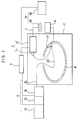
- FIG. 1 is a diagram of an embodiment of the discharge machining apparatus of the present invention.
- a discharge machining apparatus 1 is provided with a vacuum chamber 2, a discharge apparatus 3, a laser irradiation apparatus 4, a controller 5, an electrical power source 6 and a circuit 7.
- the pressure in the vacuum chamber 2 can be reduced to 3000 Pa or below, and the interior of the vacuum chamber 2 can accommodate a workpiece 8.
- the discharge apparatus 3 has an electrode 11 and an electrode controller 12.
- the electrode controller 12 pays out more of the electrode 11 to compensate for wear to the electrode 11, and controls the current supplied to the electrode 11 from the power source 6.
- the electrode controller 12 is controlled by the controller 5, which may be a computer, for example.
- the laser irradiation apparatus 4 is comprised of a laser-beam generator 13, a laser controller 14, an optical fiber 15 and an optical fiber controller 16.
- the laser-beam generator 13 may be an excimer laser, for example.
- the laser controller 14 controls the laser trigger timing.
- the optical fiber 15 is a flexible fiber that is used to guide the laser beam to the machining site on the workpiece.
- the optical fiber controller 16 controls the position and attitude of the optical fiber 15 so that the laser beam is guided to a desired machining site.
- the discharge machining apparatus 1 has a discharge confirmation apparatus 10, which is constituted by an apparatus for measuring discharge time delay to confirm induction guidance of a discharge.
- the discharge confirmation apparatus 10 has an ammeter 18 and a current waveform scope 19.
- the ammeter 18 is provided in the circuit 7 of the discharge apparatus 3.
- the optical fiber controller 16 is connected to the ammeter 18.
- a Rogowskii coil may be used to form the ammeter 18.
- the current waveform scope 19 may be an oscilloscope.
- the optical fiber controller 16 is used to adjust the attitude of the optical fiber 15 so that an end 20 of the optical fiber 15 faces the machining site 17.
- the laser controller 14 is then used to activate the laser beam generator 13 to produce a laser beam that is guided along the optical fiber 15 and thereby projected onto the site 17.
- a pulsed laser is used having a pulse width ranging from 10 ns to several hundred ns, and preferably is shorter than the duration time of the discharge current, described below. This takes place with the pressure in the vacuum chamber 2 has been reduced to 3000 Pa or below.
- the signal from the laser controller 14 triggering the laser is input to the controller 5 and the electrode controller 12.
- the reception of the trigger signal activates the electrode controller 12, generating a discharge from the electrode 11.
- the discharge is detected by the ammeter 18 measuring the discharge current.
- the waveform of the signal output by the ammeter 18 is read on the current waveform scope 19.
- the current waveform scope 19 outputs a signal to the controller 5, which calculates the time delay to the current waveform peak, relative to the timing of the input trigger signal stored in the controller 5.
- the controller 5 determines that the time delay is less than a predetermined value, the controller 5 signals that induction guidance of the discharge has taken place.
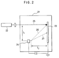
- a workpiece in the form of a brass plate forming a cathode 23 was arranged inside a vacuum chamber 21, facing an anode 24 inside the vacuum chamber 21 and an excimer laser 22 outside the vacuum chamber 21.
- the apparatus was used conduct an experiment in which the cathode 23 was irradiated with a laser beam 25 (from a 248 nm KrF laser) in 23 ns pulses at a radiation energy of from 5 to 189 mJ, and the laser beam was used to induction-guide a discharge to the point being irradiated.
- a laser beam 25 from a 248 nm KrF laser
- the distance I 1 from the anode 24 to the laser beam 25 was 30 mm, and experiments were conducted at a distance I 2 between anode 24 and cathode 23 of 30 mm, 60 mm and 90 mm.
- the anode 24 was covered copper wire 1 mm in diameter, with just 1 mm of the copper core being exposed so that discharge occurred only at that tip.
- the cathode 23 was a brass plate measuring 100 mm by 100 mm by 1 mm thick. For the experiment, voltages ranging from 200 V to 1 kV were applied across the electrodes, laser beam irradiation was carried out manually, and the pressure inside the vacuum chamber 21 was reduced to between 100 Pa and 1000 Pa.
- the laser beam 25 was projected onto the cathode 23 via a lens having a focal length of 300 mm, producing an irradiation spot measuring approximately 0.5 high by 4 mm across.
- the laser beam can be considered as having that degree of spread.
- a discharge is guided, as shown by arrow 26, there is an overlap between the laser irradiation spot and the discharge point.
- the discharge is regarded as not having been guided by the laser beam.
- Figure 3 shows the results obtained with respect to whether discharge was induction-guided, using a discharge distance I 2 (distance between cathode and anode) of 42 mm and irradiating the cathode with a laser radiation energy ranging from 10 to 160 mJ, at a reduced pressure of 600 Pa.
- a plot inside region A indicates a guided discharge
- plots in region B are of discharge that did take place but were not guided by the laser beam
- plots in region C are when discharge did not take place.
- the plots of Figure 5 indicate discharges that were guided by the laser beam, using a reduced pressure of 600 Pa and voltages ranging from 600 V to 1 kV.
- ⁇ indicate a guided discharge and ⁇ an unguided discharge. Whereas time Td was more or less 10 ⁇ s when a discharge was laser guided, when a discharge was not guided the time Td value was much larger, even at the same voltage, and became even larger at lower voltages.
- Figure 6 was produced using values obtained by dividing discharge distance I by time Td. A discharge does not follow a straight path, so the straight-line discharge distance from the tip of the anode to the discharge impact point was approximated. The same data was used for Figures 5 and 6. With voltages of 600 V and 700 V being typical for the unguided group, values that in Figure 5 seemed to indicate variation, were arranged in Figure 6. With the delay time increasing more or less proportionally to the increase in discharge distance, the velocity at discharge initiation can be regarded as constant. This is referred to as assumed initial discharge velocity (I/Td). With respect to Figure 6, discharges can be divided into guided and unguided discharges, with the assumed initial discharge velocity of guided discharges being 3 to 5 times higher than that of unguided discharges, at the same voltage.
- assumed initial discharge velocity I/Td
- time Td is shorter when a discharge is guided, under actual laser guided discharge machining conditions time Td can be used to monitor whether or not discharges are guided to the point being irradiated by the laser beam.
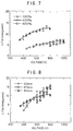
- Figures 7 and 8 are the results of an investigation of time Td characteristics during guided discharges, at different pressures and electrode-to-electrode distances (I 2 ). In the case of Figure 7 the distance between electrodes was 42 mm, and in the case of Figure 8 a pressure of 200 Pa was used.
- the graphs reveal that an increase in the voltage is accompanied by an increase in the assumed initial discharge velocity, and that since the course of the increase in the velocity closely matches an approximation based on a secondary curve, it follows that time Td is a value related to the field acceleration of charged particles. It is considered that the reason why an increase in pressure results in a decrease in the assumed initial discharge velocity is that it is caused by air molecules hindering the diffusion of charged particles produced by the laser beam, between the electrodes.
- the discharge machining apparatus of this invention can be used to machine the rear surface and other such parts of a workpiece, which is not possible with conventional discharge machining methods. Moreover, unlike conventional methods, this invention does not require the use of an electrode having the same shape as the shape to which the workpiece is to be machined. Furthermore, with this invention the machining contour is controlled by the laser beam spot points, without any need to move the electrode. Also, it can be confirmed whether a discharge has been guided as required by measuring the time delay at which discharge current reaches its peak. This makes it possible to precisely guide the discharge machining point by adjusting the machining condition settings, enabling precision machining. The machining operation is also facilitated by the fact that discharge timing can be controlled by laser.
Landscapes
- Engineering & Computer Science (AREA)
- Mechanical Engineering (AREA)
- Electrical Discharge Machining, Electrochemical Machining, And Combined Machining (AREA)
- Laser Beam Processing (AREA)
Claims (3)
- Lasergeführte Entladungsbearbeitungsvorrichtung, umfassend:eine Vakuumkammer (2), die ein Werkstück (8) aufnehmen kann und in der ein Zustand mit verringertem Druck von 3000 Pa oder darunter geschaffen werden kann,eine Entladungselektrode (11), die in der Vakuumkammer (2) aufgenommen ist und geladene Teilchen abgeben kann,einen Laser (4), der einen Laserstrahl in Richtung der Vakuumkammer emittiert,eine Laserführungsvorrichtung (15) zum Führen des Laserstrahls, um einen Teil (17) des Werkstücks (8) in der Vakuumkammer (2) zu bestrahlen, undeine Vorrichtung zum Messen einer Entladungsverzögerung (10) zum Detektieren einer Zeitverzögerung zwischen einem Zeitpunkt, bei dem die Laserbestrahlung ausgelöst wird, und einem Zeitpunkt, bei dem die Entladung von der Entladungselektrode stattfindet.
- Lasergeführte Entladungsbearbeitungsvorrichtung nach Anspruch 1, dadurch gekennzeichnet, daß die Vorrichtung zum Messen der Entladungsverzögerung (10) einen Entladungsstromdetektor (18, 19), einen Laser-Controller (13) und einen Computer (5) umfaßt, der ein Signal von dem Entladungsstromdetektor und ein Auslösesignal von dem Laser-Controller empfängt und eine Zeitverzögerung des Entladungsstromes berechnet.
- Lasergeführte Entladungsbearbeitungsvorrichtung nach Anspruch 1, dadurch gekennzeichnet, daß der Laserstrahl eine Impulsbreite aufweist, die Kleiner als die Zeitdauer des Entladungsstromes ist.
Applications Claiming Priority (2)
| Application Number | Priority Date | Filing Date | Title |
|---|---|---|---|
| JP286877/95 | 1995-10-06 | ||
| JP7286877A JP2708096B2 (ja) | 1995-10-06 | 1995-10-06 | レーザ放電誘導式放電加工の確認装置 |
Publications (2)
| Publication Number | Publication Date |
|---|---|
| EP0767025A1 EP0767025A1 (de) | 1997-04-09 |
| EP0767025B1 true EP0767025B1 (de) | 1999-04-21 |
Family
ID=17710165
Family Applications (1)
| Application Number | Title | Priority Date | Filing Date |
|---|---|---|---|
| EP96115823A Expired - Lifetime EP0767025B1 (de) | 1995-10-06 | 1996-10-02 | Gerät zur lasergeführten Funkenerodierbearbeitung |
Country Status (4)
| Country | Link |
|---|---|
| US (1) | US5676861A (de) |
| EP (1) | EP0767025B1 (de) |
| JP (1) | JP2708096B2 (de) |
| DE (1) | DE69602149T2 (de) |
Families Citing this family (2)
| Publication number | Priority date | Publication date | Assignee | Title |
|---|---|---|---|---|
| JP3829175B2 (ja) * | 2000-04-20 | 2006-10-04 | 独立行政法人産業技術総合研究所 | レーザ誘導放電によるスイッチング装置 |
| US9586279B2 (en) * | 2013-09-17 | 2017-03-07 | Kangmin Hsia | Method and system of surface polishing |
Family Cites Families (7)
| Publication number | Priority date | Publication date | Assignee | Title |
|---|---|---|---|---|
| CH664314A5 (de) * | 1983-05-02 | 1988-02-29 | Mitsubishi Electric Corp | Funkenerosionseinrichtung. |
| JPS60161029A (ja) * | 1984-02-01 | 1985-08-22 | Nec Corp | 放電間隙検出回路 |
| US4829153A (en) * | 1986-04-28 | 1989-05-09 | Battelle Memorial Institute | Welding arc initiator |
| DE3706124A1 (de) * | 1987-02-25 | 1988-09-08 | Agie Ag Ind Elektronik | Verfahren zum elektroerosiven bearbeiten von elektrisch schwach oder nicht leitenden werkstuecken sowie elektroerosionsmaschine zur durchfuehrung des verfahrens |
| JPH0761567B2 (ja) * | 1992-03-31 | 1995-07-05 | 工業技術院長 | 放電加工方法及び装置 |
| JPH0822483B2 (ja) * | 1993-08-05 | 1996-03-06 | 工業技術院長 | レーザ放電誘導式放電加工装置 |
| JPH08155670A (ja) * | 1994-12-05 | 1996-06-18 | Nippondenso Co Ltd | レーザ加工機とその加工方法 |
-
1995
- 1995-10-06 JP JP7286877A patent/JP2708096B2/ja not_active Expired - Lifetime
-
1996
- 1996-10-02 US US08/725,678 patent/US5676861A/en not_active Expired - Fee Related
- 1996-10-02 EP EP96115823A patent/EP0767025B1/de not_active Expired - Lifetime
- 1996-10-02 DE DE69602149T patent/DE69602149T2/de not_active Expired - Fee Related
Also Published As
| Publication number | Publication date |
|---|---|
| US5676861A (en) | 1997-10-14 |
| DE69602149T2 (de) | 1999-10-28 |
| JP2708096B2 (ja) | 1998-02-04 |
| DE69602149D1 (de) | 1999-05-27 |
| EP0767025A1 (de) | 1997-04-09 |
| JPH09103920A (ja) | 1997-04-22 |
Similar Documents
| Publication | Publication Date | Title |
|---|---|---|
| US5373135A (en) | Process and an arrangement for treating workpiece by means of laser radiation | |
| JP3306149B2 (ja) | レーザーから発せられるレーザー放射を用いて工作物を加工するための方法および装置 | |
| ES2128781T3 (es) | Aparato y metodo para soldar metales mediante el uso de un rayo laser. | |
| US3291959A (en) | Procedure and equipment for the automatic focussing of the charge carrier beam in devices for the working of materials by means of a charge carrier beam | |
| JPH03133588A (ja) | レーザビーム発生装置を用いた高精度貫通孔作製方法及び装置 | |
| JP3037404B2 (ja) | 貫通孔の大きさを測定するための方法と装置 | |
| KR100468810B1 (ko) | 레이저에 의한 아크유도방법 및 그것을 사용한 아크유도용접 및 장치 | |
| EP0261914A2 (de) | Verfahren und Vorrichtung zur Erzeugung eines Lichtbogens | |
| US4393295A (en) | Apparatus and method for engraving with an electron beam | |
| EP0767025B1 (de) | Gerät zur lasergeführten Funkenerodierbearbeitung | |
| US5496983A (en) | Laser guided discharge machining apparatus and method | |
| US4288679A (en) | Method of microdrilling metal workpieces using a power laser | |
| JP3946362B2 (ja) | レーザ誘導アーク溶接装置および同溶接方法 | |
| GB2045669A (en) | Method of microdrilling metal workpiece using a power laser | |
| JPH08155670A (ja) | レーザ加工機とその加工方法 | |
| DE4031545A1 (de) | Verfahren und vorrichtung zur herstellung einer texturwalze | |
| EP4202453A1 (de) | Laserinduziertes entladungsverfahren und system zur erzeugung einer steuerbaren hochspannungsentladung mit grosser reichweite | |
| US20050040149A1 (en) | Single head laser high throughput laser shock peening | |
| Khalil et al. | Generation of ion beams on a steel surface by laser radiation at various wavelengths under the presence of an applied electric field | |
| JP4289536B2 (ja) | レーザ光とアークを用いた溶融加工装置及び方法 | |
| JP3523111B2 (ja) | レーザトリガアーク溶接方法及び装置 | |
| Hoshi et al. | Time delay in laser-guided discharge at low air pressure | |
| JPS63140789A (ja) | アイレス縫合針の穴明け方法 | |
| Igarashi et al. | Effect of repetitive irradiation on ion saturation current of laser ablation plasma using 1 kHz repetitive laser | |
| Chang et al. | Laser-induced Plasma Detection for Laser Percussion Drilling of Stainless Steel and CoCrMo Alloy |
Legal Events
| Date | Code | Title | Description |
|---|---|---|---|
| PUAI | Public reference made under article 153(3) epc to a published international application that has entered the european phase |
Free format text: ORIGINAL CODE: 0009012 |
|
| AK | Designated contracting states |
Kind code of ref document: A1 Designated state(s): DE FR |
|
| 17P | Request for examination filed |
Effective date: 19970404 |
|
| GRAG | Despatch of communication of intention to grant |
Free format text: ORIGINAL CODE: EPIDOS AGRA |
|
| 17Q | First examination report despatched |
Effective date: 19980825 |
|
| GRAG | Despatch of communication of intention to grant |
Free format text: ORIGINAL CODE: EPIDOS AGRA |
|
| GRAG | Despatch of communication of intention to grant |
Free format text: ORIGINAL CODE: EPIDOS AGRA |
|
| GRAH | Despatch of communication of intention to grant a patent |
Free format text: ORIGINAL CODE: EPIDOS IGRA |
|
| GRAH | Despatch of communication of intention to grant a patent |
Free format text: ORIGINAL CODE: EPIDOS IGRA |
|
| GRAA | (expected) grant |
Free format text: ORIGINAL CODE: 0009210 |
|
| AK | Designated contracting states |
Kind code of ref document: B1 Designated state(s): DE FR |
|
| ET | Fr: translation filed | ||
| REF | Corresponds to: |
Ref document number: 69602149 Country of ref document: DE Date of ref document: 19990527 |
|
| PLBE | No opposition filed within time limit |
Free format text: ORIGINAL CODE: 0009261 |
|
| STAA | Information on the status of an ep patent application or granted ep patent |
Free format text: STATUS: NO OPPOSITION FILED WITHIN TIME LIMIT |
|
| 26N | No opposition filed | ||
| PGFP | Annual fee paid to national office [announced via postgrant information from national office to epo] |
Ref country code: FR Payment date: 20051014 Year of fee payment: 10 Ref country code: DE Payment date: 20051014 Year of fee payment: 10 |
|
| PG25 | Lapsed in a contracting state [announced via postgrant information from national office to epo] |
Ref country code: DE Free format text: LAPSE BECAUSE OF NON-PAYMENT OF DUE FEES Effective date: 20070501 |
|
| REG | Reference to a national code |
Ref country code: FR Ref legal event code: ST Effective date: 20070629 |
|
| PG25 | Lapsed in a contracting state [announced via postgrant information from national office to epo] |
Ref country code: FR Free format text: LAPSE BECAUSE OF NON-PAYMENT OF DUE FEES Effective date: 20061031 |