EP0766617B1 - A method and a plant for use in the production of a fibre reinforced three-dimensional product - Google Patents
A method and a plant for use in the production of a fibre reinforced three-dimensional product Download PDFInfo
- Publication number
- EP0766617B1 EP0766617B1 EP95922447A EP95922447A EP0766617B1 EP 0766617 B1 EP0766617 B1 EP 0766617B1 EP 95922447 A EP95922447 A EP 95922447A EP 95922447 A EP95922447 A EP 95922447A EP 0766617 B1 EP0766617 B1 EP 0766617B1
- Authority
- EP
- European Patent Office
- Prior art keywords
- mould
- frame
- fibres
- laminate
- product
- Prior art date
- Legal status (The legal status is an assumption and is not a legal conclusion. Google has not performed a legal analysis and makes no representation as to the accuracy of the status listed.)
- Expired - Lifetime
Links
- 238000000034 method Methods 0.000 title claims description 44
- 239000000835 fiber Substances 0.000 title claims description 24
- 238000004519 manufacturing process Methods 0.000 title claims description 7
- 238000003825 pressing Methods 0.000 claims description 20
- 230000002787 reinforcement Effects 0.000 claims description 18
- 239000011159 matrix material Substances 0.000 claims description 17
- 238000010438 heat treatment Methods 0.000 claims description 15
- 239000000463 material Substances 0.000 claims description 14
- 239000004033 plastic Substances 0.000 claims description 14
- 229920001169 thermoplastic Polymers 0.000 claims description 5
- 239000004416 thermosoftening plastic Substances 0.000 claims description 5
- 239000000047 product Substances 0.000 description 30
- 238000007596 consolidation process Methods 0.000 description 4
- 238000000151 deposition Methods 0.000 description 4
- 238000006073 displacement reaction Methods 0.000 description 3
- 238000001311 chemical methods and process Methods 0.000 description 2
- 239000007795 chemical reaction product Substances 0.000 description 2
- 238000007493 shaping process Methods 0.000 description 2
- 239000004593 Epoxy Substances 0.000 description 1
- 238000006243 chemical reaction Methods 0.000 description 1
- 238000005520 cutting process Methods 0.000 description 1
- 238000009826 distribution Methods 0.000 description 1
- 239000003365 glass fiber Substances 0.000 description 1
- 230000000977 initiatory effect Effects 0.000 description 1
- 238000000465 moulding Methods 0.000 description 1
- 229920000728 polyester Polymers 0.000 description 1
- 230000000284 resting effect Effects 0.000 description 1
- 238000009966 trimming Methods 0.000 description 1
Images


Classifications
-
- B—PERFORMING OPERATIONS; TRANSPORTING
- B29—WORKING OF PLASTICS; WORKING OF SUBSTANCES IN A PLASTIC STATE IN GENERAL
- B29C—SHAPING OR JOINING OF PLASTICS; SHAPING OF MATERIAL IN A PLASTIC STATE, NOT OTHERWISE PROVIDED FOR; AFTER-TREATMENT OF THE SHAPED PRODUCTS, e.g. REPAIRING
- B29C70/00—Shaping composites, i.e. plastics material comprising reinforcements, fillers or preformed parts, e.g. inserts
- B29C70/04—Shaping composites, i.e. plastics material comprising reinforcements, fillers or preformed parts, e.g. inserts comprising reinforcements only, e.g. self-reinforcing plastics
- B29C70/28—Shaping operations therefor
- B29C70/54—Component parts, details or accessories; Auxiliary operations, e.g. feeding or storage of prepregs or SMC after impregnation or during ageing
- B29C70/541—Positioning reinforcements in a mould, e.g. using clamping means for the reinforcement
-
- B—PERFORMING OPERATIONS; TRANSPORTING
- B29—WORKING OF PLASTICS; WORKING OF SUBSTANCES IN A PLASTIC STATE IN GENERAL
- B29C—SHAPING OR JOINING OF PLASTICS; SHAPING OF MATERIAL IN A PLASTIC STATE, NOT OTHERWISE PROVIDED FOR; AFTER-TREATMENT OF THE SHAPED PRODUCTS, e.g. REPAIRING
- B29C31/00—Handling, e.g. feeding of the material to be shaped, storage of plastics material before moulding; Automation, i.e. automated handling lines in plastics processing plants, e.g. using manipulators or robots
- B29C31/04—Feeding of the material to be moulded, e.g. into a mould cavity
- B29C31/08—Feeding of the material to be moulded, e.g. into a mould cavity of preforms to be moulded, e.g. tablets, fibre reinforced preforms, extruded ribbons, tubes or profiles; Manipulating means specially adapted for feeding preforms, e.g. supports conveyors
-
- B—PERFORMING OPERATIONS; TRANSPORTING
- B29—WORKING OF PLASTICS; WORKING OF SUBSTANCES IN A PLASTIC STATE IN GENERAL
- B29C—SHAPING OR JOINING OF PLASTICS; SHAPING OF MATERIAL IN A PLASTIC STATE, NOT OTHERWISE PROVIDED FOR; AFTER-TREATMENT OF THE SHAPED PRODUCTS, e.g. REPAIRING
- B29C51/00—Shaping by thermoforming, i.e. shaping sheets or sheet like preforms after heating, e.g. shaping sheets in matched moulds or by deep-drawing; Apparatus therefor
- B29C51/002—Shaping by thermoforming, i.e. shaping sheets or sheet like preforms after heating, e.g. shaping sheets in matched moulds or by deep-drawing; Apparatus therefor characterised by the choice of material
- B29C51/004—Textile or other fibrous material made from plastics fibres
-
- B—PERFORMING OPERATIONS; TRANSPORTING
- B29—WORKING OF PLASTICS; WORKING OF SUBSTANCES IN A PLASTIC STATE IN GENERAL
- B29C—SHAPING OR JOINING OF PLASTICS; SHAPING OF MATERIAL IN A PLASTIC STATE, NOT OTHERWISE PROVIDED FOR; AFTER-TREATMENT OF THE SHAPED PRODUCTS, e.g. REPAIRING
- B29C70/00—Shaping composites, i.e. plastics material comprising reinforcements, fillers or preformed parts, e.g. inserts
- B29C70/04—Shaping composites, i.e. plastics material comprising reinforcements, fillers or preformed parts, e.g. inserts comprising reinforcements only, e.g. self-reinforcing plastics
- B29C70/06—Fibrous reinforcements only
- B29C70/10—Fibrous reinforcements only characterised by the structure of fibrous reinforcements, e.g. hollow fibres
- B29C70/16—Fibrous reinforcements only characterised by the structure of fibrous reinforcements, e.g. hollow fibres using fibres of substantial or continuous length
- B29C70/20—Fibrous reinforcements only characterised by the structure of fibrous reinforcements, e.g. hollow fibres using fibres of substantial or continuous length oriented in a single direction, e.g. roofing or other parallel fibres
- B29C70/202—Fibrous reinforcements only characterised by the structure of fibrous reinforcements, e.g. hollow fibres using fibres of substantial or continuous length oriented in a single direction, e.g. roofing or other parallel fibres arranged in parallel planes or structures of fibres crossing at substantial angles, e.g. cross-moulding compound [XMC]
-
- B—PERFORMING OPERATIONS; TRANSPORTING
- B29—WORKING OF PLASTICS; WORKING OF SUBSTANCES IN A PLASTIC STATE IN GENERAL
- B29C—SHAPING OR JOINING OF PLASTICS; SHAPING OF MATERIAL IN A PLASTIC STATE, NOT OTHERWISE PROVIDED FOR; AFTER-TREATMENT OF THE SHAPED PRODUCTS, e.g. REPAIRING
- B29C70/00—Shaping composites, i.e. plastics material comprising reinforcements, fillers or preformed parts, e.g. inserts
- B29C70/04—Shaping composites, i.e. plastics material comprising reinforcements, fillers or preformed parts, e.g. inserts comprising reinforcements only, e.g. self-reinforcing plastics
- B29C70/28—Shaping operations therefor
- B29C70/30—Shaping by lay-up, i.e. applying fibres, tape or broadsheet on a mould, former or core; Shaping by spray-up, i.e. spraying of fibres on a mould, former or core
- B29C70/302—Details of the edges of fibre composites, e.g. edge finishing or means to avoid delamination
-
- Y—GENERAL TAGGING OF NEW TECHNOLOGICAL DEVELOPMENTS; GENERAL TAGGING OF CROSS-SECTIONAL TECHNOLOGIES SPANNING OVER SEVERAL SECTIONS OF THE IPC; TECHNICAL SUBJECTS COVERED BY FORMER USPC CROSS-REFERENCE ART COLLECTIONS [XRACs] AND DIGESTS
- Y10—TECHNICAL SUBJECTS COVERED BY FORMER USPC
- Y10S—TECHNICAL SUBJECTS COVERED BY FORMER USPC CROSS-REFERENCE ART COLLECTIONS [XRACs] AND DIGESTS
- Y10S425/00—Plastic article or earthenware shaping or treating: apparatus
- Y10S425/037—Perforate
-
- Y—GENERAL TAGGING OF NEW TECHNOLOGICAL DEVELOPMENTS; GENERAL TAGGING OF CROSS-SECTIONAL TECHNOLOGIES SPANNING OVER SEVERAL SECTIONS OF THE IPC; TECHNICAL SUBJECTS COVERED BY FORMER USPC CROSS-REFERENCE ART COLLECTIONS [XRACs] AND DIGESTS
- Y10—TECHNICAL SUBJECTS COVERED BY FORMER USPC
- Y10S—TECHNICAL SUBJECTS COVERED BY FORMER USPC CROSS-REFERENCE ART COLLECTIONS [XRACs] AND DIGESTS
- Y10S425/00—Plastic article or earthenware shaping or treating: apparatus
- Y10S425/038—Pre-form
-
- Y—GENERAL TAGGING OF NEW TECHNOLOGICAL DEVELOPMENTS; GENERAL TAGGING OF CROSS-SECTIONAL TECHNOLOGIES SPANNING OVER SEVERAL SECTIONS OF THE IPC; TECHNICAL SUBJECTS COVERED BY FORMER USPC CROSS-REFERENCE ART COLLECTIONS [XRACs] AND DIGESTS
- Y10—TECHNICAL SUBJECTS COVERED BY FORMER USPC
- Y10S—TECHNICAL SUBJECTS COVERED BY FORMER USPC CROSS-REFERENCE ART COLLECTIONS [XRACs] AND DIGESTS
- Y10S425/00—Plastic article or earthenware shaping or treating: apparatus
- Y10S425/048—Sheet clamping
Definitions
- the present invention relates to a method for producing a fibre reinforced three-dimensional product of a plastic material by using a mould in which the product is formed, wherein a plane laminate of crossing fibre arrangements is formed containing long fibres which are uniformly oriented and which are mixed with a plastic matrix.
- a method is known from US-A-5,312,579 for the manufacture of a laminate.
- prepreg plies each consists of unidirectional fibres. It is described that moulding stops are used and that the plies are arranged within the mould. It is the object to ensure that no air is entrapped in the laminate.
- Such potential for displacement in the material means that the orientation of the reinforcement fibres in the end product does not correspond to the orientation that the reinforcement fibres are given in the deposited plane laminate before a three-dimensional shape is applied to it.
- the orientation of the reinforcement fibres in the end product does not correspond to the orientation that the reinforcement fibres are given in the deposited plane laminate before a three-dimensional shape is applied to it.
- the percentage content of reinforcement fibres will fall and become less the larger the distance from a plane original laminate.
- this lower content of reinforcement fibres there will appear falling strength in such parts of the finished product.
- a three-dimensional product may take place by depositing a number of layers on a three-dimensional shape, such as described e.g. in US-A-4,404,156 and US-A-5,312,579.
- a method for a mass production industry would preferably use the method where a plane laminate is formed initially which is subsequently given its three-dimensional shape by pressing/deep pressing the previously formed laminate.
- the present invention is primarily intended for this method, but the method may also be used in the production of plane products or substantially plane products in which it is possible to provide the long fibres with a predefined orientation. In this manner, the finished product may be given various mechanical properties such as different strengths in different orientations.
- a method which is characterized in that the laminate is deposited loosely on a carrier net with first ends of the long fibres projecting out from the laminate, that the deposited product is heated, that only said first ends of the long fibres are secured by securing members in the edge area of the mould, the securing members being activated while second ends are free in the mould as they do not reach a diametrically opposite side of the mould, that the carrier net is released from the frame, that the heated plane laminate is pressed into the desired three-dimensional shape of the product under continued securing of the fibres at said first ends, and that the product is released and removed from the mould.
- An apparatus for use by the method comprises a mould which has members along its mould edges for securing the reinforcement fibres and which is characterized in that the apparatus comprises a carrier frame provided with a carrier net which is suspended in the frame and which serves as support for the loosely deposited fibre arrangements, and a pressing frame having members which cooperate with the mould members in securing the reinforcement fibres only at the first ends projecting out from the laminate.
- the fibre arrangement is secured in the mould by means of the cooperating securing members of the pressing frame and the mould at the first ends of the fibres, it is possible for the individual layer to move freely along the other sides and to a certain extent also in the plane during the application of a three-dimensional shape.
- the mould used will be a quadrangular mould and the free mobility is consequently possible along the other three sides of a fibre arrangement.
- the laminate is heated to the processing temperature that applies to the chosen matrix material. The heating will initiate a chemical reaction in the matrix material if a hardening plastic is used.
- the laminate is kept at the processing temperature of the chosen matrix material until the consolidation during the pressing has been completed.
- the individual layers of the deposited laminate When a pressure is established, the individual layers of the deposited laminate will enter into close contact with each other and since the matrix material will at the same time consolidate during the pressing, the product will be in its three-dimensional shape. During this shaping, the fibres will be secured at the first ends and consequently they will retain their orientation during and after the three-dimensional shaping. Even in the area that is given the largest distance away from the plane original laminate, the fibres will be evenly distributed throughout the product surface. As a result thereof, better and more well-defined mechanical properties may be obtained in the formed three-dimensional product.
- the mould used will frequently be a polygonal, preferably quadrangular one. It is possible, however, to use moulds with any outer contours. It only has to be ensured that the long fibres are only secured at their first ends and do not extend to a diametrically opposite mould edge.
- a laminate should preferably consist of at least four layers of fibre arrangements, each having a fixed direction of orientation.
- each subsequent fibre arrangement will be placed with the first ends of the fibres in a position corresponding to one of the sides of the mould edge.
- the succeeding layer will be placed with its first ends at a mould edge adjacent to the mould edge used for the layer deposited immediately before.
- a matrix of hardening plastic or thermoplastic may be used.
- epoxy or polyester is used as matrix.
- each thread of the net preferably consists of reinforcement fibres, which may be mixed with the same matrix as has been used in the fibre arrangement.
- the net thread may be composed of pure reinforcement fibres or be mixed with an alien matrix which is different from the matrix used in the fibre arrangement.
- the handling equipment is simplified.
- a surface of the mould which co-operates with a surface of the pressing frame which is simultaneously used for giving the product its three-dimensional shape.
- the carrier net may be released from the carrier frame and enter into the finished product when the pressing frame presses down onto and holds the laminate on holding surfaces of a mould.
- the carrier net is composed of reinforcement fibres corresponding to those used for the product, a particularly preferable application of the method is obtained.
- Figures 1-4 schematically show a carrier frame 1 for use by the method according to the invention.
- the mould of the embodiment shown consists of a quadrangular frame 2 in which a carrier net 3 is suspended (see figure 5).
- the frame 2 has a first frame side 4, a second frame side 5, a third frame side 6, and a fourth frame side 7.
- a laminate consisting of several layers is deposited.
- Figure 1 shows how a first layer of a fibre arrangement 8 with long unidirectional fibres mixed with plastic has been deposited with first ends 9 at a first frame side 4.
- the fibres 8 have such length that the second ends 10 of the fibres do not reach the diametrically opposite frame side (the third frame side 6).
- the next layer is deposited with first ends 9 of the fibres at the second frame side 5.
- the second ends 10 of the fibres 8 in the second layer will also not reach the diametrically opposite frame side (the fourth frame side 7). Thereafter the third layer of fibres 8 is deposited in a similar manner with the first ends 9 at the third frame side 6, such as seen in figure 3. Then the fourth layer is deposited with first ends 9 of the fibres 8 at the fourth frame side 7.
- the first ends 9 of the fibres 8 are projecting from the formed laminate whereas their second ends 10 will be disposed freely inside the formed laminate 18 (see figure 5).
- the laminate 18 lying on the carrier net 3 is carried to a succeeding process step, which is illustrated in figure 5.
- the laminate is heated by contact heating between two heated surfaces 11, 12 to a temperature immediately below the sticking temperature of the plastic.
- the temperature is as high as possible without the material sticking to the heating surfaces 11, 12 used.
- the carrier net 3 with the laminate 18 deposited thereon is carried to a further process step (not shown) in which the laminate is heated to the process temperature, preferably in a hot-air oven.
- the heating to the process temperature may take place by means of other heat sources, such as radiated heat.
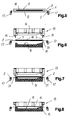
- the laminate thus heated is then carried to a process step shown in figure 6.
- the carrier frame 1 with the deposited laminate is introduced between a pressing frame 13, comprising a positive mould part 14, and a lower mould 15, comprising a negative mould part 16.
- the carrier net 3 is transported from the preceding process step and through a succeeding process step by means of transport equipment 17 supporting the frame 2.
- the transport equipment 17 is comprised of rails placed at such mutual distance that the formed laminate 18 is located in the middle of the carrier net 3 at a distance from the frame sides resting on the transport equipment 17.
- the heating members in the shape of the heating surfaces 11, 12 and the hot-air oven not shown to encircle the whole laminate without having to encircle the frame 2 and the transport equipment 17. If the frame 2 and the carrier equipment were to be located within the heating members, there would be heavy a thermal load and resulting attrition.
- the pressing frame 13 After the laminate 18 has been positioned between the pressing frame 13 and the mould 15, the pressing frame 13 is moved down towards the mould 15. This actuates the securing members in the shape of co-operating surfaces 19 on the pressing frame and a surface 20 on the mould 15. This situation is illustrated in figure 7. It appears therefrom that the securing members 19, 20 in the edge area of the mould 15 secure the first ends 10 of the long fibres of the respective fibre arrangements or layers in the laminate. The second ends 9 of the fibres will be disposed freely inside the laminate.
- FIG. 9 A more detailed view of a frame 2 provided with a carrier net 3 is seen in figures 9 and 10.
- Two opposite frame sides, optionally first and third or second and fourth frame sides, are formed by a profile 22 which allows transport of the frame by means of the automatic transport system 17 through the different process steps.
- the frame 2 has a plane upper surface 23.
- Pistons 24 extend through the upper surface 23 and are able to be displaced upwards over the plane upper surface 23 or to be displaced downwards under the plane upper surface 23 of the frame.
- the threads of the carrier net are put around the projecting pistons 24 in a way shown in figure 9.
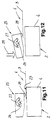
- FIGs 11 and 12 schematically show a second embodiment of the way in which the carrier net 3 is secured to the frame 2.
- the frame 2 is solely illustrated with its first frame side 4.
- the frame 2 has a plane upper surface 23.
- In the upper surface there may alternatively be provided tracks or grooves in which elastic flexible elements are mounted against which the carrier net 3 is secured.
- a clip 25 is used for each thread forming part of the carrier net 3.
- the clip 25 is fixed around an axis 26 and is connected with a torsion spring 28 which gives a force component 27 causing a projection 28 to become clasped against the plane upper surface 23 of the frame 2 in order to fasten a thread of the carrier net 3 between them.
- the carrier net 3 will be secured in the carrier frame 1.
- a force 29 is applied to the clip 25 so that it turns against the direction of the torsion force 27. In this manner the carrier net 3 is released.
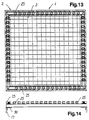
- FIG. 13 one sees a more detailed view of the frame 2 shown in figures 11 and 12 which is provided with the carrier net 3.
- Two opposite frame sides optionally the first and third or second and fourth frame sides, are provided at their bottom with a profile 30 allowing the transport of the carrier frame 1 by means of the automatic transport system 17 through the different process steps.
- the frame 2 is provided with a number of clips 25 functioning as described above with reference to figures 11, 12.
- the number of clips 25 and consequently of threads in the carrier net 3 may be varied according to requirements.
- Hardening plastic or thermoplastic may be used in the process. Heating must be done to different temperatures and serves different purposes, which will be known to a person skilled in the art. When using hardening plastic there will often be a requirement for a heating for initiation of the chemical process of consolidation of the laminate. If thermoplastic is used, the heating is required for accomplishing the very chemical process of laminate consolidation.
- hybrid yarn is understood to be a yarn consisting of the matrix material and the reinforcement fibres which are lying closely alongside each other like a yarn. It is also possible, however, to use generally known reinforcement fibres such as glass fibres.
- the carrier net 3 is formed from the same reinforcement fibres, which are mixed with the same matrix as used in the fibre arrangement. In this manner it is possible that the carrier net, which is released from the frame 2 such as described above, forms part of the finished three-dimensional product without being visible in the finished web. It is also possible to use a carrier net of other types of reinforcement fibres.
- the carrier net 3 is advantageously formed by means of supplies on rolls which are placed at one side and at one end of the carrier frame 2 and which are displaced automatically across the carrier frame either according to a pattern, in order to form one continuous fibre in the same manner as a racket is stringed, or just in order to provide one or two adjacent fibres in the carrier net. It is not essential how the carrier net is formed on the frame 2. This may also take place manually. It is important, however, that the carrier frame 2 is provided with the pistons 24 or similar members which make it possible to secure and release the carrier net during the process.
Landscapes
- Engineering & Computer Science (AREA)
- Mechanical Engineering (AREA)
- Chemical & Material Sciences (AREA)
- Composite Materials (AREA)
- Textile Engineering (AREA)
- Robotics (AREA)
- Moulding By Coating Moulds (AREA)
- Laminated Bodies (AREA)
- Casting Or Compression Moulding Of Plastics Or The Like (AREA)
- Manufacture Of Alloys Or Alloy Compounds (AREA)
- Blow-Moulding Or Thermoforming Of Plastics Or The Like (AREA)
Applications Claiming Priority (4)
| Application Number | Priority Date | Filing Date | Title |
|---|---|---|---|
| DK074094A DK171633B1 (da) | 1994-06-22 | 1994-06-22 | Fremgangsmåde samt anlæg til brug ved fremstilling af et fiberarmeret rumligt produkt |
| DK74094 | 1994-06-22 | ||
| DK740/94 | 1994-06-22 | ||
| PCT/DK1995/000260 WO1995035200A1 (en) | 1994-06-22 | 1995-06-22 | A method and a plant for use in the production of a fibre reinforced three-dimensional product |
Publications (2)
| Publication Number | Publication Date |
|---|---|
| EP0766617A1 EP0766617A1 (en) | 1997-04-09 |
| EP0766617B1 true EP0766617B1 (en) | 1998-07-29 |
Family
ID=8097000
Family Applications (1)
| Application Number | Title | Priority Date | Filing Date |
|---|---|---|---|
| EP95922447A Expired - Lifetime EP0766617B1 (en) | 1994-06-22 | 1995-06-22 | A method and a plant for use in the production of a fibre reinforced three-dimensional product |
Country Status (8)
| Country | Link |
|---|---|
| US (1) | US6030568A (da) |
| EP (1) | EP0766617B1 (da) |
| JP (1) | JPH10501754A (da) |
| AU (1) | AU2734295A (da) |
| DE (1) | DE69503786T2 (da) |
| DK (1) | DK171633B1 (da) |
| ES (1) | ES2119451T3 (da) |
| WO (1) | WO1995035200A1 (da) |
Families Citing this family (7)
| Publication number | Priority date | Publication date | Assignee | Title |
|---|---|---|---|---|
| ES2160282T3 (es) * | 1997-06-10 | 2001-11-01 | Trevira Gmbh | Un metodo y una planta para la produccion de un producto tridimensional reforzado con fibra. |
| US6835266B2 (en) * | 2001-08-02 | 2004-12-28 | Lear Corporation | Shuttle system for manufacturing vehicle headliners |
| US20050093188A1 (en) * | 2003-10-29 | 2005-05-05 | Forest Mark L.L. | Binderless preform manufacture |
| ES2260998B2 (es) * | 2004-03-26 | 2007-06-01 | Universidad Politecnica De Madrid | Metodo de moldeo por compresion de termoplasticos reforzados. |
| DE102014209524A1 (de) | 2014-05-20 | 2015-11-26 | Bayerische Motoren Werke Aktiengesellschaft | Positionierungskörper zum Positionieren eines Halbzeuges und Verfahren zum Präparieren des Halbzeuges sowie Halbzeug |
| DE102018115325A1 (de) * | 2018-06-26 | 2020-01-02 | Schmidt & Heinzmann Gmbh & Co. Kg | Vorformwerkzeug zumindest zu einer Herstellung eines Vorformlings eines Verbundbauteils |
| US20250018662A1 (en) | 2023-07-13 | 2025-01-16 | GM Global Technology Operations LLC | Carbon fiber compression molded parts with finished painted surfaces |
Family Cites Families (34)
| Publication number | Priority date | Publication date | Assignee | Title |
|---|---|---|---|---|
| US1595346A (en) * | 1926-08-10 | And walter a | ||
| US1482185A (en) * | 1919-04-14 | 1924-01-29 | Henry C Egerton | Molding process |
| US1587462A (en) * | 1919-11-04 | 1926-06-01 | Barrett Co | Process and apparatus for crimping plastic material |
| US1640543A (en) * | 1919-11-28 | 1927-08-30 | Westinghouse Electric & Mfg Co | Bushing and method of forming the same |
| US1638012A (en) * | 1924-04-11 | 1927-08-09 | Gen Electric | Blank for gears and method of making the same |
| US1601911A (en) * | 1924-09-22 | 1926-10-05 | Gen Electric | Textile-material gear and blank and method of making the same |
| US1913473A (en) * | 1929-10-07 | 1933-06-13 | Robert A Brennecke | Molded article |
| US2621140A (en) * | 1940-08-28 | 1952-12-09 | Comp Generale Electricite | Method for molding propeller blades |
| US2387778A (en) * | 1942-06-04 | 1945-10-30 | Stocking Willard Yates | Method of molding containers |
| US2417510A (en) * | 1943-03-22 | 1947-03-18 | Wheeling Stamping Co | Plastic article |
| US2844354A (en) * | 1954-04-08 | 1958-07-22 | Cincinnati Testing & Res Lab | Rotor blade and method of making same |
| DE1441362A1 (de) * | 1962-01-12 | 1969-01-16 | Helmut Roeck | Als Fussstuetze dienende Schuheinlage aus thermoplastischem Werkstoff sowie Verfahren und Vorrichtung zum Herstellen dieser Schuheinlage |
| US3621092A (en) * | 1969-02-20 | 1971-11-16 | Union Carbide Corp | Stamping process |
| US3651191A (en) * | 1969-10-29 | 1972-03-21 | Jack E Glatt | Method for molding plastic articles having imbedded indicia |
| GB1508383A (en) * | 1975-02-06 | 1978-04-26 | Nino Ag | Method for and device for use in the production of collar inserts |
| US4432716A (en) * | 1981-03-20 | 1984-02-21 | Lignotock Verfahrenstechnik Gmbh | Apparatus for moulding three-dimensionally shaped moulded articles from binder-containing web-like non-woven fabrics |
| US4404156A (en) * | 1981-08-03 | 1983-09-13 | Ogletree Ronald K | Method for making continuous fiber reinforced cast thermoplastic structures |
| JPS5945511B2 (ja) * | 1981-08-27 | 1984-11-07 | 池田物産株式会社 | 段ボ−ル製内装材の製造法 |
| DE3341292A1 (de) * | 1983-07-02 | 1985-01-03 | Bayer Ag, 5090 Leverkusen | Verfahren zur herstellung von faserverstaerkten formkoerpern |
| US4539249A (en) * | 1983-09-06 | 1985-09-03 | Textile Products, Incorporated | Method and apparatus for producing blends of resinous, thermoplastic fiber, and laminated structures produced therefrom |
| GB8512243D0 (en) * | 1985-05-15 | 1985-06-19 | Ici Plc | Shaped articles |
| GB8702847D0 (en) * | 1987-02-09 | 1987-03-18 | Ici Plc | Shaping of syntactic foam |
| US5066351A (en) * | 1987-05-20 | 1991-11-19 | The Boeing Company | Hot/cold press forming methods for shaping thermoformable materials |
| JPH01220661A (ja) * | 1988-02-24 | 1989-09-04 | Asano Kenkyusho:Kk | カツトシートの掴着装置 |
| FR2633213B1 (fr) * | 1988-06-27 | 1990-12-28 | Europ Propulsion | Procede de realisation d'une preforme fibreuse pour la fabrication de pieces en materiau composite ayant une forme complexe |
| WO1990009881A1 (en) * | 1989-02-28 | 1990-09-07 | Massachusetts Institute Of Technology | Method of producing a composite article |
| US5085928A (en) * | 1989-04-06 | 1992-02-04 | E. I. Dupont De Nemours And Company | Fiber reinforced composites comprising uni-directional fiber layers and aramid spunlaced fabric layers |
| US4946640A (en) * | 1989-04-17 | 1990-08-07 | Shell Oil Company | Method for forming preformed material |
| US5040962A (en) * | 1989-12-12 | 1991-08-20 | The Dow Chemical Company | Reaction injection molding apparatus with internal frame and shear edge |
| JPH04241915A (ja) * | 1991-01-14 | 1992-08-28 | Sumitomo Chem Co Ltd | 多層成形品の製造方法 |
| JP2695348B2 (ja) * | 1992-04-28 | 1997-12-24 | 大日本印刷株式会社 | 射出成形同時絵付装置 |
| JPH0729305B2 (ja) * | 1992-07-14 | 1995-04-05 | 富山県 | レジンインジェクション法によるfrpとその製造方法 |
| US5312579A (en) * | 1992-07-30 | 1994-05-17 | The United States Of America As Represented By The United States National Eronautics And Space Administration | Low pressure process for continuous fiber reinforced polyamic acid resin matrix composite laminates |
| US5639411A (en) * | 1994-12-21 | 1997-06-17 | Holli-Nee Corporation | Process for expanding glass fiber laminates and panels formed thereby |
-
1994
- 1994-06-22 DK DK074094A patent/DK171633B1/da not_active IP Right Cessation
-
1995
- 1995-06-22 DE DE69503786T patent/DE69503786T2/de not_active Expired - Fee Related
- 1995-06-22 EP EP95922447A patent/EP0766617B1/en not_active Expired - Lifetime
- 1995-06-22 WO PCT/DK1995/000260 patent/WO1995035200A1/en not_active Ceased
- 1995-06-22 US US08/765,266 patent/US6030568A/en not_active Expired - Fee Related
- 1995-06-22 AU AU27342/95A patent/AU2734295A/en not_active Abandoned
- 1995-06-22 JP JP8501512A patent/JPH10501754A/ja not_active Ceased
- 1995-06-22 ES ES95922447T patent/ES2119451T3/es not_active Expired - Lifetime
Also Published As
| Publication number | Publication date |
|---|---|
| WO1995035200A1 (en) | 1995-12-28 |
| DK171633B1 (da) | 1997-03-03 |
| US6030568A (en) | 2000-02-29 |
| DE69503786D1 (de) | 1998-09-03 |
| DE69503786T2 (de) | 1999-01-07 |
| JPH10501754A (ja) | 1998-02-17 |
| ES2119451T3 (es) | 1998-10-01 |
| EP0766617A1 (en) | 1997-04-09 |
| AU2734295A (en) | 1996-01-15 |
| DK74094A (da) | 1995-12-23 |
Similar Documents
| Publication | Publication Date | Title |
|---|---|---|
| US5217656A (en) | Method for making structural reinforcement preforms including energetic basting of reinforcement members | |
| US5908596A (en) | Process and apparatus for expanding and molding fiberglass laminate and the panel formed thereby | |
| US4486372A (en) | Method for fabricating contoured perforated composite laminate structure | |
| US5176949A (en) | Textile reinforcements for composite materials and method of manufacturing thereof | |
| ES2016254B3 (es) | Fabricacion de bocadillos y un metodo de hacer la fabricacion de bocadillos | |
| EP0766617B1 (en) | A method and a plant for use in the production of a fibre reinforced three-dimensional product | |
| EP0884153B1 (en) | A method for use in the production of a fiber reinforced three-dimensional product | |
| CA2001306A1 (en) | Process for producing preformable continuous strand mats | |
| US3476635A (en) | Graduated density filamentous mat | |
| US8273206B2 (en) | Method for continuously forming composite material shape member having varied cross-sectional shape | |
| US4515848A (en) | Materials and methods for making resin-rigidified articles | |
| US3873291A (en) | Method of producing glass fiber mats | |
| WO2001034361A1 (en) | A method for continuously producing expanded thermoformable materials | |
| JPH04288226A (ja) | テキスタイル コアと、その製造方法と、テキスタイル コアを用いて作られる複合製品 | |
| EP0835741A2 (en) | Manufacture of fibre reinforced composites | |
| MXPA96006128A (en) | A method and an apparatus to be used in the production of a three-dimensional product reinforced with fib | |
| US3322585A (en) | Method of making a condensed filamentous mat | |
| JP2003305719A (ja) | Frpのプリフォーム製造方法および製造装置 | |
| US5639411A (en) | Process for expanding glass fiber laminates and panels formed thereby | |
| WO1999015323A1 (en) | Method for fabricating a corrugated composite channel | |
| US5585455A (en) | Reinforcement composites for thermosetting polymer systems | |
| JPH02297425A (ja) | Frp中芯用素材と中芯材及びそれらを連続的に製造する方法 | |
| NL8801055A (nl) | Werkwijze voor het vervaardigen van een raatvormige kern voor een dichte samengestelde bouwplaat of elke andere sandwich-constructie. | |
| JPH0687168A (ja) | ガラス繊維プリフォーム | |
| JPH06134911A (ja) | ガラス繊維プリフォーム及びその製造方法 |
Legal Events
| Date | Code | Title | Description |
|---|---|---|---|
| PUAI | Public reference made under article 153(3) epc to a published international application that has entered the european phase |
Free format text: ORIGINAL CODE: 0009012 |
|
| 17P | Request for examination filed |
Effective date: 19961115 |
|
| AK | Designated contracting states |
Kind code of ref document: A1 Designated state(s): BE DE ES FR GB IT SE |
|
| GRAG | Despatch of communication of intention to grant |
Free format text: ORIGINAL CODE: EPIDOS AGRA |
|
| 17Q | First examination report despatched |
Effective date: 19971106 |
|
| GRAG | Despatch of communication of intention to grant |
Free format text: ORIGINAL CODE: EPIDOS AGRA |
|
| GRAH | Despatch of communication of intention to grant a patent |
Free format text: ORIGINAL CODE: EPIDOS IGRA |
|
| GRAH | Despatch of communication of intention to grant a patent |
Free format text: ORIGINAL CODE: EPIDOS IGRA |
|
| GRAA | (expected) grant |
Free format text: ORIGINAL CODE: 0009210 |
|
| AK | Designated contracting states |
Kind code of ref document: B1 Designated state(s): BE DE ES FR GB IT SE |
|
| ITF | It: translation for a ep patent filed | ||
| REF | Corresponds to: |
Ref document number: 69503786 Country of ref document: DE Date of ref document: 19980903 |
|
| ET | Fr: translation filed | ||
| REG | Reference to a national code |
Ref country code: ES Ref legal event code: FG2A Ref document number: 2119451 Country of ref document: ES Kind code of ref document: T3 |
|
| PLBE | No opposition filed within time limit |
Free format text: ORIGINAL CODE: 0009261 |
|
| STAA | Information on the status of an ep patent application or granted ep patent |
Free format text: STATUS: NO OPPOSITION FILED WITHIN TIME LIMIT |
|
| 26N | No opposition filed | ||
| REG | Reference to a national code |
Ref country code: GB Ref legal event code: IF02 |
|
| PGFP | Annual fee paid to national office [announced via postgrant information from national office to epo] |
Ref country code: BE Payment date: 20020531 Year of fee payment: 8 |
|
| PGFP | Annual fee paid to national office [announced via postgrant information from national office to epo] |
Ref country code: GB Payment date: 20030619 Year of fee payment: 9 |
|
| PGFP | Annual fee paid to national office [announced via postgrant information from national office to epo] |
Ref country code: ES Payment date: 20030623 Year of fee payment: 9 |
|
| PGFP | Annual fee paid to national office [announced via postgrant information from national office to epo] |
Ref country code: SE Payment date: 20030624 Year of fee payment: 9 |
|
| PGFP | Annual fee paid to national office [announced via postgrant information from national office to epo] |
Ref country code: FR Payment date: 20030627 Year of fee payment: 9 |
|
| PG25 | Lapsed in a contracting state [announced via postgrant information from national office to epo] |
Ref country code: BE Free format text: LAPSE BECAUSE OF NON-PAYMENT OF DUE FEES Effective date: 20030630 |
|
| BERE | Be: lapsed |
Owner name: *VESTERGAARD TORBEN Effective date: 20030630 |
|
| PG25 | Lapsed in a contracting state [announced via postgrant information from national office to epo] |
Ref country code: GB Free format text: LAPSE BECAUSE OF NON-PAYMENT OF DUE FEES Effective date: 20040622 |
|
| PG25 | Lapsed in a contracting state [announced via postgrant information from national office to epo] |
Ref country code: SE Free format text: LAPSE BECAUSE OF NON-PAYMENT OF DUE FEES Effective date: 20040623 Ref country code: ES Free format text: LAPSE BECAUSE OF NON-PAYMENT OF DUE FEES Effective date: 20040623 |
|
| PGFP | Annual fee paid to national office [announced via postgrant information from national office to epo] |
Ref country code: DE Payment date: 20040626 Year of fee payment: 10 |
|
| EUG | Se: european patent has lapsed | ||
| EUG | Se: european patent has lapsed | ||
| GBPC | Gb: european patent ceased through non-payment of renewal fee |
Effective date: 20040622 |
|
| PG25 | Lapsed in a contracting state [announced via postgrant information from national office to epo] |
Ref country code: FR Free format text: LAPSE BECAUSE OF NON-PAYMENT OF DUE FEES Effective date: 20050228 |
|
| REG | Reference to a national code |
Ref country code: FR Ref legal event code: ST |
|
| PG25 | Lapsed in a contracting state [announced via postgrant information from national office to epo] |
Ref country code: IT Free format text: LAPSE BECAUSE OF NON-PAYMENT OF DUE FEES;WARNING: LAPSES OF ITALIAN PATENTS WITH EFFECTIVE DATE BEFORE 2007 MAY HAVE OCCURRED AT ANY TIME BEFORE 2007. THE CORRECT EFFECTIVE DATE MAY BE DIFFERENT FROM THE ONE RECORDED. Effective date: 20050622 |
|
| REG | Reference to a national code |
Ref country code: ES Ref legal event code: FD2A Effective date: 20040623 |
|
| PG25 | Lapsed in a contracting state [announced via postgrant information from national office to epo] |
Ref country code: DE Free format text: LAPSE BECAUSE OF NON-PAYMENT OF DUE FEES Effective date: 20060103 |