EP0766231A2 - Durch Signalspitzenkodes angeregte lineare Prädiktion - Google Patents
Durch Signalspitzenkodes angeregte lineare Prädiktion Download PDFInfo
- Publication number
- EP0766231A2 EP0766231A2 EP96115299A EP96115299A EP0766231A2 EP 0766231 A2 EP0766231 A2 EP 0766231A2 EP 96115299 A EP96115299 A EP 96115299A EP 96115299 A EP96115299 A EP 96115299A EP 0766231 A2 EP0766231 A2 EP 0766231A2
- Authority
- EP
- European Patent Office
- Prior art keywords
- signal
- spike
- pitch
- innovation
- code
- Prior art date
- Legal status (The legal status is an assumption and is not a legal conclusion. Google has not performed a legal analysis and makes no representation as to the accuracy of the status listed.)
- Ceased
Links
Images

Classifications
-
- G—PHYSICS
- G10—MUSICAL INSTRUMENTS; ACOUSTICS
- G10L—SPEECH ANALYSIS TECHNIQUES OR SPEECH SYNTHESIS; SPEECH RECOGNITION; SPEECH OR VOICE PROCESSING TECHNIQUES; SPEECH OR AUDIO CODING OR DECODING
- G10L19/00—Speech or audio signals analysis-synthesis techniques for redundancy reduction, e.g. in vocoders; Coding or decoding of speech or audio signals, using source filter models or psychoacoustic analysis
- G10L19/04—Speech or audio signals analysis-synthesis techniques for redundancy reduction, e.g. in vocoders; Coding or decoding of speech or audio signals, using source filter models or psychoacoustic analysis using predictive techniques
- G10L19/08—Determination or coding of the excitation function; Determination or coding of the long-term prediction parameters
- G10L19/12—Determination or coding of the excitation function; Determination or coding of the long-term prediction parameters the excitation function being a code excitation, e.g. in code excited linear prediction [CELP] vocoders
-
- G—PHYSICS
- G10—MUSICAL INSTRUMENTS; ACOUSTICS
- G10L—SPEECH ANALYSIS TECHNIQUES OR SPEECH SYNTHESIS; SPEECH RECOGNITION; SPEECH OR VOICE PROCESSING TECHNIQUES; SPEECH OR AUDIO CODING OR DECODING
- G10L19/00—Speech or audio signals analysis-synthesis techniques for redundancy reduction, e.g. in vocoders; Coding or decoding of speech or audio signals, using source filter models or psychoacoustic analysis
- G10L19/04—Speech or audio signals analysis-synthesis techniques for redundancy reduction, e.g. in vocoders; Coding or decoding of speech or audio signals, using source filter models or psychoacoustic analysis using predictive techniques
- G10L19/08—Determination or coding of the excitation function; Determination or coding of the long-term prediction parameters
- G10L19/10—Determination or coding of the excitation function; Determination or coding of the long-term prediction parameters the excitation function being a multipulse excitation
-
- G—PHYSICS
- G10—MUSICAL INSTRUMENTS; ACOUSTICS
- G10L—SPEECH ANALYSIS TECHNIQUES OR SPEECH SYNTHESIS; SPEECH RECOGNITION; SPEECH OR VOICE PROCESSING TECHNIQUES; SPEECH OR AUDIO CODING OR DECODING
- G10L19/00—Speech or audio signals analysis-synthesis techniques for redundancy reduction, e.g. in vocoders; Coding or decoding of speech or audio signals, using source filter models or psychoacoustic analysis
- G10L2019/0001—Codebooks
- G10L2019/0004—Design or structure of the codebook
- G10L2019/0005—Multi-stage vector quantisation
Definitions
- This invention relates to speech compression using code-excited linear prediction (CELP), and has particular relation to CELP speech compression which uses a low bit rate.
- CELP code-excited linear prediction
- CELP speech compression exploits the fact that, in the time domain, the human vocal tract produces a sequence of sounds, and that each sound is easily divided into a sequence of very similar pitch intervals.
- a CELP codec compresses and reconstructs each pitch interval in a two step process: pitch prediction evaluation and innovation signal search.
- the pitch prediction evaluation step exploits a characteristic of all pitch intervals: for each pitch interval of the sound, taken at its fundamental pitch, the instantaneous normalized amplitude correlates closely with the instantaneous normalized amplitude at the same part of the previous pitch interval. Normalization means multiplying by some scale factor, and time shifting by some lag (or lead) factor. The instantaneous amplitude of the previous pitch interval is known, or can be synthesized with satisfactory fidelity. Therefore, the instantaneous amplitude of the current pitch interval can be synthesized with satisfactory fidelity even if only the scale and lag factors are known.
- innovation signal search step a search is made among a collection of signals, called innovation signals, for the best signal.
- the library of innovation signals is generally totally random. For each pitch interval of the sound, the innovation signal is selected which most closely approximates, moment to moment, a typical difference between the normalized amplitude of one pitch interval and the normalized amplitude of the previous pitch interval.
- the innovation signals are therefore inherently normalized.
- a suitable scale factor by which the innovation signal is to be multiplied must be established. It is often not necessary to further establish a lag factor for the innovation signal, but one can be provided if desired.
- the scale and lag factors from the pitch prediction step, and the scale factor and innovation signal from the innovation signal search step could be transmitted on a telephone line directly. They similarly could be directly recorded on a tape or other recording medium directly; "transmit,” as used herein, therefore includes “record,” and “receive” therefore includes “play back.” Regardless of whether transmission or recording is contemplated, however, direct transmission can be improved upon by coding.
- Each scale factor is coded in such a fashion that all scale factors in a particular range bin of scale factors are given a single code. A different code is provided for each range. Ranges of pitch lags are similarly coded. Selecting range boundaries may be done in any manner which the worker finds convenient. Good results may be obtained by selecting range boundaries which result in each code being transmitted about as often as any other code is transmitted.
- a code is also transmitted indicating which innovation signal was selected.
- the collection or library of innovation signals therefore forms a codebook, and the "innovation signal search step” is therefore often called the “innovation codebook search step”.
- the codes may be transmitted using analog technology, but digital transmission is preferred.
- CELP processing takes the innovation signal code and reverses it to produce the innovation signal. It takes the innovation scale factor code and reverses it to produce the innovation scale factor. It multiplies the innovation signal by the innovation scale factor to produce a synthesized scaled innovation signal. It takes the overall synthesized signal of the previous pitch interval, lags it by the pitch lag (reversed from the pitch lag code), and multiplies the result by the pitch scale factor (reversed from the pitch scale factor code) to produce a synthesized pitch signal. The synthesized pitch signal and the synthesized scaled innovation signal are added together to form the overall synthesized signal of the current pitch interval. This overall synthesized signal is applied to a linear predictive coding (LPC) synthesis filter.
- LPC linear predictive coding
- the coefficients of the LPC synthesis filter are adaptively selected at the transmitting (or recording) end, as is known in the art. These coefficients are coded, and the coefficient codes are transmitted with the other codes. The process is then repeated with the next set of codes: LPC filter coefficients, pitch lag, pitch scale factor, innovation index, and innovation scale factor.
- an approximate set of these five codes is selected, and the incoming actual speech is compared with speech from the synthesized signal produced from these five codes.
- the codes are then adaptively modified until the difference between the actual incoming speech and the speech from the synthesized signal (as determined by a perceptual weighting filter) reaches a minimum.
- the codes which produce this minimum difference are then transmitted (or recorded) to the receiving (or playback) end.
- the foregoing CELP process produces synthesized speech which is perceived by the human ear as intelligible, but not of high fidelity. Additional bits can be devoted to any or all of the five codes to obtain additional fidelity, but such bandwidth is expensive and not always available. What is needed is a way to get improved fidelity, as perceived by the human ear, without requiring additional bit bandwidth.
- the present invention provides improved perceived fidelity, without additional bit bandwidth, by exploiting the tautology that predicting a signal is possible only if the signal is predictable. Applicant has exploited this tautology by discovering a fundamental difference between the interior of a sound and the onset of the same sound. Once the sound is well under way, a subsequent pitch interval is reasonably predictable from the previous pitch interval. Before the onset of a sound, however, all that is available is white noise, or, worse, a pitch interval from an entirely different sound. These are not useful for predicting the first pitch interval of the new sound.
- the innovation signals could be used to predict the first pitch interval, but they do an inadequate job. They were, after all, carefully crafted to express typical differences between adjoining pitch intervals (after normalization for scale factor and lag) within the sound. They were not crafted to express typical differences between the (normalized) signal in the first pitch interval of the sound and the (normalized) white noise in the equivalent length of time immediately preceding the sound. It will not do, as a first step in the prediction process, to add a conventional innovation signal to the white noise. Some other first step in the prediction process must be used to predict the first pitch interval.
- Applicant has discovered that this may be done by replacing the conventional innovation signal with a spike. In the digital domain, this is expressed by a plus one followed by a minus one, or a plus two followed by two minus ones, or some similar pulse train. Applicant therefore provides a codebook of normalized spikes, each ready to be multiplied by a suitable scale factor (also coded). The best scaled spike is compared with the putative onset pitch interval, and the best scaled innovation signal (from the innovation codebook) is also compared with the putative onset pitch interval. If the scaled spike is the closer match, then an indication is transmitted that an onset pitch interval has been encountered, and that the code is from the spike codebook rather than the innovation codebook. Subsequent codes are sent from the innovation codebook.
- a suitable scale factor also coded
- pitch interval includes "combination of pitch intervals" as appropriate. This adds to the complexity of the system but, importantly, does not add to the bit rate.
- pitch interval is an onset pitch interval or an interior pitch interval.
- Several pitch intervals of synthesized speech may be compared with the corresponding pitch intervals of actual incoming speech. The best scaled spike (if any) and, indeed, the best onset pitch interval (if any), may then be selected.
- a well selected scaled spike at a well selected onset pitch interval has a beneficial effect across the entire sound, and not just at its onset.
- Spikes rather than the previous pitch interval, are commonly used as templates during the first pitch interval of a sound, when the previous pitch interval is usually little more than white noise.
- the spike is a good approximation of the difference between two pitch intervals within a sound; indeed, it may be a better approximation than any of the innovation signals.
- It adds very little to the bit rate to send a code for a spike rather than for an innovation signal, especially since there is no way to determine when the next sound will start and a spike will be, in effect, a necessity. Indeed, rather than forcing the apparatus to make the academic determination of whether a new sound has begun, it is both easier and more effective to simply ask whether the best approximation to the pitch interval at hand is a spike or a more conventional innovation signal.
- the spike codebook and the innovation codebook are of equal size, and that some indicator bit is used to toggle between them.
- the spike codebook is smaller, and the spike codebook and innovation codebook are merged into a single codebook.
- a single apparatus may then be used to apply gain and lag adjustments.
- the relative sizes of the spike portion and the innovation portion must be selected to maximize perceived fidelity. It will not do to say that the spike portion and the innovation portion must have equal sizes, and that one bit of the code must therefore be used to toggle between them. However, it also will not do to say that interior pitch intervals are much more frequent than onset pitch intervals, and that therefore the innovation portion must be much larger than the spike portion. This effectively eliminates spike coding. A trade-off must be made between their relative sizes. This can be done on a fixed basis or on an adaptive basis.
- codes from both the spike codebook (or portion) and the innovation codebook (or portion) can be sent for every pitch interval. This is not preferred for low bit rate applications, since it greatly increases the bit rate with only a modest increase in perceived fidelity. It may be desirable in moderate to high bit rate applications.
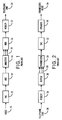
- Figure 1 is a block view of a prior art transmitter, or recorder, using CELP.
- Figure 2 is a block view of a prior art receiver, or playback device, using CELP.
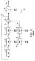
- Figure 3 is a block view of a prior art synthesizer used in the apparatus of Figure 2.
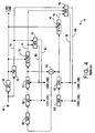
- Figure 4 is a block view of a prior art analyzer using a two step parameter extraction procedure to generate the parameters used to operate the apparatus shown in Figure 1.
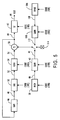
- Figure 5 is a block view of a synthesizer according to the present invention.
- Figure 6 is a block view of an analyzer according to the present invention.
- a voice 10 is applied to a microphone 12, the output of which is digitized by a analog-to-digital converter (ADC) 14.
- ADC analog-to-digital converter
- the digitized voice from the ADC 14 is applied to an analyzer 16, which produces a plurality of codes 18.
- the codes 18 are multiplexed by a multiplexer (MUX) 20, the output of which is modulated by a modem 22, the output of which is connected to a telephone line 24.
- MUX multiplexer
- a digital signal on the telephone line 24 is demodulated by the modem 24.
- a demultiplexer (DEMUX) 28 demultiplexes the demodulated signal into its component plurality of codes 18.
- the codes 18 drive a synthesizer 30 to synthesize a digital reproduction of the original voice 10.
- the digital reproduction is applied to a digital-to-analog converter (DAC) 32, which drives a speaker 34 which produces a synthesized voice 36 which is quite close to the original voice 10.
- DAC digital-to-analog converter
- Figure 3 shows the synthesizer 30 used by the prior art.
- the codes 18 shown in Figures 1 and 2 are specified as codes 18A through 18E for ease of identification.
- An innovation signal code 18A drives an innovation signal codebook 38, which reproduces and outputs an innovation signal 40.
- An innovation scale factor code 18B drives a gain, or scale factor, element 42 which reproduces an innovation scale factor and multiplies it by the innovation signal 40 to produce a scaled innovation signal 44.
- a memory 46 is outputting an overall synthesized signal 48, which it has stored from the previous pitch interval.
- the memory 46 must be able to be quickly written to or read from.
- a random access memory (RAM) or first-in-first-out memory (FIFO) is preferred.
- a lag element 50 receives the previous overall synthesized signal 48, lags (or leads) it by a factor which it reproduces from a lag factor code 18C, and outputs a lagged pitch signal 52.
- the lagged pitch signal 52 is applied to a pitch scale factor, or gain, unit 54, which multiplies it by a pitch scale factor which it reproduces from a pitch scale factor code 18D.
- the pitch gain unit 54 outputs a scaled pitch signal 56, which is applied to a summer 58.
- the summer 58 also receives the scaled innovation signal 44, and outputs the sum 60 to the RAM 46 as the new overall synthesized signal. If desired, the lag element 50 and gain element 54 may be reversed.
- the sum 60 is also applied to a synthesis filter (SF) 62.
- the SF 62 includes apparatus to receive LPC codes 18E, decode them into tap weights, and apply the tap weights to the SF 62 proper.
- the SF 62 produces the overall output signal 64 of the synthesizer 30.
- FIG. 4 shows the prior art method of producing the codes 18 in an analyzer 16.
- the codes 18 may be a series of scalar quantization (SQ) indices, or a single vector quantization (VQ) index, all as is known in the art.
- Digitized input speech 66 is applied both to a linear prediction analysis and coding (LPC) device 68 and to a perceptual weighting filter (PWF) 70.
- LPC linear prediction analysis and coding
- PWF perceptual weighting filter
- One of the SQ indices, or one of the components of the VQ index, is an LPC code 18E, which sets the tap weights of the PWF 70 and thereby allows the PWF 70 to produce a digitized signal as it would be perceived by a human being, all as is known in the art.
- the LPC code 18E is also applied to, and provides tap weights for, a first (pitch) synthesis filter and perceptual weighting filter (SF&PWF) 72, the output 74 of which is combined with the output 76 of the PWF 70 in a pitch minimizer 78.
- the pitch minimizer 78 produces two outputs, 80 and 82, which indirectly drive the SF&PWF 72, in such a fashion as to minimize the difference between the output 74 and the output 76; that is, the SF&PWF 72 is driven to emulate the PWF 70 as closely as possible.
- the output 80 is the pitch scale factor code 18D, and is applied to a gain element 84.
- the output 82 is the pitch lag code 18C, and is applied to a lag element 86.
- the lag element 86 drives the gain element 84, and is driven by a memory 88, which is, as before, preferably a RAM or FIFO.
- the RAM 88 holds an overall synthesized signal for one pitch interval, and is driven by a summer 90.
- the summer 90 receives the output of the pitch gain element 84 and the output of the innovation gain element, described below. As with the lag element 50 and gain element 54 of Figure 3, it is possible to reverse the lag element 86 and gain element 84 of Figure 4.
- the LPC code 18E is further applied to set the tap weights of a second (innovation) SF&PWF 92, the output 94 of which is combined, in a second (innovation) minimizer 96, both with the output 76 of the PWF 70 and with the output 74 of the first SF&PWF 72.
- the second minimizer 96 produces two outputs, 98 and 100, which indirectly drive the second SF&PWF 92, in such a fashion as to minimize the difference between the output 94 and some combination of the outputs 74 and 76; that is, the second SF&PWF 92 is driven to emulate the combination of the PWF 70 and the first SF&PWF 72 as closely as possible.
- the output 98 is the innovation scale factor code 18B, and is applied to a innovation gain, or scale factor, element 102.
- the output 100 is the innovation signal code 18A, and is applied to a innovation signal codebook 104.
- the innovation signal codebook 104 drives the gain element 102.
- Figure 5 shows an embodiment of the synthesizer 30 in the receiver portion of the present invention. It is identical to Figure 3, except that there is the addition of a spike code 18F, which drives a spike codebook 106 to produce a spike signal 108. There is also added a spike gain code 18G, which drives a spike gain element 110 to reproduce a spike gain and multiply it by the spike signal 108 to produce a scaled spike signal 112.
- a selector switch 114 selects whether the scaled innovation signal 44 or the scaled spike signal 112 is to be applied to the summer 58.
- Figure 6 shows an embodiment of the analyzer 10 in the transmitter portion of the present invention. It is identical to Figure 4, except that it shows additional apparatus for generating the spike signal code 18F, spike gain code 18G, and indicator code for the switch 114.
- the digitized input signal not only drives the LPC 68 and PWF 70; it also drives an LPC analysis filter (AF) 116 which, like the other filters, gets its tap weights from the LPC code 18E generated by the LPC 68.
- the output 118 of the AF 116 is an LPC residual signal, and drives a third minimizer, which (like the other minimizers) produces two outputs, 122 and 124.
- the output 122 drives a gain element 126 and the output 124 drives a spike codebook 128.
- the output 124 is the spike code 18F, and causes the spike codebook 128 to reproduce a spike signal 130.
- the output 122 is the spike gain code 18G, and causes the spike gain, or scale factor, element 126 to reproduce a spike gain, which it multiplies by the spike signal 130 to produce a scaled spike signal 132.
- the third minimizer 120 seeks to minimize the difference between the scaled spike signal 132 and the output 118 of the AF 116. This is done in the LPC residual domain, before the scaled spike signal 118 is applied to a third SF&PWF 134.
- the first (pitch) minimizer 78 does its work after the signal passes through the first SF&PWF 72, just as the second (innovation) minimizer 96 does its work after the signal passes through the second SF&PWF 92.
- the pitch minimizer 78 no longer drives the output of the first (pitch) SF&PWF 72 to emulate that of the PWF 70; it now must emulate some combination of the outputs of the PWF 70 and the third (spike) SF&PWF 134.
- the innovation minimizer 96 no longer drives the output of the second (innovation) SF&PWF 92 to emulate that of a combination of the PWF 70 and the first SF&PWF 72; it now must emulate some combination of the outputs of the PWF 70, the first SF&PWF 72, and the third SF&PWF 134.
- the second (innovation) minimizer 96 is in the position to determine how well the outputs of the SF&PWFs 72, 92, and 134 match that of the PWF 70.
- the output of the pitch SF&PWF 72 must always be considered, but the choice on how to select between the innovation SF&PWF 92 and the spike SF&PWF 134 can be made on a pitch interval to pitch interval basis.
- the second minimizer 96 activates a control device 138 to tell the selector switch 114 ( Figure 5) to receive the spike output 112, and to tell the first minimizer 78 to consider the spike output 136. If the spike output 136 is less valuable than the innovation output 94, then the switch 114 is set to receive the innovation output 44, and the first minimizer 78 is set to disregard the spike signal 136 by receiving the same signal from control device 138.
- the RAM 88 in the transmitting analyzer shown in Figure 6 may store the overall synthesized signal 48 from only the immediately preceding pitch interval, or it may store a combination of such overall synthesized signals 48 from several preceding pitch intervals. If the latter option is chosen, the RAM 88 includes additional apparatus for combining the overall synthesized signals 48 from the several preceding pitch intervals and for storing the combination. In this situation, the RAM 46 in the receiving synthesizer shown in Figure 5 includes parallel additional apparatus for combining the overall synthesized signals 48 from the same several preceding pitch intervals and for storing the same combination.
- the invention relates to a method speech over a narrow bandwidth channel the method comprising the steps of:
Landscapes
- Engineering & Computer Science (AREA)
- Computational Linguistics (AREA)
- Signal Processing (AREA)
- Health & Medical Sciences (AREA)
- Audiology, Speech & Language Pathology (AREA)
- Human Computer Interaction (AREA)
- Physics & Mathematics (AREA)
- Acoustics & Sound (AREA)
- Multimedia (AREA)
- Compression, Expansion, Code Conversion, And Decoders (AREA)
Applications Claiming Priority (2)
| Application Number | Priority Date | Filing Date | Title |
|---|---|---|---|
| US536329 | 1995-09-29 | ||
| US08/536,329 US5664054A (en) | 1995-09-29 | 1995-09-29 | Spike code-excited linear prediction |
Publications (2)
| Publication Number | Publication Date |
|---|---|
| EP0766231A2 true EP0766231A2 (de) | 1997-04-02 |
| EP0766231A3 EP0766231A3 (de) | 1998-06-17 |
Family
ID=24138066
Family Applications (1)
| Application Number | Title | Priority Date | Filing Date |
|---|---|---|---|
| EP96115299A Ceased EP0766231A3 (de) | 1995-09-29 | 1996-09-24 | Durch Signalspitzenkodes angeregte lineare Prädiktion |
Country Status (3)
| Country | Link |
|---|---|
| US (1) | US5664054A (de) |
| EP (1) | EP0766231A3 (de) |
| JP (1) | JPH09190198A (de) |
Families Citing this family (4)
| Publication number | Priority date | Publication date | Assignee | Title |
|---|---|---|---|---|
| US6449590B1 (en) * | 1998-08-24 | 2002-09-10 | Conexant Systems, Inc. | Speech encoder using warping in long term preprocessing |
| US6954727B1 (en) * | 1999-05-28 | 2005-10-11 | Koninklijke Philips Electronics N.V. | Reducing artifact generation in a vocoder |
| US8447592B2 (en) * | 2005-09-13 | 2013-05-21 | Nuance Communications, Inc. | Methods and apparatus for formant-based voice systems |
| CN101283407B (zh) | 2005-10-14 | 2012-05-23 | 松下电器产业株式会社 | 变换编码装置和变换编码方法 |
Family Cites Families (4)
| Publication number | Priority date | Publication date | Assignee | Title |
|---|---|---|---|---|
| JP2707564B2 (ja) * | 1987-12-14 | 1998-01-28 | 株式会社日立製作所 | 音声符号化方式 |
| US5233660A (en) * | 1991-09-10 | 1993-08-03 | At&T Bell Laboratories | Method and apparatus for low-delay celp speech coding and decoding |
| IT1264766B1 (it) * | 1993-04-09 | 1996-10-04 | Sip | Codificatore della voce utilizzante tecniche di analisi con un'eccitazione a impulsi. |
| EP0654909A4 (de) * | 1993-06-10 | 1997-09-10 | Oki Electric Ind Co Ltd | Celp kodierer und dekodierer. |
-
1995
- 1995-09-29 US US08/536,329 patent/US5664054A/en not_active Expired - Lifetime
-
1996
- 1996-09-24 EP EP96115299A patent/EP0766231A3/de not_active Ceased
- 1996-09-26 JP JP8254230A patent/JPH09190198A/ja not_active Withdrawn
Also Published As
| Publication number | Publication date |
|---|---|
| EP0766231A3 (de) | 1998-06-17 |
| JPH09190198A (ja) | 1997-07-22 |
| US5664054A (en) | 1997-09-02 |
Similar Documents
| Publication | Publication Date | Title |
|---|---|---|
| KR0169020B1 (ko) | 음성부호화장치, 음성복호화장치, 음성부호화복호화방법 및 이들에 사용가능한 위상진폭특성 도출장치 | |
| KR100361236B1 (ko) | 차분코딩원리를구현하는전송시스템 | |
| JPS6161305B2 (de) | ||
| EP0477960B1 (de) | Sprachcodierung durch lineare Prädiktion mit Anhebung der Hochfrequenzen | |
| JP2707564B2 (ja) | 音声符号化方式 | |
| US5488704A (en) | Speech codec | |
| US5504832A (en) | Reduction of phase information in coding of speech | |
| US4985923A (en) | High efficiency voice coding system | |
| US5737367A (en) | Transmission system with simplified source coding | |
| US5664054A (en) | Spike code-excited linear prediction | |
| JPH09185397A (ja) | 音声情報記録装置 | |
| JP3329216B2 (ja) | 音声符号化装置及び音声復号装置 | |
| JP2000132193A (ja) | 信号符号化装置及び方法、並びに信号復号装置及び方法 | |
| JPS61180299A (ja) | コ−デツク変換装置 | |
| JPH08234795A (ja) | 音声符号化装置 | |
| US20030158730A1 (en) | Method and apparatus for embedding data in and extracting data from voice code | |
| JPH02146100A (ja) | 音声符号化・復号化装置 | |
| JP3845316B2 (ja) | 音声符号化装置及び音声復号装置 | |
| JP3010655B2 (ja) | 圧縮符号化装置及び方法、並びに復号装置及び方法 | |
| JP4179232B2 (ja) | 音声符号化装置及び音声復号装置 | |
| JPH08328598A (ja) | 音声符号化・復号化装置 | |
| JPH11145846A (ja) | 信号圧縮伸張装置及び方法 | |
| JPH043878B2 (de) | ||
| CA2193345C (en) | Speech encoding and decoding capable of improving a speech quality | |
| JP2973966B2 (ja) | 音声通信装置 |
Legal Events
| Date | Code | Title | Description |
|---|---|---|---|
| PUAI | Public reference made under article 153(3) epc to a published international application that has entered the european phase |
Free format text: ORIGINAL CODE: 0009012 |
|
| AK | Designated contracting states |
Kind code of ref document: A2 Designated state(s): DE FR GB |
|
| PUAL | Search report despatched |
Free format text: ORIGINAL CODE: 0009013 |
|
| AK | Designated contracting states |
Kind code of ref document: A3 Designated state(s): DE FR GB |
|
| 17P | Request for examination filed |
Effective date: 19981214 |
|
| GRAG | Despatch of communication of intention to grant |
Free format text: ORIGINAL CODE: EPIDOS AGRA |
|
| RIC1 | Information provided on ipc code assigned before grant |
Free format text: 7G 10L 19/12 A |
|
| 17Q | First examination report despatched |
Effective date: 20001124 |
|
| RAP1 | Party data changed (applicant data changed or rights of an application transferred) |
Owner name: CONEXANT SYSTEMS, INC. |
|
| STAA | Information on the status of an ep patent application or granted ep patent |
Free format text: STATUS: THE APPLICATION HAS BEEN REFUSED |
|
| 18R | Application refused |
Effective date: 20010604 |