EP0766196A2 - Mehrstufiger elektrographischer Druck - Google Patents
Mehrstufiger elektrographischer Druck Download PDFInfo
- Publication number
- EP0766196A2 EP0766196A2 EP96115633A EP96115633A EP0766196A2 EP 0766196 A2 EP0766196 A2 EP 0766196A2 EP 96115633 A EP96115633 A EP 96115633A EP 96115633 A EP96115633 A EP 96115633A EP 0766196 A2 EP0766196 A2 EP 0766196A2
- Authority
- EP
- European Patent Office
- Prior art keywords
- pixels
- opposing edges
- center line
- grayscale
- determining
- Prior art date
- Legal status (The legal status is an assumption and is not a legal conclusion. Google has not performed a legal analysis and makes no representation as to the accuracy of the status listed.)
- Withdrawn
Links
Images

Classifications
-
- G—PHYSICS
- G06—COMPUTING OR CALCULATING; COUNTING
- G06K—GRAPHICAL DATA READING; PRESENTATION OF DATA; RECORD CARRIERS; HANDLING RECORD CARRIERS
- G06K15/00—Arrangements for producing a permanent visual presentation of the output data, e.g. computer output printers
- G06K15/02—Arrangements for producing a permanent visual presentation of the output data, e.g. computer output printers using printers
- G06K15/12—Arrangements for producing a permanent visual presentation of the output data, e.g. computer output printers using printers by photographic printing, e.g. by laser printers
- G06K15/1238—Arrangements for producing a permanent visual presentation of the output data, e.g. computer output printers using printers by photographic printing, e.g. by laser printers simultaneously exposing more than one point
- G06K15/1242—Arrangements for producing a permanent visual presentation of the output data, e.g. computer output printers using printers by photographic printing, e.g. by laser printers simultaneously exposing more than one point on one main scanning line
- G06K15/1252—Arrangements for producing a permanent visual presentation of the output data, e.g. computer output printers using printers by photographic printing, e.g. by laser printers simultaneously exposing more than one point on one main scanning line using an array of light modulators, e.g. a linear array
-
- G—PHYSICS
- G06—COMPUTING OR CALCULATING; COUNTING
- G06T—IMAGE DATA PROCESSING OR GENERATION, IN GENERAL
- G06T11/00—Two-dimensional [2D] image generation
- G06T11/20—Drawing from basic elements
- G06T11/23—Drawing from basic elements using straight lines or curves
-
- G—PHYSICS
- G06—COMPUTING OR CALCULATING; COUNTING
- G06K—GRAPHICAL DATA READING; PRESENTATION OF DATA; RECORD CARRIERS; HANDLING RECORD CARRIERS
- G06K2215/00—Arrangements for producing a permanent visual presentation of the output data
- G06K2215/0002—Handling the output data
- G06K2215/004—Generic data transformation
- G06K2215/006—Anti-aliasing raster data
Definitions
- This invention relates generally to digital printing systems, and more particularly, to a method of reducing aliasing effects.
- a light modulator or other imaging device may be used.
- the imaging device has an array of pixels as wide as the printed image. These pixels are addressed with data, which indicates the exposure for each pixel.
- the drum rotates so that one line of the drum is exposed by a line of pixels during each line period.
- gray scaling can be done by varying the exposure at points on the drum to control the amount of toner on any point.
- One way to vary the exposure is to re-expose the same line of the drum by successive lines of pixels. As the drum rotates, overlapping exposures are accumulated on it. Each line is re-exposed for as many times as is desired for a given grayscale capability.
- This approach to providing grayscale is referred to as "multi-level" printing. Its main limitation is that it permits only a limited number of levels of gray.
- the traditional solution to reduce aliasing is to increase the resolution, such as from 300 dpi (dots per inch) to 400 or 600 dpi. Problems with this approach are the need for more refined electrophotographic processes and high system overhead in terms of memory and bandwidth.
- aliasing can be reduced with techniques using grayscale. For example, pixels on edges of a black colored object can be colored gray so that the stair stepping is not as evident.
- their font bit-maps include outline pixels having grayscale levels that reduce aliasing. The selection of these grayscale levels is the result of ad hoc and experimental decision making on a character by character basis.
- One aspect of the invention is a method of reducing aliasing on a digital printer capable of printing an image with grayscale values.
- the method is designed for printing objects that are represented by graphical description data that describes at least two opposing edges of the object, such as alphanumeric characters or graphics primitives.
- a "center line" between two opposing edges is calculated from the graphic description data.
- Pixels are assigned to any area entirely overlapped by the object or on opposing edges.
- a grayscale of maximum intensity is assigned to pixels entirely overlapped by the object.
- Grayscale values are assigned to pixels on the opposing edges by identifying pairs of "opposing pixels" with respect to the center line. For each pair of opposing pixels, a grayscale level is assigned to a first pixel so as to compensate for the grayscale level of the other pixel.
- An advantage of the invention is that it provides an alternative to increased resolution as a solution to aliasing. It reduces the effects of aliasing without causing lines to appear thicker or thinner than their "true" width.
- anti-aliasing algorithms can be based on center line data, as well as on data representing the distance between opposing edges (line width). These algorithms provide a better alternative to anti-aliasing than the existing ad hoc "hinting" schemes widely used for fonts.
- the invention described herein is in terms of use with an electrophotographic printer, specifically, one in which a photoconductive drum is exposed by light from a spatial light modulator.
- the invention is also useful with electrophotographic printers with other exposure devices.
- the printer need not be electrophotographic, and can be any printer that provides grayscale images from digital data.
- the invention is directed to a method of providing grayscale values to reduce the effect of aliasing when printing objects, such as alphanumeric characters, that have opposing edges.
- FIGURE 1 illustrates a printing system 10 having a processor 10 programmed to implement the method of the invention.
- a drum 17 is exposed with a spatial light modulator (SLM) 15 having an array of pixels.
- SLM spatial light modulator
- Processor 11 receives graphical description data for objects to be printed. As explained below, processor 11 uses this data to determine center lines for the objects. It may also use the graphical description data to determine line width. In either case, center line data and line width data is used algorithmically to determine grayscale levels for pixels on edges (for controlling line width) or on the center line (for simulating embossed print). Processor 11 accesses look-up tables 12 to convert the grayscale values to exposure values. These values may directly represent exposure levels, or some other process may be used to obtain exposure levels. U.S.
- Patent No.5,461,411, entitled “Grayscale Printing Using Spatial Light Modulators”, assigned to Texas Instruments Incorporated describes various methods for exposing a drum with a digital micro-mirror device, a type of spatial light modulator.
- the exposure values are stored in an exposure data memory 13 in a format appropriate for delivery to the SLM 15.
- the SLM 15 is illuminated by a light source 14, and appropriate optics 16 are used to transfer the SLM image to the drum 17.
- FIGURE 2 illustrates a portion of a character "T" printed in accordance with the invention.
- a grid of pixels 21 that will be printed (or not printed) to form the character are also shown.
- each pixel 21 that is completely overlapped by character is solid black.
- each pixel 21 that falls on the edge of the character is some shade of gray.
- the level of grayscale for each pixel that falls on an edge is determined by calculating a center line, CL, within the character and by identifying "opposing pixels", such as P1 and P2, with respect to the center line.
- FIGURE 3 illustrates the determination of the "center lines” of the character of FIGURE 2.
- Alphanumeric characters, such as the T of FIGURE 2 are "closed” in the sense that they are defined by a closed edge. These characters can be described mathematically, and this description can be used to mathematically obtain a center line for that character.
- the "center line” is a line or lines within a character that best describes the midpoint between the closer of two opposing edges at any given point.
- d1 is the shortest distance between point A on an edge to another point on the opposing edge, point B.
- the midpoint of d1 is at d1/2, which is on the center line, CL(1).
- d2/2 and d3/2 represent the distances between midpoints and other opposing pixels on the opposing edges.
- Another center line of the character "T” is the center line, CL(2), that extends across the other side of the top of the T.
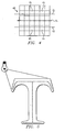
- FIGURE 4 illustrates a simple example of center-line based anti-aliasing in accordance with the invention.
- a line 40 which could be a portion of an alphanumeric character, has two opposing edges, E1 and E2.
- the center line, CL, between these edges is indicated as a dotted line.
- line 40 is superimposed over a grid of pixels, which will be printed (or not printed) to form the image.
- the pixels used to print the image either entirely overlap object 40, in which case they will be printed black, or they partly overlap, in which case they will be printed some shade of gray.
- a pair of “opposing” pixels is identified as P1 and P2. These pixels are “opposing” with respect to the center line 40 because they are both equidistant from the center line, CL.
- pixels P1 and P2 have less area covered by the line 40 that not covered.
- these two pixels would each be assigned a grayscale value less than mid-range.
- assigning each pixel such a value would have the perceived effect of narrowing the distance between them.
- line 40 would be perceived as being thinner at that point than its true shape.
- one of the pixels is assigned a higher intensity than the other.
- pixel P1 might be assigned a "black” intensity and pixel P2 a "white” intensity.
- Other "opposing" pixel-pairs, such as P3 and P4 would be identified and assigned values in a corresponding manner.
- P3 would also be black and P4 white. This would have the effect of eliminating aliasing, while at the same time, maintaining the true width of the line. The net effect is that the line is shifted upward.
- the invention can be used with any object that is described graphical description data, from which a center line can be calculated.
- a center line can be calculated or approximated.
- the opposing edges can be asymmetrical, such as are the edges at the curved portion of the T of FIGUREs 2 and 3.
- Compensating opposing pixels is only one example of adjusting the grayscale of two "opposing" pixels in accordance with the geometry of the object. Other adjustments could be made that would provide the optimum image quality in terms of both anti-aliasing and maintaining the true shape and position of the character.
- FIGURE 5 illustrates another use of center lines within a character, here a "T".
- the center lines are used to simulate embossed print. This is done by simulating a light source.
- the center lines identify the "top” of the character, with respect to the light source. Areas at the top of the character are highlighted.
- the center lines also delineate the "distant" sides of the character from the "close” sides with respect to the imaginary light source. This permits the distant sides to be printed darker than the close sides, with the grayscale varying with the distance from the light.
- the center line between two opposing edges can be used in other anti-aliasing algorithms.
- the direction of the center line could be monitored so that grayscale anti-aliasing is weighted in favor of diagonal lines rather than vertical or horizontal lines.
- the worst case aliasing occurs with lines at a 45 degree angle and such lines might be treated differently than lines at other angles.
- Grayscale anti-aliasing can also be used to smooth or accentuate changes in line width (the distance between two opposing edges).
- line width the distance between two opposing edges.
- the relationship between the direction of change and the direction of the center line could be monitored, and only changes along the direction of the center line might warrant insertion of gray pixels on the side of the character. This would avoid anti-aliasing on straight vertical and horizontal lines.
- Line-width can also be used independently of the center line, to improve anti-aliasing techniques.
- anti-aliasing decisions could be based on the rate of change of line width. Gradual changes might call for more grayscale antialiasing that abrupt changes.
- center line and line width data the common feature of using center line and line width data, is that the data can be used to make anti-aliasing decisions algorithmically, rather than on an ad hoc, per object, basis.
Landscapes
- Engineering & Computer Science (AREA)
- Physics & Mathematics (AREA)
- General Physics & Mathematics (AREA)
- Theoretical Computer Science (AREA)
- Optics & Photonics (AREA)
- General Engineering & Computer Science (AREA)
- Image Generation (AREA)
- Dot-Matrix Printers And Others (AREA)
- Facsimile Image Signal Circuits (AREA)
- Controls And Circuits For Display Device (AREA)
- Laser Beam Printer (AREA)
- Image Processing (AREA)
- Color, Gradation (AREA)
- Printers Or Recording Devices Using Electromagnetic And Radiation Means (AREA)
Applications Claiming Priority (2)
| Application Number | Priority Date | Filing Date | Title |
|---|---|---|---|
| US451895P | 1995-09-29 | 1995-09-29 | |
| US4518 | 1995-09-29 |
Publications (2)
| Publication Number | Publication Date |
|---|---|
| EP0766196A2 true EP0766196A2 (de) | 1997-04-02 |
| EP0766196A3 EP0766196A3 (de) | 1999-01-13 |
Family
ID=21711165
Family Applications (1)
| Application Number | Title | Priority Date | Filing Date |
|---|---|---|---|
| EP96115633A Withdrawn EP0766196A3 (de) | 1995-09-29 | 1996-09-30 | Mehrstufiger elektrographischer Druck |
Country Status (6)
| Country | Link |
|---|---|
| EP (1) | EP0766196A3 (de) |
| JP (1) | JPH09187992A (de) |
| KR (1) | KR970015031A (de) |
| CN (1) | CN1087842C (de) |
| CA (1) | CA2186053A1 (de) |
| TW (1) | TW330893B (de) |
Cited By (1)
| Publication number | Priority date | Publication date | Assignee | Title |
|---|---|---|---|---|
| EP1310906A1 (de) * | 2001-11-07 | 2003-05-14 | Eastman Kodak Company | Verfahren zur erhöhten Bittiefe in einem Bilderzeugungsgerät mit räumlichem Lichtmodulator |
Families Citing this family (1)
| Publication number | Priority date | Publication date | Assignee | Title |
|---|---|---|---|---|
| CN113674302B (zh) * | 2021-08-26 | 2024-03-05 | 中冶赛迪信息技术(重庆)有限公司 | 一种皮带机料面偏移识别方法、系统、电子设备及介质 |
Family Cites Families (6)
| Publication number | Priority date | Publication date | Assignee | Title |
|---|---|---|---|---|
| US4613945A (en) * | 1984-05-07 | 1986-09-23 | Pitney Bowes Inc. | Method and apparatus for creating fonts for an electronic character generator |
| JPS6165290A (ja) * | 1984-09-07 | 1986-04-03 | 株式会社日立製作所 | ベクトル文字フオントの作成装置 |
| US4851825A (en) * | 1987-07-24 | 1989-07-25 | Naiman Abraham C | Grayscale character generator and method |
| US5428692A (en) * | 1991-11-18 | 1995-06-27 | Kuehl; Eberhard | Character recognition system |
| JP3375638B2 (ja) * | 1993-06-10 | 2003-02-10 | アップル コンピュータ, インコーポレイテッド | アンチ−アライアジング装置及び目的グリッドへの水平・垂直エッジの自動高速合わせの方法 |
| US5453778A (en) * | 1993-07-30 | 1995-09-26 | Texas Instruments Incorporated | Method and apparatus for spatial modulation in the cross-process direction |
-
1996
- 1996-09-20 CA CA002186053A patent/CA2186053A1/en not_active Abandoned
- 1996-09-24 KR KR1019960041876A patent/KR970015031A/ko not_active Abandoned
- 1996-09-28 CN CN96122535A patent/CN1087842C/zh not_active Expired - Fee Related
- 1996-09-30 EP EP96115633A patent/EP0766196A3/de not_active Withdrawn
- 1996-09-30 JP JP25973896A patent/JPH09187992A/ja active Pending
- 1996-11-04 TW TW085113405A patent/TW330893B/zh active
Cited By (1)
| Publication number | Priority date | Publication date | Assignee | Title |
|---|---|---|---|---|
| EP1310906A1 (de) * | 2001-11-07 | 2003-05-14 | Eastman Kodak Company | Verfahren zur erhöhten Bittiefe in einem Bilderzeugungsgerät mit räumlichem Lichtmodulator |
Also Published As
| Publication number | Publication date |
|---|---|
| CN1162130A (zh) | 1997-10-15 |
| TW330893B (en) | 1998-05-01 |
| CA2186053A1 (en) | 1997-03-30 |
| JPH09187992A (ja) | 1997-07-22 |
| CN1087842C (zh) | 2002-07-17 |
| KR970015031A (ko) | 1997-04-28 |
| EP0766196A3 (de) | 1999-01-13 |
Similar Documents
| Publication | Publication Date | Title |
|---|---|---|
| JP3071229B2 (ja) | 図形処理装置 | |
| US5249242A (en) | Method for enhancing raster pixel data | |
| JP4045015B2 (ja) | ラスタ画像の解像度向上方法 | |
| JP6452504B2 (ja) | 画像形成装置、画像形成方法、プログラム | |
| JPH03154096A (ja) | パターン発生方法及びパターン発生装置 | |
| US6297889B1 (en) | Logic-based image processing method | |
| US5793936A (en) | Center-line anti-aliasing for digital printing | |
| US6342953B1 (en) | Color plane under exposure for reducing edge effect | |
| JP6833552B2 (ja) | 画像形成装置、画像形成方法、プログラム。 | |
| US6678426B1 (en) | Programmable mapping of lower resolution digital data to a higher resolution for output on a lower resolution device | |
| US20030026496A1 (en) | Smoothing method, smoothing circuit and image output apparatus | |
| US5841956A (en) | Anti-aliasing for digital printing with dot shape modulation and greyscale | |
| EP0766196A2 (de) | Mehrstufiger elektrographischer Druck | |
| US5786843A (en) | Two-dimensional modulation for line screen printing | |
| JP3811657B2 (ja) | 画像形成装置およびその調整方法 | |
| JP3942763B2 (ja) | ラスタ画像データのレンダリング方法 | |
| JP3793735B2 (ja) | 画像形成装置およびその調整方法 | |
| EP0932301B1 (de) | Steuerung der entwickelten Tonermenge unter Verwendung von Lasermodulationen von getrennten Unterelementen eines Bildes | |
| EP0785524A2 (de) | Druck mit Punktformmodulation und Grauwerten | |
| JPH04144479A (ja) | 図形出力装置 | |
| JP2798496B2 (ja) | 図形処理装置 | |
| KR100648657B1 (ko) | 클러스터를 통한 오차 확산장치 | |
| JPH1075367A (ja) | 画像形成装置 | |
| WO1995033330A1 (en) | Technique for rendering images on a binary marking engine | |
| JPH04249977A (ja) | 図形出力装置 |
Legal Events
| Date | Code | Title | Description |
|---|---|---|---|
| PUAI | Public reference made under article 153(3) epc to a published international application that has entered the european phase |
Free format text: ORIGINAL CODE: 0009012 |
|
| AK | Designated contracting states |
Kind code of ref document: A2 Designated state(s): DE FR GB IT NL |
|
| PUAL | Search report despatched |
Free format text: ORIGINAL CODE: 0009013 |
|
| AK | Designated contracting states |
Kind code of ref document: A3 Designated state(s): DE FR GB IT NL |
|
| 17P | Request for examination filed |
Effective date: 19990705 |
|
| 17Q | First examination report despatched |
Effective date: 20011115 |
|
| STAA | Information on the status of an ep patent application or granted ep patent |
Free format text: STATUS: THE APPLICATION IS DEEMED TO BE WITHDRAWN |
|
| 18D | Application deemed to be withdrawn |
Effective date: 20020326 |