EP0765963A1 - Automatic washer and tub therefor - Google Patents
Automatic washer and tub therefor Download PDFInfo
- Publication number
- EP0765963A1 EP0765963A1 EP96307004A EP96307004A EP0765963A1 EP 0765963 A1 EP0765963 A1 EP 0765963A1 EP 96307004 A EP96307004 A EP 96307004A EP 96307004 A EP96307004 A EP 96307004A EP 0765963 A1 EP0765963 A1 EP 0765963A1
- Authority
- EP
- European Patent Office
- Prior art keywords
- tub
- flange
- channel
- clothes washer
- automatic clothes
- Prior art date
- Legal status (The legal status is an assumption and is not a legal conclusion. Google has not performed a legal analysis and makes no representation as to the accuracy of the status listed.)
- Granted
Links
Images


Classifications
-
- D—TEXTILES; PAPER
- D06—TREATMENT OF TEXTILES OR THE LIKE; LAUNDERING; FLEXIBLE MATERIALS NOT OTHERWISE PROVIDED FOR
- D06F—LAUNDERING, DRYING, IRONING, PRESSING OR FOLDING TEXTILE ARTICLES
- D06F37/00—Details specific to washing machines covered by groups D06F21/00 - D06F25/00
- D06F37/26—Casings; Tubs
- D06F37/261—Tubs made by a specially selected manufacturing process or characterised by their assembly from elements
- D06F37/262—Tubs made by a specially selected manufacturing process or characterised by their assembly from elements made of plastic material, e.g. by injection moulding
-
- D—TEXTILES; PAPER
- D06—TREATMENT OF TEXTILES OR THE LIKE; LAUNDERING; FLEXIBLE MATERIALS NOT OTHERWISE PROVIDED FOR
- D06F—LAUNDERING, DRYING, IRONING, PRESSING OR FOLDING TEXTILE ARTICLES
- D06F37/00—Details specific to washing machines covered by groups D06F21/00 - D06F25/00
- D06F37/26—Casings; Tubs
- D06F37/261—Tubs made by a specially selected manufacturing process or characterised by their assembly from elements
- D06F37/263—Tubs made by a specially selected manufacturing process or characterised by their assembly from elements assembled from at least two elements connected to each other; Connecting or sealing means therefor
Definitions
- the invention relates to an automatic washer, and more specifically, to a tub for an automatic washer.
- Automatic clothes washers are generally vertical axis washers or horizontal axis washers. Both categories of washers have an imperforate tub in which a perforated wash basket is mounted for rotation relative to the tub. In the vertical axis washers, the basket rotates about a vertical axis. Likewise, in a horizontal axis washer, the basket rotates about a horizontal axis. Typically, horizontal axis automatic washers employ either a front-loading or a top-loading configuration for receiving clothes items to be washed.
- top-loading washers For these types of top-loading horizontal axis washers, it is known to form a tub from two pieces -- an upper tub member and a lower tub member.
- French Pat. No. 79,180 discloses a horizontal washer having a tub including an upper tub member and a lower tub member.
- the invention is directed to an automatic washer and a tub therefor in which the tub can be quickly and simply assembled and simultaneously accommodate variations in the dimensions of the tub members.
- the invention is directed to an automatic washer having a wash tub that defines a chamber adapted to receive a wash basket.
- the wash tub comprises an upper tub member and a lower tub member.
- the upper tub member has an upper peripheral rim.
- the lower tub member has a second peripheral rim.
- the upper and lower tub members are connected to form the tub by an interference connection between at least a portion of the upper and second peripheral rims.
- the upper peripheral rim is provided with opposing side walls connected by a transverse wall to define a U-shaped channel.
- the second peripheral rim is provided with a flange having opposing sides corresponding to the side walls of the upper peripheral rim.
- the channel and flange are sized accordingly so the flange can be received in the channel.
- a protrusion such as an integrally-formed rib, extends from at least one of the sides of the flange a sufficient distance to abut one of the side walls of the U-shaped channel, thereby providing an interference connection between the upper tub member and the lower tub member.
- the protrusions can be formed on the side walls of the U-shaped channel instead of the sides of the flange.
- the upper tub member and the lower tub member are preferably made from a resiliently flexible material so that when the flange abuts at least one of the side walls of the U-shaped channel, the flange is resiliently flexed, imparting a force against the side walls of the U-shaped channel, to form the interference connection between the upper tub member and the lower tub member.
- the upper and lower tub members are further secured together by a flexible tab having an engagement slot and provided on either the upper or lower tub member and an engagement hook corresponding to the flexible tab provided on the other of the upper tub member and lower tub member so that when the upper and lower tub members are connected by the interference connection, the engagement hook is received within the engagement slot, further securing the upper tub member to the lower tub member.
- the invention is a tub for an appliance -- the tub comprising an upper tub member having a pan-like body with a first peripheral rim and a lower tub member having a pan-like body with a second peripheral rim.
- the upper and lower tub members are connected together by an interference connection between at least a portion of the upper and second peripheral rims.
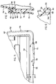
- FIG. 1 is a partially cut-away side elevational view of an automatic washer embodying the present invention.
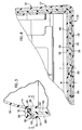
- FIG. 2 is a perspective view of a two-piece washer tub having an upper tub member and a lower tub member according to the present invention.
- FIG. 3 is a cross-sectional view of an interference connection between the upper tub member and the lower tub member taken along line 3-3 of FIG. 2.
- FIG. 4 is a partial sectional plan view, taken along line 4-4 of FIG. 3 of the interference connection between the upper tub member and the lower tub member.
- FIG. 5 is a bottom view of a portion of the upper tub member illustrating an alternative embodiment of the invention.
- FIG. 6 is a sectional view of the upper tub member taken along line 6-6 of FIG. 5.
- FIG. 7 is a sectional view of the interference connection between the upper tub member and the lower tub member taken along line 7-7 of FIG. 2.
- FIG. 1 there is illustrated a top-loading drum-type automatic washer 10 embodying the present invention.
- the washer 10 has an enclosure 12 including a top member 14, an outer cabinet 16 and an openable lid 18, shown in an open position, which encloses an imperforate wash tub 20.
- the top member 14 includes an access opening 22 extending partially along a top surface 12e and a front surface 12a for accessing the interior of the enclosure 12.
- the wash tub 20 has an upwardly-orientated rectangular tub opening 24.
- the opening 24 is aligned with the access opening 22 and a slidable wash tub lid 26, shown in an open position, is provided for sealably closing the opening 24.
- a rotatable, perforate wash basket 28 Disposed within the wash tub 20 is a rotatable, perforate wash basket 28 having a rectangular basket opening 30 provided with an openable first door flap 32 and an openable second door flap 34.
- the door flaps 32, 34 shown in an open position, may be aligned with the tub opening 24 to permit access into the wash basket 28 for the loading and unloading of clothes from the wash basket 28.
- the wash tub 20 is supported within the enclosure 12 by struts 36 extending from the tub 20 to a frame 38.
- a motor 40 is supported from the tub 20 and is drivably connected to a pulley 42 by a belt 44.
- the pulley 42 is drivably interconnected with the basket 28 such that the motor 40 can rotate the basket 28 within the tub.
- top-loading horizontal axis washer it is contemplated that the invention is also applicable to a top-loading or front-loading vertical axis or horizontal axis washer. It is also contemplated that the invention is applicable to appliances other than automatic washers, such as dishwashers.
- the tub 20 comprises an upper tub member 52 and a lower tub member 54, which are joined together by an interference connection 53.
- Both the upper tub member 52 and the lower tub member 54 are pan-shaped, having exterior walls 52a, 54a respectively, terminating in opposing end walls 52b, 54b, respectively.
- the rectangularly-shaped interference connection 53 can extend about the entire periphery of the upper and lower tub members 52, 54, including along a front edge 64a, back edge 64b, and side edges 64c and 64d. However, it is only necessary for the interference connection 53 to extend along at least a portion of the upper and lower tub members 52, 54, preferably, along opposing complementary sides of the upper and lower tub members.
- the upper tub member 52 includes a rectangularly-shaped bottom peripheral edge 55, which is formed by a first wall portion 56 and a second wall portion 58 connected by a transverse wall or bight portion 59.
- the downwardly-extending wall portions 56, 58 and the bight portion 59 define a downwardly-extending or inverted U-shaped channel 60.
- An elastomeric seal 65 is positioned within the channel 60 to fluidly seal the connection between the upper and lower tub members.
- the lower tub member 54 includes an upper peripheral edge 61 (FIG. 3), complementary in shape to the bottom peripheral edge 55 of the upper tub member 52, and has an upwardly-extending flange 62, which is received in the U-shaped channel.
- the U-shaped channel 60 and the flange 62 extend around the entire perimeter of the bottom peripheral edge 55 and the upper peripheral edge 61, respectively.
- ribs 66 are integrally formed with the lower tub member 54, extending from the flange 62 along the front and rear edge portions 64a and 64b.
- the ribs 66 are positioned in a spaced relationship and extend alternatingly from opposite sides of the flange 62.
- the ribs are illustrated on the front and rear edge portions, it is within the scope of the invention for the ribs to be positioned around the entire perimeter of the flange 62. However, it should be understood that the ribs only need extend along a portion of the flange 62 to perform their function.
- the upper tub member 52 and the lower tub member 54 are formed from a plastic material, such as filled polypropylene, which is resiliently flexible. As is well known by one skilled in the art of forming large plastic parts, size variations and warpage may occur.
- the present invention relates to a connection to join the tub members and accommodates any size variation and warpage when the upper and lower tub members are connected to form the tub.
- the width W of the U-shaped channel 60 is substantially greater than the thickness T of the flange 62 (FIG. 4).
- the width W of the U-shaped channel 60 is at least twice the thickness T of the flange 62.
- the inventors of the present invention contemplate that the width W of the U-shaped channel 60, at the front and rear edges 64a and 64b, is 10 mm and the thickness T of the flange 62 is 4 mm. In this fashion, regardless of the size variations or warpage, the flange 62 may be readily and easily received into the U-shaped channel 60.
- the upper tub member 52 and lower tub member 54 are joined by aligning the flange 62 and the channel 60 and inserting the flange 62 into the channel 60.
- the seal 65 is compressed between the flange 62 and the bight portion 59 to ensure a sealing relationship between the tub members.
- the ribs 66 extend 4 mm out from the flange 62.
- the ribs 66 cause the flange 62 to flex by alternatingly abutting opposite sides of the U-shaped channel 60.
- the flange 62 is distorted in a serpentine fashion whereby the upper tub member 52 and the lower tub member 54 are interferingly connected by the deflection of the flange 62 and the resiliency of the flange imparting a force against the side walls of the U-shaped channel.
- the extension of the ribs is sufficient to ensure that the flange is deflected while still maintaining a sufficient difference between the width of the channel and the thickness of the flange to permit the insertion of the flange within the channel while accommodating any variation in the dimensions of the upper and lower tub members.
- the ends of the ribs 66 are tapered to aid in their insertion within the channel.
- FlGs. 5 and 6 illustrate an alternate location for the ribs, which can be used alone or in combination with the ribs 66 shown in FIGS. 3 and 4.
- the alternate location places multiple ribs 68 within the U-shaped channel 60 along the front and rear edge portions 64a and 64b, instead of on the flange 62.
- the ribs 68 are positioned in a spaced relationship and extend alternatingly from the upper wall portion 56 and the lower wall portion 58 of the U-shaped channels illustrated, no ribs are provided extending from the flange; rather, the ribs 68, extending into the U-shaped channel, engage the flange and cause the flange to distort by alternatingly engaging opposite sides of the flange.
- the ribs 68 extend 4 mm into the U-shaped channel 60. In this fashion, the flange 62 is distorted in a serpentine fashion, in a manner similar to the upper embodiment.
- a plurality of flexible tabs 70 are provided downwardly extending from the first wall portion 56 of the bottom peripheral edge of the upper tub member 52. These tabs are provided along the front and rear edge portions 64a and 64b. Each of the flexible tabs 70 have an engagement slot 72.
- a plurality of engagement hooks 74 are provided outwardly extending from the lower tub member 54.
- the engagement hooks correspond in number and placement to the flexible tabs 70 such that when the upper tub member 52 and the lower tub member 54 are joined, the flexible tabs 70 and engagement hooks 74 align.
- the flexible tabs 70 are positioned to deflect over the engagement hooks 74 such that the engagement hooks 74 are captured in the engagement slots 72. In this fashion, the upper tub member 52 is securely connected to the lower tub member in a cost-effective manner without the need for any separate fasteners.
- the two-piece tub 20 overcomes the problem of dimensional variation associated with large molded plastic parts.
- the tub is further advantageous in that it is quickly and easily assembled without the need for special fasteners because of the interference connection.
- the automatic washer and tub according to the invention is a novel improvement over previous automatic washers and tubs.
Abstract
Description
- The invention relates to an automatic washer, and more specifically, to a tub for an automatic washer.
- Automatic clothes washers are generally vertical axis washers or horizontal axis washers. Both categories of washers have an imperforate tub in which a perforated wash basket is mounted for rotation relative to the tub. In the vertical axis washers, the basket rotates about a vertical axis. Likewise, in a horizontal axis washer, the basket rotates about a horizontal axis. Typically, horizontal axis automatic washers employ either a front-loading or a top-loading configuration for receiving clothes items to be washed. U.S. Pat. No. 3,197,980 to Marple, issued to the assignee of the present invention, shows a typical front-loading, horizontal axis washer wherein a horizontally oriented wash basket is accessed through one of the vertical end walls of the basket and the front surface of the washer.
- The preference of many consumers, however, particularly those in the United States, is for top-loading washers. For these types of top-loading horizontal axis washers, it is known to form a tub from two pieces -- an upper tub member and a lower tub member. French Pat. No. 79,180, for example, discloses a horizontal washer having a tub including an upper tub member and a lower tub member.
- As can be readily understood by one skilled in the art, it is desirable to have a connection between the tub members wherein their quick and economical joining is accomplished. The prior art suggests several systems for joining tub members. U.S. Pat. No. 3,060,764, issued October 30, 1962, discloses an inclined-axis washer having a two-piece metallic tub wherein the two pieces of the tub are secured together using a plurality of clamps. U.S. Pat. No. 2,807,963, issued October 1, 1957, discloses an inclined-axis washer having a two-piece metallic tub wherein a seal is provided between opposing radial flanges extending from the respective tub pieces and an annular, V-shaped band clamps together the tub pieces.
- One disadvantage of separate fasteners is that they increase the complexity and difficulty of assembling the tub. Also, as is well known, additional parts typically increase the cost of manufacturing. Another disadvantage of previous designs is that they do not provide for the simple positioning and alignment of the tub members relative to each other prior to securing together the tub members. Furthermore, as is well known by those skilled in the art, in the formation of large plastic parts, size variations and warpage may occur. These size variations and warpage must be accommodated when joining plastic tub members. The previous tub member connections do not address these problems. There exists, therefore, a need to easily and quickly secure tub members together in such a way to accommodate any dimensional variation and warpage in the tub members.
- The invention is directed to an automatic washer and a tub therefor in which the tub can be quickly and simply assembled and simultaneously accommodate variations in the dimensions of the tub members. In the preferred embodiment, the invention is directed to an automatic washer having a wash tub that defines a chamber adapted to receive a wash basket. The wash tub comprises an upper tub member and a lower tub member. The upper tub member has an upper peripheral rim. Likewise, the lower tub member has a second peripheral rim. The upper and lower tub members are connected to form the tub by an interference connection between at least a portion of the upper and second peripheral rims.
- Preferably, the upper peripheral rim is provided with opposing side walls connected by a transverse wall to define a U-shaped channel. The second peripheral rim is provided with a flange having opposing sides corresponding to the side walls of the upper peripheral rim. The channel and flange are sized accordingly so the flange can be received in the channel.
- A protrusion, such as an integrally-formed rib, extends from at least one of the sides of the flange a sufficient distance to abut one of the side walls of the U-shaped channel, thereby providing an interference connection between the upper tub member and the lower tub member. Preferably, there are multiple protrusions alternately disposed on the opposing sides of the flange. Alternatively, the protrusions can be formed on the side walls of the U-shaped channel instead of the sides of the flange.
- The upper tub member and the lower tub member are preferably made from a resiliently flexible material so that when the flange abuts at least one of the side walls of the U-shaped channel, the flange is resiliently flexed, imparting a force against the side walls of the U-shaped channel, to form the interference connection between the upper tub member and the lower tub member. The upper and lower tub members are further secured together by a flexible tab having an engagement slot and provided on either the upper or lower tub member and an engagement hook corresponding to the flexible tab provided on the other of the upper tub member and lower tub member so that when the upper and lower tub members are connected by the interference connection, the engagement hook is received within the engagement slot, further securing the upper tub member to the lower tub member.
- In another embodiment, the invention is a tub for an appliance -- the tub comprising an upper tub member having a pan-like body with a first peripheral rim and a lower tub member having a pan-like body with a second peripheral rim. The upper and lower tub members are connected together by an interference connection between at least a portion of the upper and second peripheral rims.
- FIG. 1 is a partially cut-away side elevational view of an automatic washer embodying the present invention.
- FIG. 2 is a perspective view of a two-piece washer tub having an upper tub member and a lower tub member according to the present invention.
- FIG. 3 is a cross-sectional view of an interference connection between the upper tub member and the lower tub member taken along line 3-3 of FIG. 2.
- FIG. 4 is a partial sectional plan view, taken along line 4-4 of FIG. 3 of the interference connection between the upper tub member and the lower tub member.
- FIG. 5 is a bottom view of a portion of the upper tub member illustrating an alternative embodiment of the invention.
- FIG. 6 is a sectional view of the upper tub member taken along line 6-6 of FIG. 5.
- FIG. 7 is a sectional view of the interference connection between the upper tub member and the lower tub member taken along line 7-7 of FIG. 2.
- Referring to the drawings and specifically to FIG. 1, there is illustrated a top-loading drum-type
automatic washer 10 embodying the present invention. Thewasher 10 has anenclosure 12 including atop member 14, anouter cabinet 16 and anopenable lid 18, shown in an open position, which encloses animperforate wash tub 20. Thetop member 14 includes an access opening 22 extending partially along a top surface 12e and afront surface 12a for accessing the interior of theenclosure 12. - The
wash tub 20 has an upwardly-orientated rectangular tub opening 24. The opening 24 is aligned with the access opening 22 and a slidablewash tub lid 26, shown in an open position, is provided for sealably closing the opening 24. - Disposed within the
wash tub 20 is a rotatable,perforate wash basket 28 having a rectangular basket opening 30 provided with an openablefirst door flap 32 and an openablesecond door flap 34. Thedoor flaps wash basket 28 for the loading and unloading of clothes from thewash basket 28. - The
wash tub 20 is supported within theenclosure 12 bystruts 36 extending from thetub 20 to aframe 38. A motor 40 is supported from thetub 20 and is drivably connected to apulley 42 by abelt 44. Thepulley 42 is drivably interconnected with thebasket 28 such that the motor 40 can rotate thebasket 28 within the tub. - The specific structure of the wash basket, enclosure and various control systems for the
washer 10 are shown and described in European Patent Application Serial No. 95302955.0, which is incorporated by reference. - It should be noted that although the invention is illustrated in the context of a top-loading horizontal axis washer, it is contemplated that the invention is also applicable to a top-loading or front-loading vertical axis or horizontal axis washer. It is also contemplated that the invention is applicable to appliances other than automatic washers, such as dishwashers.
- Turning to FlGs. 2-4, various features of the
tub 20 are shown in greater detail. Thetub 20 comprises anupper tub member 52 and alower tub member 54, which are joined together by aninterference connection 53. Both theupper tub member 52 and thelower tub member 54 are pan-shaped, havingexterior walls end walls interference connection 53 can extend about the entire periphery of the upper andlower tub members front edge 64a, backedge 64b, andside edges interference connection 53 to extend along at least a portion of the upper andlower tub members - The
upper tub member 52 includes a rectangularly-shaped bottomperipheral edge 55, which is formed by afirst wall portion 56 and asecond wall portion 58 connected by a transverse wall orbight portion 59. The downwardly-extendingwall portions bight portion 59, define a downwardly-extending or invertedU-shaped channel 60. Anelastomeric seal 65 is positioned within thechannel 60 to fluidly seal the connection between the upper and lower tub members. - The
lower tub member 54 includes an upper peripheral edge 61 (FIG. 3), complementary in shape to the bottomperipheral edge 55 of theupper tub member 52, and has an upwardly-extendingflange 62, which is received in the U-shaped channel. Preferably, theU-shaped channel 60 and theflange 62 extend around the entire perimeter of the bottomperipheral edge 55 and the upperperipheral edge 61, respectively. - Multiple protrusions or
ribs 66 are integrally formed with thelower tub member 54, extending from theflange 62 along the front andrear edge portions ribs 66 are positioned in a spaced relationship and extend alternatingly from opposite sides of theflange 62. Although the ribs are illustrated on the front and rear edge portions, it is within the scope of the invention for the ribs to be positioned around the entire perimeter of theflange 62. However, it should be understood that the ribs only need extend along a portion of theflange 62 to perform their function. - As contemplated by the inventors, the
upper tub member 52 and thelower tub member 54 are formed from a plastic material, such as filled polypropylene, which is resiliently flexible. As is well known by one skilled in the art of forming large plastic parts, size variations and warpage may occur. The present invention relates to a connection to join the tub members and accommodates any size variation and warpage when the upper and lower tub members are connected to form the tub. - To provide clearance to accommodate the above-described potential size variations and part warpage, the width W of the
U-shaped channel 60 is substantially greater than the thickness T of the flange 62 (FIG. 4). Preferably, the width W of theU-shaped channel 60 is at least twice the thickness T of theflange 62. Specifically, the inventors of the present invention contemplate that the width W of theU-shaped channel 60, at the front andrear edges flange 62 is 4 mm. In this fashion, regardless of the size variations or warpage, theflange 62 may be readily and easily received into theU-shaped channel 60. - A brief description of the joining of the upper and lower tub members will aid in the understanding of the tub and its connection. The
upper tub member 52 andlower tub member 54 are joined by aligning theflange 62 and thechannel 60 and inserting theflange 62 into thechannel 60. Theseal 65 is compressed between theflange 62 and thebight portion 59 to ensure a sealing relationship between the tub members. - Preferably, the
ribs 66 extend 4 mm out from theflange 62. As shown in FIG. 4, when theflange 62 is positioned within theU-shaped channel 60, theribs 66 cause theflange 62 to flex by alternatingly abutting opposite sides of theU-shaped channel 60. In this fashion, theflange 62 is distorted in a serpentine fashion whereby theupper tub member 52 and thelower tub member 54 are interferingly connected by the deflection of theflange 62 and the resiliency of the flange imparting a force against the side walls of the U-shaped channel. The extension of the ribs is sufficient to ensure that the flange is deflected while still maintaining a sufficient difference between the width of the channel and the thickness of the flange to permit the insertion of the flange within the channel while accommodating any variation in the dimensions of the upper and lower tub members. The ends of theribs 66 are tapered to aid in their insertion within the channel. - FlGs. 5 and 6 illustrate an alternate location for the ribs, which can be used alone or in combination with the
ribs 66 shown in FIGS. 3 and 4. The alternate location placesmultiple ribs 68 within theU-shaped channel 60 along the front andrear edge portions flange 62. Theribs 68 are positioned in a spaced relationship and extend alternatingly from theupper wall portion 56 and thelower wall portion 58 of the U-shaped channels illustrated, no ribs are provided extending from the flange; rather, theribs 68, extending into the U-shaped channel, engage the flange and cause the flange to distort by alternatingly engaging opposite sides of the flange. Preferably, theribs 68 extend 4 mm into theU-shaped channel 60. In this fashion, theflange 62 is distorted in a serpentine fashion, in a manner similar to the upper embodiment. - Referring to FlGs. 2 and 7, the system for securing the
upper tub 52 to thelower tub 54 may be described. A plurality offlexible tabs 70 are provided downwardly extending from thefirst wall portion 56 of the bottom peripheral edge of theupper tub member 52. These tabs are provided along the front andrear edge portions flexible tabs 70 have anengagement slot 72. - A plurality of engagement hooks 74 are provided outwardly extending from the
lower tub member 54. The engagement hooks correspond in number and placement to theflexible tabs 70 such that when theupper tub member 52 and thelower tub member 54 are joined, theflexible tabs 70 and engagement hooks 74 align. Moreover, when theflange 62 is received into theU-shaped channel 60, theflexible tabs 70 are positioned to deflect over the engagement hooks 74 such that the engagement hooks 74 are captured in theengagement slots 72. In this fashion, theupper tub member 52 is securely connected to the lower tub member in a cost-effective manner without the need for any separate fasteners. - The two-
piece tub 20 overcomes the problem of dimensional variation associated with large molded plastic parts. The tub is further advantageous in that it is quickly and easily assembled without the need for special fasteners because of the interference connection. Overall, the automatic washer and tub according to the invention is a novel improvement over previous automatic washers and tubs. - Although the present invention has been described with reference to specific embodiments, those of skill in the art will recognize that changes may be made thereto without departing from the scope and spirit of the invention as set forth in the appended claims.
Claims (12)
- An automatic clothes washer comprising a wash tub (20) defining a chamber adapted to receive a wash basket (28) and the wash tub having an upper tub member (52) with a first peripheral rim (55) and a lower tub member (54) with a second peripheral rim (61); characterised in that an interference connection (56,58,62,66) is provided between at least a portion of the first and second peripheral rims to secure together the upper and lower tub members to form the tub.
- An automatic clothes washer according to claim 1, characterised in that opposing side walls (56,58) are provided on the first peripheral rim to form a channel, in that a flange (61) having opposing sides corresponding to the side walls is provided on the second peripheral rim, the channel and flange being sized so that the flange can be received in the channel, and at least a portion of the flange (61) and at least a portion of at least one of the side walls (56,58) abutting when the flange is received in the channel to form the interference connection.
- An automatic clothes washer according to claim 2, characterised in that the first peripheral rim is further provided with a transverse flange (59) extending between the side walls (56,58) to form a U-shaped channel.
- An automatic clothes washer according to claim 2 or 3, characterised in that the flange (61) is resiliently flexible whereby when the flange abuts a side wall (56,58) the flange is flexed to form the interference connection.
- An automatic clothes washer according to claim 2, 3 or 4, characterised in that at least one of the opposing side walls (56,58) comprises at least one protrusion (66) extending a sufficient distance to abut one of the side walls when the flange is received in the channel to form the interference connection.
- An automatic clothes washer according to claim 5, characterised in that multiple protrusions (66) extend from the opposing sides, alternating between the opposing side walls (56,58).
- An automatic clothes washer according to claim 6, characterised in that the protrusions are ribs (66) integrally formed with the opposing side walls (56,58).
- An automatic clothes washer according to any one of claims 2 to 7, characterised in that at least one of the side walls (56,58) comprises at least one protrusion (66) extending a sufficient distance to abut one of the sides when the flange is received in the channel to form the interference connection.
- An automatic clothes washer according to any one of claims 2 to 8, characterised in that the first peripheral rim is generally rectangular having opposing elongated portions (52a) and opposing end portions (52b) and the channel is provided on one of the elongated portions and end portions; and the second peripheral rim having opposing elongated portions (54a) and opposing end portions (54b) corresponding to the elongated portions and end portions of the first peripheral rim and the flange is provided on the one of the elongated portions and end portions of first peripheral corresponding to the one of the elongated portions and end portions on which the channel is provided.
- An automatic clothes washer according to any one of claims 2 to 9, characterised in that the width of the channel is at least twice the thickness of the flange so that the flange can be received in the channel.
- An automatic clothes washer according to any one of claims 2 to 10, characterised in that a seal (65) is positioned in the channel to fluidly seal the upper tub member relative to the lower tub member when the upper and lower tub members are connected.
- An automatic clothes washer according to any preceding claim, characterised in that one of the upper tub member and lower tub member has at least one flexible tab (70) with an engagement slot (72) and the other of the upper tub member and the lower tub member has at least one engagement hook (74) corresponding to the flexible tab and aligned with and extending through the engagement slot when the upper and lower tub members are connected by the interference connection to further secure together the upper and lower tub members.
Applications Claiming Priority (2)
| Application Number | Priority Date | Filing Date | Title |
|---|---|---|---|
| US454495P | 1995-09-29 | 1995-09-29 | |
| US4544 | 1995-09-29 |
Publications (2)
| Publication Number | Publication Date |
|---|---|
| EP0765963A1 true EP0765963A1 (en) | 1997-04-02 |
| EP0765963B1 EP0765963B1 (en) | 2001-04-11 |
Family
ID=21711304
Family Applications (1)
| Application Number | Title | Priority Date | Filing Date |
|---|---|---|---|
| EP96307004A Expired - Lifetime EP0765963B1 (en) | 1995-09-29 | 1996-09-26 | Automatic washer and tub therefor |
Country Status (4)
| Country | Link |
|---|---|
| US (1) | US5852942A (en) |
| EP (1) | EP0765963B1 (en) |
| DE (1) | DE69612444T2 (en) |
| ES (1) | ES2155579T3 (en) |
Cited By (4)
| Publication number | Priority date | Publication date | Assignee | Title |
|---|---|---|---|---|
| EP3176303A1 (en) * | 2015-12-01 | 2017-06-07 | Whirlpool Corporation | Laundry treating appliance |
| US10036114B2 (en) | 2015-12-01 | 2018-07-31 | Whirlpool Corporation | Laundry treating appliance |
| US10125446B2 (en) | 2015-12-01 | 2018-11-13 | Whirlpool Corporation | Laundry treating appliance |
| US10487432B2 (en) | 2015-12-01 | 2019-11-26 | Whirlpool Corporation | Laundry treating appliance |
Families Citing this family (7)
| Publication number | Priority date | Publication date | Assignee | Title |
|---|---|---|---|---|
| US6045588A (en) | 1997-04-29 | 2000-04-04 | Whirlpool Corporation | Non-aqueous washing apparatus and method |
| US7695524B2 (en) * | 2003-10-31 | 2010-04-13 | Whirlpool Corporation | Non-aqueous washing machine and methods |
| WO2005106105A1 (en) | 2004-04-29 | 2005-11-10 | Unilever N.V. | Dry cleaning method |
| US7966684B2 (en) | 2005-05-23 | 2011-06-28 | Whirlpool Corporation | Methods and apparatus to accelerate the drying of aqueous working fluids |
| US20100037923A1 (en) * | 2008-08-14 | 2010-02-18 | Whirlpool Corporation | Removable dishwasher filtration system |
| KR101584546B1 (en) * | 2009-01-06 | 2016-01-22 | 엘지전자 주식회사 | Washing mahcine |
| CA2998155C (en) * | 2015-09-18 | 2022-10-25 | Hida Hasinovic | Cleaning composition and method of cleaning air intake valve deposits |
Citations (4)
| Publication number | Priority date | Publication date | Assignee | Title |
|---|---|---|---|---|
| DE1610072A1 (en) * | 1966-08-17 | 1971-04-01 | Siemens Elektrogeraete Gmbh | Laundry machine designed for washing and spinning |
| DE2507849A1 (en) * | 1975-02-24 | 1976-09-02 | Blomberg Werke Kg | Washing machine with spring-mounted tub - with simple space-saving inertia mass for vibrating unit |
| FR2564492A1 (en) * | 1984-05-16 | 1985-11-22 | Bosch Siemens Hausgeraete | Washing machine filler |
| DE4235003A1 (en) * | 1991-10-16 | 1993-04-22 | Samsung Electronics Co Ltd | WASHING MACHINE FOR WASHING LAUNDRY WITH BOILING WATER |
Family Cites Families (11)
| Publication number | Priority date | Publication date | Assignee | Title |
|---|---|---|---|---|
| US2083503A (en) * | 1935-05-21 | 1937-06-08 | Easy Washing Machine Corp | Washing machine construction |
| US2309617A (en) * | 1938-04-14 | 1943-01-26 | Chicago Electric Mfg Co | Washing machine |
| US2631447A (en) * | 1949-03-18 | 1953-03-17 | Eilersgaard Asger | Washing machine provided with detergent lubricating means |
| US2807963A (en) * | 1954-03-31 | 1957-10-01 | Westinghouse Electric Corp | Multiple speed transmission |
| US2968174A (en) * | 1956-11-06 | 1961-01-17 | Hoover Co | Washing machines |
| GB881271A (en) * | 1958-12-12 | 1961-11-01 | Gen Motors France | Improvements in clothes washing machines |
| GB972279A (en) * | 1960-05-12 | 1964-10-14 | Hoover Ltd | Improvements relating to washing machines |
| BR7501017A (en) * | 1974-03-01 | 1975-12-02 | Ite Imperial Corp | CIRCUIT PROTECTIVE DEVICE |
| US5050754A (en) * | 1989-10-23 | 1991-09-24 | West Penn Plastics, Inc. | Cap for a neck finish on a wide mouth container |
| US5711170A (en) * | 1994-08-19 | 1998-01-27 | Maytag Corporation | Integrated tub and cabinet structure |
| US5570598A (en) * | 1995-02-21 | 1996-11-05 | Haven; Lonnie M. | Counter top clothes washer |
-
1996
- 1996-09-04 US US08/707,789 patent/US5852942A/en not_active Expired - Fee Related
- 1996-09-26 EP EP96307004A patent/EP0765963B1/en not_active Expired - Lifetime
- 1996-09-26 ES ES96307004T patent/ES2155579T3/en not_active Expired - Lifetime
- 1996-09-26 DE DE69612444T patent/DE69612444T2/en not_active Expired - Lifetime
Patent Citations (4)
| Publication number | Priority date | Publication date | Assignee | Title |
|---|---|---|---|---|
| DE1610072A1 (en) * | 1966-08-17 | 1971-04-01 | Siemens Elektrogeraete Gmbh | Laundry machine designed for washing and spinning |
| DE2507849A1 (en) * | 1975-02-24 | 1976-09-02 | Blomberg Werke Kg | Washing machine with spring-mounted tub - with simple space-saving inertia mass for vibrating unit |
| FR2564492A1 (en) * | 1984-05-16 | 1985-11-22 | Bosch Siemens Hausgeraete | Washing machine filler |
| DE4235003A1 (en) * | 1991-10-16 | 1993-04-22 | Samsung Electronics Co Ltd | WASHING MACHINE FOR WASHING LAUNDRY WITH BOILING WATER |
Cited By (6)
| Publication number | Priority date | Publication date | Assignee | Title |
|---|---|---|---|---|
| EP3176303A1 (en) * | 2015-12-01 | 2017-06-07 | Whirlpool Corporation | Laundry treating appliance |
| US10036114B2 (en) | 2015-12-01 | 2018-07-31 | Whirlpool Corporation | Laundry treating appliance |
| US10053808B2 (en) | 2015-12-01 | 2018-08-21 | Whirlpool Corporation | Laundry treating appliance |
| US10125446B2 (en) | 2015-12-01 | 2018-11-13 | Whirlpool Corporation | Laundry treating appliance |
| US10487432B2 (en) | 2015-12-01 | 2019-11-26 | Whirlpool Corporation | Laundry treating appliance |
| US11236458B2 (en) | 2015-12-01 | 2022-02-01 | Whirlpool Corporation | Laundry treating appliance |
Also Published As
| Publication number | Publication date |
|---|---|
| US5852942A (en) | 1998-12-29 |
| EP0765963B1 (en) | 2001-04-11 |
| DE69612444T2 (en) | 2001-07-26 |
| DE69612444D1 (en) | 2001-05-17 |
| ES2155579T3 (en) | 2001-05-16 |
Similar Documents
| Publication | Publication Date | Title |
|---|---|---|
| US5852942A (en) | Automatic washer and tub therefor | |
| EP1507034A2 (en) | Appliance doors | |
| EP1319100B1 (en) | Laundry appliance | |
| US7320186B2 (en) | Appliance door having see-through portion | |
| US5678430A (en) | Tub door system for a top loading horizontal axis automatic washer | |
| AU2001279956A1 (en) | Laundry appliance | |
| US5989418A (en) | Filter for a washing machine | |
| US20050262887A1 (en) | Door assembly for washing machine | |
| CA2168606A1 (en) | Appliance top assembly | |
| US4366902A (en) | Shipping system for automatic washer | |
| US20040231370A1 (en) | Washing machine lid | |
| US20040107738A1 (en) | Washing machine and cabinet thereof | |
| EP2785907B1 (en) | Household electrical appliance and loading door for such appliance | |
| US4572596A (en) | Method and apparatus for assembling a cabinet for automatic washers | |
| US5611610A (en) | Control housing | |
| US5765404A (en) | Balance ring attachment in an automatic washer | |
| US20060290247A1 (en) | Assembly structure of a washing machine's console and assembly method | |
| US5066050A (en) | Dryer transition duct | |
| KR100484830B1 (en) | Drum washing machine | |
| GB2072059A (en) | Domestic appliance cabinet | |
| JP3063478B2 (en) | Washing and dewatering tub | |
| EP0672778A1 (en) | Washing machine | |
| KR20180136142A (en) | Wall mounted drum type washing machine | |
| US3581527A (en) | Laundry machine structure | |
| WO2002022934A2 (en) | Laundry appliance |
Legal Events
| Date | Code | Title | Description |
|---|---|---|---|
| PUAI | Public reference made under article 153(3) epc to a published international application that has entered the european phase |
Free format text: ORIGINAL CODE: 0009012 |
|
| AK | Designated contracting states |
Kind code of ref document: A1 Designated state(s): DE ES FR GB IT |
|
| 17P | Request for examination filed |
Effective date: 19971001 |
|
| 17Q | First examination report despatched |
Effective date: 19990331 |
|
| GRAG | Despatch of communication of intention to grant |
Free format text: ORIGINAL CODE: EPIDOS AGRA |
|
| GRAG | Despatch of communication of intention to grant |
Free format text: ORIGINAL CODE: EPIDOS AGRA |
|
| GRAH | Despatch of communication of intention to grant a patent |
Free format text: ORIGINAL CODE: EPIDOS IGRA |
|
| ITF | It: translation for a ep patent filed |
Owner name: JACOBACCI & PERANI S.P.A. |
|
| GRAH | Despatch of communication of intention to grant a patent |
Free format text: ORIGINAL CODE: EPIDOS IGRA |
|
| GRAA | (expected) grant |
Free format text: ORIGINAL CODE: 0009210 |
|
| AK | Designated contracting states |
Kind code of ref document: B1 Designated state(s): DE ES FR GB IT |
|
| REG | Reference to a national code |
Ref country code: ES Ref legal event code: FG2A Ref document number: 2155579 Country of ref document: ES Kind code of ref document: T3 |
|
| REF | Corresponds to: |
Ref document number: 69612444 Country of ref document: DE Date of ref document: 20010517 |
|
| ET | Fr: translation filed | ||
| REG | Reference to a national code |
Ref country code: GB Ref legal event code: IF02 |
|
| PLBE | No opposition filed within time limit |
Free format text: ORIGINAL CODE: 0009261 |
|
| STAA | Information on the status of an ep patent application or granted ep patent |
Free format text: STATUS: NO OPPOSITION FILED WITHIN TIME LIMIT |
|
| 26N | No opposition filed | ||
| REG | Reference to a national code |
Ref country code: FR Ref legal event code: PLFP Year of fee payment: 20 |
|
| PGFP | Annual fee paid to national office [announced via postgrant information from national office to epo] |
Ref country code: ES Payment date: 20150810 Year of fee payment: 20 Ref country code: GB Payment date: 20150923 Year of fee payment: 20 Ref country code: DE Payment date: 20150922 Year of fee payment: 20 |
|
| PGFP | Annual fee paid to national office [announced via postgrant information from national office to epo] |
Ref country code: FR Payment date: 20150629 Year of fee payment: 20 |
|
| PGFP | Annual fee paid to national office [announced via postgrant information from national office to epo] |
Ref country code: IT Payment date: 20150925 Year of fee payment: 20 |
|
| REG | Reference to a national code |
Ref country code: DE Ref legal event code: R071 Ref document number: 69612444 Country of ref document: DE |
|
| REG | Reference to a national code |
Ref country code: GB Ref legal event code: PE20 Expiry date: 20160925 |
|
| PG25 | Lapsed in a contracting state [announced via postgrant information from national office to epo] |
Ref country code: GB Free format text: LAPSE BECAUSE OF EXPIRATION OF PROTECTION Effective date: 20160925 |
|
| REG | Reference to a national code |
Ref country code: ES Ref legal event code: FD2A Effective date: 20170102 |
|
| PG25 | Lapsed in a contracting state [announced via postgrant information from national office to epo] |
Ref country code: ES Free format text: LAPSE BECAUSE OF EXPIRATION OF PROTECTION Effective date: 20160927 |