EP0765770B1 - Coupling device between a truck and a trailer with control of path movement of trailer - Google Patents
Coupling device between a truck and a trailer with control of path movement of trailer Download PDFInfo
- Publication number
- EP0765770B1 EP0765770B1 EP96440075A EP96440075A EP0765770B1 EP 0765770 B1 EP0765770 B1 EP 0765770B1 EP 96440075 A EP96440075 A EP 96440075A EP 96440075 A EP96440075 A EP 96440075A EP 0765770 B1 EP0765770 B1 EP 0765770B1
- Authority
- EP
- European Patent Office
- Prior art keywords
- trailer
- drawbar
- truck
- coupling gear
- mechanical coupling
- Prior art date
- Legal status (The legal status is an assumption and is not a legal conclusion. Google has not performed a legal analysis and makes no representation as to the accuracy of the status listed.)
- Expired - Lifetime
Links
- 230000008878 coupling Effects 0.000 title claims abstract description 29
- 238000010168 coupling process Methods 0.000 title claims abstract description 29
- 238000005859 coupling reaction Methods 0.000 title claims abstract description 29
- 230000014759 maintenance of location Effects 0.000 claims 1
- 241000946381 Timon Species 0.000 description 9
- 238000010586 diagram Methods 0.000 description 6
- 230000000694 effects Effects 0.000 description 3
- 230000001681 protective effect Effects 0.000 description 3
- 239000002131 composite material Substances 0.000 description 2
- 239000000463 material Substances 0.000 description 2
- 238000005096 rolling process Methods 0.000 description 2
- 241001236644 Lavinia Species 0.000 description 1
- 230000001133 acceleration Effects 0.000 description 1
- 239000011324 bead Substances 0.000 description 1
- 239000000969 carrier Substances 0.000 description 1
- 238000010276 construction Methods 0.000 description 1
- 238000013016 damping Methods 0.000 description 1
- 210000000887 face Anatomy 0.000 description 1
- 239000012530 fluid Substances 0.000 description 1
- 210000001061 forehead Anatomy 0.000 description 1
- 210000003128 head Anatomy 0.000 description 1
- 239000011229 interlayer Substances 0.000 description 1
- 239000010410 layer Substances 0.000 description 1
Images


Classifications
-
- B—PERFORMING OPERATIONS; TRANSPORTING
- B60—VEHICLES IN GENERAL
- B60D—VEHICLE CONNECTIONS
- B60D1/00—Traction couplings; Hitches; Draw-gear; Towing devices
- B60D1/14—Draw-gear or towing devices characterised by their type
- B60D1/173—Draw-gear or towing devices characterised by their type consisting of at least two bars which are not connected or articulated to each other
-
- B—PERFORMING OPERATIONS; TRANSPORTING
- B60—VEHICLES IN GENERAL
- B60D—VEHICLE CONNECTIONS
- B60D1/00—Traction couplings; Hitches; Draw-gear; Towing devices
- B60D1/14—Draw-gear or towing devices characterised by their type
- B60D1/145—Draw-gear or towing devices characterised by their type consisting of an elongated single bar or tube
- B60D1/155—Draw-gear or towing devices characterised by their type consisting of an elongated single bar or tube comprising telescopic or foldable parts
Definitions
- the present invention relates to a mechanical coupling between a truck and a trailer, control of the trajectory of the trailer, in accordance with the characteristics of the preamble of claim 1.
- the mechanical coupling according to the invention is formed of a drawbar and at least one oblique connection, rigid, articulated by one of its ends to the trailer and by its other end to the truck.
- the road hitches provide the trailer with clearing trajectory so that it is in a better position in turns and out of curves in order to better follow the road lane which is assigned to the truck-trailer combination.
- This hitch consists of a drawbar and an oblique link articulated on a train interface before director.
- the drawbar is hinged mounted at its front end on the hook towing the truck and at its rear end on the round front end conventionally constituting the interface between the front axle and the hitch.
- the axle front is fixed.
- An intermediate control unit ensures the directional orientation of the front wheels from the direction of the pulling force exerted on the drawbar.
- This invention uses a drawbar, an oblique rod, a control interface and the train front of a trailer known as a steering front axle.
- the oblique connecting rod provides a trajectory cornering cornerer of the trailer on which it is articulated away from the corresponding rear corner of the truck.
- the drawbar does not transmit a significant load to the towing vehicle because the weight of the front part is supported by the steering front axle.
- This coupling is specific to a train trailer before director.
- the object of the present invention is to provide a center axle trailer with these characteristics and ensures a clear path at the corner of the trailer.
- the object of the present invention is to arrive at this result with simple means only mechanical i.e. a drawbar of constant length or a passive and free telescopic drawbar in extension-retraction, that is to say not recalled under the effect of a fluid or the like and one or two oblique rod (s) rigid (s), of constant length, articulated on the trailer and on the truck.
- the invention also aims with a hitch simple mechanics to give the trailer a clearing path which allows the transport of loads protruding from the front of the trailer and / or the back of the truck.
- the invention proposes to achieve these results more specifically with a coupling conforming to the characteristics of claim 1.
- a mechanical coupling formed on the one hand by a drawbar whose front end is hooked at the rear, for example overhanging the truck, and whose the rear end is part of a center of pivoting around a substantially vertical axis mounted on the trailer chassis and on the other hand at minus a connecting rod oblique to the direction of straight line, rigid rod and constant length, articulated climb by one of its ends on the back of the truck and by its other end to the rear of the trailer.
- the link formed by a single oblique link is doubled by a second oblique rod to transform into a link with crossed connecting rods arranged in straight line configuration, along diagonals in the space between the truck and the trailer.
- This invention in its application short hitch brings several advantages additional important including the possibility with a reduced truck-trailer space to place loads indivisible cantilevered and projecting nested from the back of the truck and / or the front of the trailer.
- the present invention relates to a mechanical coupling between a motor vehicle, called here for the sake of simplification truck 1, and a trailer 2.
- Trailer 2 is shown as a center axle trailer 3 and 4 and will be described Such as.
- Truck 1 has a cab 5 and a chassis 6, the latter being surmounted by a bodywork 7 fixed or removable.
- This bodywork is provided by example, but not necessarily, for transporting cars on platforms or platforms individual loading.
- trailer which includes a frame 8 on which is mounted for example a bodywork for 9 car carriers with platforms or individual loading platforms.
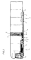
- the vehicles, truck and trailer delimit between them an intermediate space for connecting 10 truck-trailer, for example protected by a bellows 11, as shown in Figures 1 and 2.
- the present invention relates to binding between truck and trailer forming a mechanical coupling 12 to control the trajectory of the trailer formed a pivoting drawbar and at least one oblique connection relative to the straight line direction.
- FIGS 1 and 2 show the whole trailer truck with any swivel drawbar 13.
- this pivoting drawbar can be rigid and of constant length in a first mode of realization with a single oblique connection or free and passive telescopic in a second form of double oblique connection.
- the pivoting drawbar 13 has on the one hand a front end 14 connected to a coupling point 15 with hook carried by a transverse mechanical assembly 16 secured to the truck chassis 6 or the bodywork having for example an extension rear cantilever and on the other end rear 17 forming part or constituting one of the parts a pivot center 18 mounted in cantilever at the front of the trailer chassis 8 or in the vicinity of this one.
- the swivel drawbar 13 is a rigid swivel drawbar 19 pivoting around the pivot center 18.
- This drawbar is of constant length L and the oblique bond is constituted by a rigid rod 20 of length D constant. It crosses obliquely the plane longitudinal center line of the vehicle according to a diagonal arrangement and is articulated by its ends level, for example from a rear corner 21 or 22 of the truck and a front corner 23 or 24 of the trailer.
- the center of pivot 18 is made in the form of a round front end 25 mounted in cantilever at the front of the trailer chassis 8.
- a second variant of the first form of realization implements a pivot center 18 equivalent to the front end of the first variant which therefore provides the same effects.
- the round front end 25 is replaced by a pivoting axle end 26 mounted vertically under the chassis 8 trailer in the middle position and perpendicular to it frame.
- the whole is completed by a means of link-support 27 of the trailer at the front.
- link-support 27 consists in the example represented in a track 28 in an arc and in a sliding support on this track on a range area 29 formed by the surface of the drawbar opposite the track 28 in an arc completed with a sliding connection 30 between the drawbar and the structure of the track 28 in an arc.
- This link allows maintain the front part of the trailer chassis 8 against the drawbar and thereby preventing movement between the drawbar and the trailer in the case of a load larger at the rear of the trailer.
- This link allows security additional in the event of the axis 26 breaking pivoting.
- connection 30 is made in the form a connecting bolt 32 whose head presses through a flat washer 33 and an anti-friction interlayer 34 against the internal faces of the edges of the track in arc.
- the connecting bolt 32 has a prestress, for example in the form of a 35 effect washer elastic provided at its lower end at the neighborhood of its clamping nut 36.
- track and link assembly assembly can be replaced by equivalent means support-slip.
- the end joints of the connecting rod rigid oblique 20 are of the ball type or pivot joints with degree (s) additional (s) allowing the appropriate travel to absorb roll and pitch movements.
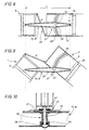
- the connecting rod oblique 20 When operating in curves, the connecting rod oblique 20 pushes or pulls the opposite corner of the trailer constituting for it a bond which imposes on it when cornering a trajectory that fits better in the channel assigned to it, as shown in Figure 3. This characteristic results from the diagonal arrangement of the oblique rod 20.
- center of pivot 18 can be anywhere trailer chassis 8 from the axles to the front of the trailer.
- the swiveling drawbar 13 is a telescopic swiveling drawbar mechanical 37, entirely free and passive, i.e. that he has no active means extension / withdrawal or recall, but also that slides freely without constraint for example without braking or damping force to present different lengths for example L2 between a value minimum L1 and maximum length L3 ( Figures 16 to 18). Furthermore, it is carried out with means simple mechanical. For example, it is a beam hollow in which is slidably fitted another beam forming the bar of the pivoting drawbar 37.
- drawbar 37 pivoting around the pivot center 18 has safety stops designed to limit its acceleration or braking.
- the telescopic pivoting drawbar 37 is completed by a double articulated link 38 with two rigid connecting rods 39 and 40 constituted by the symmetrical addition to the first connecting rod 39 of a second oblique rigid connecting rod 40 articulated by one of its ends at the rear of the truck and by its other end at the front of the trailer.
- These two symmetrical connecting rods called connecting rods crossed 39 and 40 of equal constant length referenced D1 and D2 each extend obliquely and diagonally to the line direction right, from one of the corners 23,24 of the front front 41 of the trailer to one of the corresponding corners 21,22 of the front rear 42 of chassis 6 of the truck.
- the corners specific to the end of the same rod are diagonally opposites.
- These crossed connecting rods are articulated by their ends either directly or by through corner pieces attached to the forehead front 41 of trailer chassis and rear front 42 of the truck chassis.
- the pivot center 18 can also here be anywhere in chassis 8 of trailer from the axles to the front of the trailer.
- Cross rods prevent telescoping opposite corners of the trailer and truck.
- the pivot center 18 is, according to the variants, the front end ring 25 pivoting around a substantially vertical axis 43 ( Figures 1 to 7 and 11 15) or the pivot axis of the drawbar end 26 ( Figures 8 and 9).
- the front end 25 is cantilevered at the front under the trailer chassis 8. He is trained conventionally of a circular body, integral with the trailer chassis on which a part is mounted cylindrical secured to the end of the pivoting drawbar. The return of the cylindrical part presses on a circular crown of beads.
- Axis 43 of the front end circle is preferably slightly tilted forward of in order to improve the stability of the whole road by rolling.
- drawbar can also be coupled to a removable body carried by the truck and not directly on the truck.
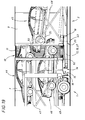
- the invention has the important advantage of allowing transport, cantilevered or projecting in the space between the two vehicles, indivisible charges, for example cars such that 44,45 and 46 carried by individual trays 47,48 and 49 fitted with extensions 50,51 and 52.
Landscapes
- Engineering & Computer Science (AREA)
- Transportation (AREA)
- Mechanical Engineering (AREA)
- Body Structure For Vehicles (AREA)
- Regulating Braking Force (AREA)
- Vehicle Body Suspensions (AREA)
- Control Of Driving Devices And Active Controlling Of Vehicle (AREA)
- Vehicle Cleaning, Maintenance, Repair, Refitting, And Outriggers (AREA)
- Agricultural Machines (AREA)
- Handcart (AREA)
Abstract
Description
La présente invention se rapporte à un
attelage mécanique entre un camion et une remorque, à
commande de la trajectoire de la remorque, conformément aux caractéristiques du préambule de la revendication 1.The present invention relates to a
mechanical coupling between a truck and a trailer,
control of the trajectory of the trailer, in accordance with the characteristics of the preamble of
L'attelage mécanique selon l'invention est formé d'un timon et d'au moins une liaison oblique, rigide, articulée par une de ses extrémités à la remorque et par son autre extrémité au camion.The mechanical coupling according to the invention is formed of a drawbar and at least one oblique connection, rigid, articulated by one of its ends to the trailer and by its other end to the truck.
De façon générale, il est souhaitable que les attelages routiers procurent à la remorque une trajectoire dégageante pour qu'elle se trouve dans une meilleure position dans les virages et en sortie de courbes en vue de mieux suivre la voie routière qui est assignée à l'ensemble camion-remorque.In general, it is desirable that the road hitches provide the trailer with clearing trajectory so that it is in a better position in turns and out of curves in order to better follow the road lane which is assigned to the truck-trailer combination.
Les moyens existants procurant le caractère dégageant pour la trajectoire de la remorque permettent non seulement d'éviter le télescopage de la remorque et du camion ou de leur chargement dans les virages, mais aussi de réaliser une véritable commande de trajectoire de la remorque qui a pour but de corriger sa position dans les virages et à la sortie des courbes.Existing means providing character clearing for the trajectory of the trailer allow not only to avoid telescoping of the trailer and from the truck or their load around corners, but also to carry out a real trajectory control of the trailer which aims to correct its position in turns and at the end of curves.
On connaít par DE-U-1 771 844, déposé le 29.06.1956 au nom de KASSBOHRER, un attelage entre un camion et une remorque à train avant directeur.We know by DE-U-1 771 844, filed on 29.06.1956 in the name of KASSBOHRER, a team between a truck and a steering front axle trailer.
Cet attelage est formé d'une barre d'attelage et d'une bielle oblique articulée sur une interface de train avant directeur.This hitch consists of a drawbar and an oblique link articulated on a train interface before director.
Selon la première variante, la barre d'attelage est montée articulée à son extrémité avant sur le crochet de remorquage du camion et à son extrémité arrière sur le rond d'avant train constituant classiquement l'interface entre l'essieu avant et l'attelage.According to the first variant, the drawbar is hinged mounted at its front end on the hook towing the truck and at its rear end on the round front end conventionally constituting the interface between the front axle and the hitch.
Selon une deuxième variante (figure 2), l'essieu avant est fixe. Un organe intermédiaire de commande assure l'orientation directionnelle des roues avant à partir de la direction de la force de traction exercée sur le timon.According to a second variant (FIG. 2), the axle front is fixed. An intermediate control unit ensures the directional orientation of the front wheels from the direction of the pulling force exerted on the drawbar.
Cette invention met en oeuvre une barre d'attelage, une bielle oblique, une interface de commande et le train avant d'une remorque dite à train avant directeur.This invention uses a drawbar, an oblique rod, a control interface and the train front of a trailer known as a steering front axle.
La bielle oblique permet de procurer une trajectoire dégageante en virage du coin de la remorque sur lequel elle est articulée en l'éloignant du coin arrière correspondant du camion.The oblique connecting rod provides a trajectory cornering cornerer of the trailer on which it is articulated away from the corresponding rear corner of the truck.
La barre d'attelage ne transmet pas de charge notable au véhicule tracteur car le poids de la partie avant est supporté par le train avant directeur.The drawbar does not transmit a significant load to the towing vehicle because the weight of the front part is supported by the steering front axle.
Cet attelage est spécifique à une remorque à train avant directeur.This coupling is specific to a train trailer before director.
La présente invention a pour but de procurer une remorque à essieux centraux qui présente ces caractéristiques et assure une trajectoire dégageante au coin de la remorque.The object of the present invention is to provide a center axle trailer with these characteristics and ensures a clear path at the corner of the trailer.
La présente invention a pour but d'arriver à ce résultat avec des moyens simples uniquement mécaniques à savoir un timon de longueur constante ou un timon télescopique passif et libre en extension-retrait, c'est-à-dire non rappelé sous l'effet d'un fluide ou analogue et une ou deux bielle(s) oblique(s) rigide(s), de longueur constante, articulée(s) sur la remorque et sur le camion.The object of the present invention is to arrive at this result with simple means only mechanical i.e. a drawbar of constant length or a passive and free telescopic drawbar in extension-retraction, that is to say not recalled under the effect of a fluid or the like and one or two oblique rod (s) rigid (s), of constant length, articulated on the trailer and on the truck.
L'invention a aussi pour but avec un attelage mécanique simple de conférer à la remorque une trajectoire dégageante qui permette le transport de charges dépassant de l'avant de la remorque et/ou de l'arrière du camion.The invention also aims with a hitch simple mechanics to give the trailer a clearing path which allows the transport of loads protruding from the front of the trailer and / or the back of the truck.
Elle a également pour but de réaliser un attelage purement mécanique et le plus simple possible en vue d'en augmenter la fiabilité et d'en diminuer le coût.It also aims to achieve a purely mechanical coupling and as simple as possible in order to increase reliability and decrease cost.
Elle a finalement pour but de permettre l'utilisation d'un soufflet de protection entre le camion et la remorque dont la déformation s'effectue selon une courbure générale en arc de cercle dégageant.It ultimately aims to allow the use of a protective bellows between the truck and trailer whose deformation takes place according to a general curvature in a free arc.
L'invention se propose d'atteindre ces
résultats plus spécifiquement avec un attelage conforme aux caractéristiques de la revendication 1.The invention proposes to achieve these
results more specifically with a coupling conforming to the characteristics of
A cet effet, on prévoit entre le camion et la remorque un attelage mécanique formé d'une part d'un timon dont l'extrémité avant est accrochée à l'arrière, par exemple en porte-à-faux du camion, et dont l'extrémité arrière fait partie d'un centre de pivotement autour d'un axe sensiblement vertical monté sur le châssis de la remorque et d'autre part d'au moins une bielle oblique par rapport à la direction de ligne droite, bielle rigide et de longueur constante, montée articulée par une de ses extrémités sur l'arrière du camion et par son autre extrémité à l'arrière de la remorque.For this purpose, provision is made between the truck and the tows a mechanical coupling formed on the one hand by a drawbar whose front end is hooked at the rear, for example overhanging the truck, and whose the rear end is part of a center of pivoting around a substantially vertical axis mounted on the trailer chassis and on the other hand at minus a connecting rod oblique to the direction of straight line, rigid rod and constant length, articulated climb by one of its ends on the back of the truck and by its other end to the rear of the trailer.
Conformément à une variante perfectionnée, la liaison formée d'une seule bielle oblique est doublée par une seconde bielle oblique pour se transformer en une liaison à bielles croisées disposées, en configuration de ligne droite, selon des diagonales dans l'espace existant entre le camion et la remorque.In accordance with an improved variant, the link formed by a single oblique link is doubled by a second oblique rod to transform into a link with crossed connecting rods arranged in straight line configuration, along diagonals in the space between the truck and the trailer.
Cette invention, dans son application d'attelage court apporte plusieurs avantages supplémentaires importants dont la possibilité avec un espace camion-remorque réduit de placer des charges indivisibles en porte-à-faux et imbriquées saillantes de l'arrière du camion et/ou de l'avant de la remorque.This invention, in its application short hitch brings several advantages additional important including the possibility with a reduced truck-trailer space to place loads indivisible cantilevered and projecting nested from the back of the truck and / or the front of the trailer.
Un autre intérêt concerne le moindre coût lié à la simplicité des moyens mis en oeuvre et à leur aspect passif.Another interest concerns the lower cost the simplicity of the means used and their passive aspect.
D'autres caractéristiques et avantages de l'invention apparaítront dans la description qui suit, donnée à titre d'exemple et accompagnée des dessins qui représentent :
- la figure 1 : une vue générale de profil d'une première réalisation de l'ensemble camion-remorque avec un soufflet de protection ;
- la figure 2 : une vue générale de profil de l'ensemble camion-remorque avec soufflet de protection selon une réalisation entièrement couverte ;
- la figure 3 : une vue schématique en plan d'une forme de réalisation à timon rigide de longueur constante dans une position de ligne droite et une position de virage ;
- la figure 4 : une vue géométrique composite illustrant deux positions des moyens constituant l'attelage représenté sur la figure précédente ;
- les figures de 5 à 7 : des schémas successifs montrant la longueur L constante du timon pour la réalisation représentée ci-dessus ;
- les figures de 8 et 9 : des schémas successifs montrant la longueur L constante du timon selon une position de ligne droite et une position de virage pour la variante du premier mode de réalisation ;
- la figure 10 : une vue en coupe longitudinale perpendiculaire au châssis de remorque, le long du timon et à travers la piste montrant la liaison entre le timon et la piste ;
- la figure 11 : une vue schématique en plan d'une variante à timon extensible à deux bielles croisées selon une position de ligne droite et une position de virage ;
- la figure 12 : une vue géométrique illustrant deux positions dont une de ligne droite des moyens constituant l'attelage de la réalisation représentée sur la figure 11 ;
- les figures 13 à 15 : des schémas successifs montrant l'allongement du timon dans le cas de la réalisation à timon extensible ;
- les figures 16 à 18 : des schémas successifs montrant la variation de l'espace camion-remorque dans le cas de la réalisation à timon extensible ;
- la figure 19 : une vue de profil au niveau de l'espace entre camion et remorque montrant une imbrication entre des voitures constituant un exemple de chargement ;
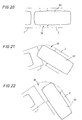
- les figures 20 à 22 : des schémas successifs illustrant les positions en ligne droite puis en virage d'une voiture chevauchant l'espace camion-remorque.
- Figure 1: a general profile view of a first embodiment of the truck-trailer assembly with a protective bellows;
- Figure 2: a general profile view of the truck-trailer assembly with protective bellows according to an entirely covered embodiment;
- Figure 3: a schematic plan view of an embodiment with a rigid drawbar of constant length in a straight line position and a turning position;
- Figure 4: a composite geometric view illustrating two positions of the means constituting the coupling shown in the previous figure;
- Figures 5 to 7: successive diagrams showing the constant length L of the drawbar for the embodiment shown above;
- Figures 8 and 9: successive diagrams showing the constant length L of the drawbar in a straight line position and a turning position for the variant of the first embodiment;
- FIG. 10: a view in longitudinal section perpendicular to the trailer chassis, along the drawbar and across the track showing the connection between the drawbar and the track;
- FIG. 11: a schematic plan view of a variant with an extendable drawbar with two cross rods crossed in a straight line position and a turning position;
- FIG. 12: a geometrical view illustrating two positions, one of which is a straight line, of the means constituting the coupling of the embodiment shown in FIG. 11;
- FIGS. 13 to 15: successive diagrams showing the elongation of the drawbar in the case of the embodiment with extendable drawbar;
- Figures 16 to 18: successive diagrams showing the variation of the truck-trailer space in the case of the construction with extendable drawbar;
- Figure 19: a side view at the space between truck and trailer showing a nesting between cars constituting an example of loading;
- Figures 20 to 22: successive diagrams illustrating the positions in a straight line then in a bend of a car straddling the truck-trailer space.
La présente invention se rapporte à un
attelage mécanique entre un véhicule à moteur, appelé
ici pour des raisons de simplification camion 1, et une
remorque 2.The present invention relates to a
mechanical coupling between a motor vehicle, called
here for the sake of
La remorque 2 est représentée comme une
remorque à essieux centraux 3 et 4 et sera décrite
comme telle.
Si d'autres types de remorques conviennent, il est bien entendu qu'ils sont visés par l'invention.If other types of trailers are suitable, it is understood that they are targeted by the invention.
Le camion 1 présente une cabine 5 et un
châssis 6, ce dernier étant surmonté d'une carrosserie
7 fixe ou déposable. Cette carrosserie est prévue par
exemple, mais non nécessairement, pour transporter des
voitures sur des plates-formes ou des plateaux
individuels de chargement.
Il en est de même pour la remorque qui
comprend un châssis 8 sur lequel est monté par exemple
une carrosserie 9 porte-voitures avec plates-formes ou
plateaux individuels de chargement.It is the same for the trailer which
includes a
Les véhicules, camion et remorque, délimitent
entre eux un espace intermédiaire de liaison 10 camion-remorque,
par exemple protégé par un soufflet 11, comme
représenté sur les figures 1 et 2.The vehicles, truck and trailer, delimit
between them an intermediate space for connecting 10 truck-trailer,
for example protected by a
La présente invention porte sur la liaison entre camion et remorque formant un attelage mécanique 12 à commande de la trajectoire de la remorque formé d'un timon pivotant et d'au moins une liaison oblique par rapport à la direction de ligne droite.The present invention relates to binding between truck and trailer forming a mechanical coupling 12 to control the trajectory of the trailer formed a pivoting drawbar and at least one oblique connection relative to the straight line direction.
Les figures 1 et 2 représentent l'ensemble camion-remorque avec un timon pivotant quelconque 13. Comme on le verra ci-après, ce timon pivotant peut être rigide et de longueur constante dans un premier mode de réalisation à une seule liaison oblique ou bien télescopique libre et passif dans une deuxième forme de réalisation à liaison oblique double.Figures 1 and 2 show the whole trailer truck with any swivel drawbar 13. As will be seen below, this pivoting drawbar can be rigid and of constant length in a first mode of realization with a single oblique connection or free and passive telescopic in a second form of double oblique connection.
Le timon pivotant 13 présente d'une part une
extrémité avant 14 reliée à un point d'accouplement 15
à crochet porté par un ensemble mécanique transversal
16 solidaire du châssis 6 de camion ou de la
carrosserie présentant par exemple une extension
arrière en porte-à-faux et d'autre part une extrémité
arrière 17 faisant partie ou constituant une des pièces
d'un centre de pivotement 18 monté en porte-à-faux à
l'avant du châssis 8 de remorque ou au voisinage de
celle-ci.The pivoting drawbar 13 has on the one hand a
Selon les deux variantes du premier mode de
réalisation représentée sur les figures 3 à 10, le
timon pivotant 13 est un timon pivotant rigide 19
pivotant autour du centre de pivotement 18. Ce timon
est de longueur L constante et la liaison oblique est
constituée par une bielle rigide 20 de longueur D
constante. Elle traverse en oblique le plan
longitudinal médian de ligne droite du véhicule selon
une disposition en diagonale et se trouve articulée par
ses extrémités au niveau, par exemple d'un coin arrière
21 ou 22 du camion et d'un coin avant 23 ou 24 de la
remorque.According to the two variants of the first mode of
embodiment shown in Figures 3 to 10, the
swivel drawbar 13 is a rigid swivel drawbar 19
pivoting around the
Selon la première variante le centre de
pivotement 18 est réalisé sous la forme d'un rond
d'avant train 25 monté en porte-à-faux à l'avant du
châssis 8 de remorque. According to the first variant, the center of
Une deuxième variante de la première forme de
réalisation, met en oeuvre un centre de pivotement 18
équivalent au rond d'avant train de la première
variante qui procure donc les mêmes effets.A second variant of the first form of
realization, implements a
Selon cette deuxième variante, le rond
d'avant train 25 est remplacé par un axe pivotant
d'extrémité 26 monté vertical en sous-face du châssis 8
de remorque en position médiane et perpendiculaire à ce
châssis. L'ensemble est complété par un moyen de
liaison-soutien 27 de la remorque à l'avant. Ce moyen
de liaison-soutien 27 consiste dans l'exemple
représenté en une piste 28 en arc de cercle et en un
appui-glissant sur cette piste sur une zone de portée
29 formée par la surface du timon en regard de la piste
28 en arc de cercle complétée par une liaison glissante
d'assemblage 30 entre le timon et la structure de la
piste 28 en arc de cercle. Cette liaison permet de
maintenir la partie avant du châssis 8 de remorque
contre le timon et d'empêcher ainsi un débattement
entre le timon et la remorque dans le cas d'une charge
plus importante à l'arrière de la remorque.According to this second variant, the round
Cette liaison permet une sécurité
supplémentaire en cas de rupture de l'axe 26 de
pivotement.This link allows security
additional in the event of the
Plus particulièrement, et comme on peut le
constater sur la vue en coupe de la figure 10, la piste
en arc de cercle présente en sous face des zones de
contact lubrifiées ou revêtues d'une couche ou d'une
pièce intercalaire 31 d'une matière ou d'un matériau
anti-friction. La liaison 30 est réalisée sous la forme
d'un boulon de liaison 32 dont la tête appuie à travers
une rondelle plate 33 et un intercalaire anti-friction
34 contre les faces internes des bords de la piste en
arc de cercle.More particularly, and as can be seen
see in the sectional view of Figure 10, the track
in an arc of a circle present on the underside of the zones of
contact lubricated or coated with a layer or
insert 31 of a material or material
anti-friction. The
Pour améliorer la stabilité en roulage, le
boulon de liaison 32 présente une précontrainte, par
exemple sous la forme d'une rondelle 35 à effet
élastique prévue à son extrémité inférieure au
voisinage de son écrou de serrage 36.To improve rolling stability, the
connecting
Bien entendu, l'ensemble piste et liaison d'assemblage peut être remplacé par un moyen équivalent d'appui-glissement.Of course, the track and link assembly assembly can be replaced by equivalent means support-slip.
Les articulations d'extrémités de la bielle
oblique rigide 20 sont du type à rotules ou des
articulations de pivotement à degré(s)
supplémentaire(s) permettant le débattement approprié
pour absorber les mouvements de roulis et de tangage.The end joints of the connecting rod
A l'observation des figures 5 à 10 on
remarque que la relation entre la direction du camion
et celle de la remorque comprend comme contraintes la
longueur L constante du timon pivotant et la longueur D
constante de la bielle oblique de liaison 20. Seul le
timon reprend les efforts dus au report de charge
vertical de la remorque.By observing Figures 5 to 10 we
note that the relationship between the direction of the truck
and that of the trailer includes as constraints the
constant length L of the swiveling drawbar and length D
constant of the
En fonctionnement dans les courbes, la bielle
oblique 20 pousse ou tire le coin opposé de la remorque
constituant pour celle-ci une liaison qui lui impose
dans les virages une trajectoire s'inscrivant mieux
dans la voie qui lui est assignée, comme représenté sur
la figure 3. Cette caractéristique résulte de la
disposition en diagonale de la bielle oblique 20.When operating in curves, the connecting
De façon plus générale, le centre de
pivotement 18 peut se trouver en un endroit quelconque
du châssis 8 de remorque à partir des essieux jusqu'à
l'avant de la remorque.More generally, the center of
Selon la deuxième forme de réalisation, le
timon pivotant 13 est un timon pivotant télescopique
mécanique 37, entièrement libre et passif, c'est-à-dire
qu'il ne présente aucun moyen actif
d'allongement/retrait ou de rappel, mais aussi qu'il
coulisse librement sans contrainte par exemple sans
force de freinage ou d'amortissement pour présenter des
longueurs différentes par exemple L2 entre une valeur
minimale L1 et une longueur maximale L3 (figures 16 à
18). Par ailleurs, il est réalisé avec des moyens
mécaniques simples. Il s'agit par exemple, d'une poutre
creuse dans laquelle vient s'emmancher à coulissement
une autre poutre formant la barre du timon pivotant 37.According to the second embodiment, the
swiveling drawbar 13 is a telescopic swiveling drawbar
mechanical 37, entirely free and passive, i.e.
that he has no active means
extension / withdrawal or recall, but also that
slides freely without constraint for example without
braking or damping force to present
different lengths for example L2 between a value
minimum L1 and maximum length L3 (Figures 16 to
18). Furthermore, it is carried out with means
simple mechanical. For example, it is a beam
hollow in which is slidably fitted
another beam forming the bar of the pivoting
Bien entendu, le timon pivotant 37 autour du
centre de pivotement 18 présente des butées de sécurité
destinées à limiter sa course en accélération ou en
freinage.Of course, the
Seul le timon reprend les efforts dus au report de charge vertical de la remorque.Only the drawbar takes up the efforts due to vertical load transfer of the trailer.
Selon cette deuxième forme de réalisation, le
timon pivotant télescopique 37 est complété par une
liaison articulée double 38 à deux bielles rigides 39
et 40 constituée par l'addition symétrique à la
première bielle 39 d'une deuxième bielle rigide oblique
40 articulée par l'une de ses extrémités à l'arrière du
camion et par son autre extrémité à l'avant de la
remorque. Ces deux bielles symétriques appelées bielles
croisées 39 et 40 de longueur constante égale
référencées D1 et D2 s'étendent chacune en oblique et
en diagonale par rapport à la direction de ligne
droite, d'un des coins 23,24 du front avant 41 de la
remorque à un des coins correspondants 21,22 du front
arrière 42 du châssis 6 du camion. Les coins propres à
l'extrémité d'une même bielle sont diagonalement
opposés.According to this second embodiment, the
Ces bielles croisées sont articulées par
leurs extrémités soit directement soit par
l'intermédiaire de pièces de coin solidaires du front
avant 41 du châssis de remorque et du front arrière 42
du châssis de camion.These crossed connecting rods are articulated by
their ends either directly or by
through corner pieces attached to the
Elles sont montées chacune au niveau des extrémités par des articulations du type à rotule qui permettent d'absorber les mouvements de roulis et de tangage.They are each mounted at the level of ends by ball-and-socket type joints absorb the roll and pitch.
Le centre de pivotement 18 peut également ici
se trouver en un endroit quelconque du châssis 8 de
remorque à partir des essieux jusqu'à l'avant de la
remorque.The
Pour le premier but visé, il est souhaitable que ces bielles soient les plus longues possibles. La trajectoire de la remorque déborde alors le moins possible par rapport à la trace du camion.For the first goal, it is desirable that these rods are as long as possible. The trailer trajectory then overflows the least possible compared to the track of the truck.
Sans pour autant se limiter, on peut ainsi déterminer les emplacements optimums des points d'articulation sur les fronts avant 41 et arrière 42 respectivement de remorque et de camion.Without being limited, we can thus determine optimum locations of points articulation on the front 41 and rear 42 fronts trailer and truck respectively.
Il s'agit par exemple des emplacements 21 à
24 au niveau de la base des arêtes, c'est-à-dire à
l'extrémité avant du châssis de remorque et à
l'extrémité arrière du châssis du camion ou bien
légèrement en retrait sous l'un et l'autre des deux
châssis comme représenté sur les figures 4 à 7.These are for
A l'observation des figures 13 à 18, on remarque que la relation entre l'orientation du camion et celle de la remorque ne comprend plus comme constantes que les longueurs D1 et D2 des bielles croisées.By observing Figures 13 to 18, we notice that the relationship between the orientation of the truck and that of the trailer no longer understands as constants that the lengths D1 and D2 of the connecting rods crossed.
Comme il apparait sur les schémas, le fonctionnement symétrique et simultané des deux bielles est analogue à celui du premier mode de réalisation.As it appears on the diagrams, the symmetrical and simultaneous operation of the two connecting rods is analogous to that of the first embodiment.
Les bielles croisées évitent le télescopage des coins en regard de la remorque et du camion.Cross rods prevent telescoping opposite corners of the trailer and truck.
Le centre de pivotement 18 est, selon les
variantes, le rond d'avant train 25 pivotant autour
d'un axe 43 sensiblement vertical (figures 1 à 7 et 11
à 15) ou l'axe de pivotement d'extrémité 26 du timon
(figures 8 et 9).The
En ce qui concerne la première variante, le
rond d'avant train 25 est monté en porte-à-faux à
l'avant sous le châssis 8 de remorque. Il est formé
classiquement d'un corps circulaire, solidaire du
châssis de remorque sur lequel est montée une pièce
cylindrique solidaire de l'extrémité du timon pivotant.
Le retour de la pièce cylindrique appuie sur une
couronne circulaire de billes.As regards the first variant, the
L'axe 43 du rond d'avant train est
préférentiellement légèrement incliné vers l'avant de
façon à améliorer la stabilité de l'ensemble routier en
roulage.
Il y a lieu de remarquer ici que le timon peut également être attelé à une carrosserie déposable portée par le camion et non pas directement sur le camion.It should be noted here that the drawbar can also be coupled to a removable body carried by the truck and not directly on the truck.
Comme illustré par les figures 16 à 19,
l'invention présente l'important avantage de permettre
le transport, en porte-à-faux ou en saillie dans
l'espace intermédiaire entre les deux véhicules, de
charges indivisibles, par exemple des voitures telles
que 44,45 et 46 portées par des plateaux individuels
47,48 et 49 équipés de rallonges 50,51 et 52. Ceci
confère à l'invention un intérêt tout particulier dans
le cadre du transport de voitures notamment dans le cas
d'un transport bâché ou plus généralement fermé et
comportant un soufflet entre camion et remorque.As shown in Figures 16-19,
the invention has the important advantage of allowing
transport, cantilevered or projecting in
the space between the two vehicles,
indivisible charges, for example cars such
that 44,45 and 46 carried by
Cette possibilité de chevauchement de
l'espace intermédiaire de liaison 10 est plus
particulièrement illustrée par les figures 17 à 19
montrant en virage, dans le cas d'une voiture 53
chevauchante, de quelle façon l'espace intermédiaire de
liaison 10 peut être exploité par l'invention. Le
caractère dégageant de la liaison permet d'augmenter
sensiblement le porte-à-faux de la voiture au-dessus de
la limite arrière du camion sans risquer de télescoper
dans les virages les structures voisines de sa
carrosserie.This possibility of overlapping
the
Claims (14)
- Coupling gear comprising a truck (1) and a trailer (2) as well as a linkage between the truck (1) and the trailer (2) which allows the control of the path of the trailer with a view to obtaining a clearance path, which linkage is formed, on the one hand, by a drawbar (13) whose front end (14) is fastened, free to pivot, to the rear of the truck (1) and whose rear end (17) forms part of a centre (18) for pivoting about a substantially vertical axis, the pivoting centre (18) being mounted on the chassis of the trailer (2), and, on the other hand, by at least one diagonally positioned oblique connecting rod (20, 39, 40) which is of constant length and of which one end is articulated to the front of the trailer (2) and the opposing end to the rear of the truck (1), the coupling gear being characterised in that the trailer (2) comprises, at a substantially central position or at the rear, a train of at least one axle (3, 4) which leaves free that portion of the chassis (8) of the trailer (2) which extends from the front end thereof as far as the front axle (3) of the train of at least one axle (3, 4), and in that the pivoting centre (18) is mounted on the free portion of the chassis (8) of the trailer (2) in a position which is out of true and which is located between the front of the trailer (2) and the front axle (3) of the train of at least one axle (3, 4), in that at least the oblique connecting rod (20, 39, 40) connects in an articulated manner and at a diagonal position the front of the trailer (2) to the rear of the truck (1), and in that the drawbar (13) is fixed in terms of vertical movements relative to the chassis (8) of the trailer (2), the assembly constituted by the drawbar (13) and the pivoting centre (18) forming a permanent support or retention linkage for any vertical force or load acting on the trailer (2).
- Mechanical coupling gear according to claim 1, characterised in that the coupling gear comprises a single oblique connecting rod (20) and a drawbar (13) of fixed length.
- Mechanical coupling gear according to either of the preceding claims, characterised in that the pivoting centre (18) is a circular member of the front train (25) of the trailer and pivots about an axis (43).
- Mechanical coupling gear according to the preceding claim, characterised in that the pivoting axis (43) is slightly inclined forwards.
- Mechanical coupling gear according to any one of claims 1, 2 or 3, characterised in that the pivoting centre (18) is a pivoting axis (26) at the rear end (17) of the pivoting drawbar (13).
- Mechanical coupling gear according to the preceding claim, characterised in that the pivoting centre (26) is completed by a support means (27) of the front of the trailer (2).
- Mechanical coupling gear according to the preceding claim, characterised in that the support means is a linkage-support means (27).
- Mechanical coupling gear according to claim 6 or claim 7, characterised in that the support means or linkage-support means (27) comprises a track (28), which is in the shape of a circular arc and which is integral with the trailer, and a slide-support of the track on a supporting region (29) which is formed by the surface of the drawbar (13) opposite the track (28) in the shape of a circular arc which is completed by a sliding assembly linkage (30) between the drawbar (13) and the structure of the track (28) in the shape of a circular arc, and in that the sliding assembly linkage (30) between the drawbar (13) and the structure of the track (28) in the shape of a circular arc is produced in the form of a connecting pin (32), whose head presses, by means of a washer (33) and an anti-friction insert (34), against the inner faces of the edges of the track (28) in the shape of a circular arc, the connecting pin (32) having a mechanical bias in the form of a washer (35) which acts resiliently and which is provided at the lower end adjacent to the tightening nut (36) thereof.
- Mechanical coupling gear according to any one of the preceding claims, characterised in that the single oblique connecting rod is complemented by an oblique connecting rod which is identical and symmetrical in order to form a linkage (30) with two oblique crossed connecting rods (39, 40), which are arranged diagonally relative to the straight line axis and which are identically articulated, and in that the pivoting drawbar which is fixed in terms of vertical movements is a telescopic drawbar (37).
- Mechanical coupling gear according to the preceding claim, characterised in that the telescopic pivoting drawbar (37) is passive and free to move in an extending or retracting manner.
- Mechanical coupling gear according to any one of the preceding claims, characterised in that the ends of the oblique connecting rod(s) are each articulated to a front corner (23, 24) of the trailer and a rear corner (21, 22) of the truck.
- Mechanical coupling gear according to any one of the preceding claims, characterised in that the end articulations of the connecting rod(s) are articulations of the spherical plain bearing type.
- Mechanical coupling gear according to any one of the preceding claims, characterised in that the intermediate connecting space (10) located between the truck (1) and the trailer (2) is protected by a bellows (11).
- Mechanical coupling gear according to any one of the preceding claims, characterised in that the intermediate connecting space (10) located between the truck (1) and the trailer (2) is of short length.
Applications Claiming Priority (2)
| Application Number | Priority Date | Filing Date | Title |
|---|---|---|---|
| FR9511586 | 1995-09-28 | ||
| FR9511586A FR2739326B1 (en) | 1995-09-28 | 1995-09-28 | MECHANICAL HITCH BETWEEN A TRUCK AND A TRAILER WITH CONTROL OF THE TRAILER TRAILER |
Publications (2)
| Publication Number | Publication Date |
|---|---|
| EP0765770A1 EP0765770A1 (en) | 1997-04-02 |
| EP0765770B1 true EP0765770B1 (en) | 2000-11-22 |
Family
ID=9483164
Family Applications (1)
| Application Number | Title | Priority Date | Filing Date |
|---|---|---|---|
| EP96440075A Expired - Lifetime EP0765770B1 (en) | 1995-09-28 | 1996-09-27 | Coupling device between a truck and a trailer with control of path movement of trailer |
Country Status (6)
| Country | Link |
|---|---|
| US (1) | US6241270B1 (en) |
| EP (1) | EP0765770B1 (en) |
| AT (1) | ATE197693T1 (en) |
| DE (1) | DE69611022T2 (en) |
| ES (1) | ES2152504T3 (en) |
| FR (1) | FR2739326B1 (en) |
Families Citing this family (5)
| Publication number | Priority date | Publication date | Assignee | Title |
|---|---|---|---|---|
| US8459625B1 (en) * | 2009-03-31 | 2013-06-11 | Honda Motor Co., Ltd. | Device for securing vehicle body to conveyor carrier |
| US8621991B1 (en) | 2010-08-23 | 2014-01-07 | Rodolfo Lopez | Pistol grip spring compressor system and method for maintaining compression on a valve spring |
| RU2503552C1 (en) * | 2012-06-05 | 2014-01-10 | Федеральное государственное бюджетное образовательное учреждение высшего профессионального образования "Алтайский государственный технический университет им. И.И. Ползунова" (АлтГТУ) | Tractor coupler |
| CN103786800B (en) * | 2014-01-20 | 2015-03-11 | 吉林大学 | Half hanging type highway passenger vehicle |
| IT201900012120A1 (en) | 2019-07-17 | 2021-01-17 | Univ Degli Studi Di Firenze | MECHANICAL COUPLING DEVICE BETWEEN VEHICLES, IN PARTICULAR FOR CONVEYING AUTOMATIC VEHICLES |
Family Cites Families (20)
| Publication number | Priority date | Publication date | Assignee | Title |
|---|---|---|---|---|
| US1336665A (en) * | 1915-09-15 | 1920-04-13 | Eagle Wagon Works | Wagon-train |
| US1429734A (en) * | 1920-10-16 | 1922-09-19 | Charles S Hoffman | Trailer |
| US1758951A (en) * | 1927-11-11 | 1930-05-20 | Elmo W Johnson | Tractor hitch |
| US2133202A (en) * | 1937-04-07 | 1938-10-11 | Elmer G Lantz | Trailer hitch |
| US2256557A (en) * | 1940-08-30 | 1941-09-23 | Jr Alex H Gustin | Steering coupling mechanism |
| US2568261A (en) * | 1949-12-06 | 1951-09-18 | Albert H Stade | Stabilizer for house trailers |
| US2653032A (en) * | 1949-12-27 | 1953-09-22 | Walter E Ellis | Trailer steering hitch |
| US2685454A (en) * | 1953-01-30 | 1954-08-03 | Leslie L Patchett | Trailer stabilizing hitch |
| US2843417A (en) * | 1955-06-20 | 1958-07-15 | Karl Kassbohrer G M B H | Connecting means for the vehicles of link-trains |
| US2898126A (en) * | 1956-01-30 | 1959-08-04 | Roy A Loukonen | Draft hitches |
| DE1771844U (en) * | 1956-06-29 | 1958-08-07 | Kaessbohrer Fahrzeug Karl | COUPLING DEVICE FOR LOADS. |
| US3254905A (en) * | 1963-09-26 | 1966-06-07 | Standard Engineering Company | Anti-sway short-turn type hitch |
| GB1241542A (en) | 1967-07-20 | 1971-08-04 | Bakelite Xylonite Ltd | Fire retardants |
| US3955831A (en) * | 1974-03-07 | 1976-05-11 | Whitchurch Woodrow C | Compound trailer hitch with gooseneck support |
| DE3145871A1 (en) * | 1981-11-19 | 1983-06-01 | Egon Dipl.-Ing. La Force (F.H.), 8222 Ruhpolding | Trailer coupling device of a lorry |
| FR2517604A1 (en) * | 1981-12-09 | 1983-06-10 | Verdier Jean Jacques | Vehicle towing linkage for e.g. caravan or tailer - comprises two diagonal bars extending between opposite sides of towing vehicle and trailer |
| DE3150024A1 (en) * | 1981-12-17 | 1983-06-23 | Heinz-Jürgen 4600 Dortmund Winterhoff | Device for damping, in particular rolling motion in trailers, in particular caravans |
| US4598926A (en) * | 1982-09-30 | 1986-07-08 | Gallatin Norman W | Asymmetrical four-bar link trailer hitch |
| DE4136334C1 (en) * | 1991-11-05 | 1993-04-29 | Fahrzeugwerk Orthaus Gmbh & Co Kg, 4422 Ahaus, De | Short coupling on heavy goods vehicle - is used on central axle trailer and has hydraulic extension on corners to give adequate clearances. |
| FR2715624B1 (en) * | 1994-01-28 | 1996-03-15 | Lohr Ind | Directional control link for a rear steering road train. |
-
1995
- 1995-09-28 FR FR9511586A patent/FR2739326B1/en not_active Expired - Fee Related
-
1996
- 1996-09-27 DE DE69611022T patent/DE69611022T2/en not_active Expired - Lifetime
- 1996-09-27 US US08/721,091 patent/US6241270B1/en not_active Expired - Fee Related
- 1996-09-27 ES ES96440075T patent/ES2152504T3/en not_active Expired - Lifetime
- 1996-09-27 EP EP96440075A patent/EP0765770B1/en not_active Expired - Lifetime
- 1996-09-27 AT AT96440075T patent/ATE197693T1/en not_active IP Right Cessation
Also Published As
| Publication number | Publication date |
|---|---|
| DE69611022D1 (en) | 2000-12-28 |
| FR2739326A1 (en) | 1997-04-04 |
| US6241270B1 (en) | 2001-06-05 |
| ES2152504T3 (en) | 2001-02-01 |
| DE69611022T2 (en) | 2001-06-21 |
| ATE197693T1 (en) | 2000-12-15 |
| EP0765770A1 (en) | 1997-04-02 |
| FR2739326B1 (en) | 1997-12-05 |
Similar Documents
| Publication | Publication Date | Title |
|---|---|---|
| EP0960045B1 (en) | System for guiding a road vehicle axle along at least one rail on the ground | |
| CA2681344C (en) | Primary suspension device for a railway vehicle bogie | |
| FR3071813B1 (en) | ATTELABLE ROAD MOTOR VEHICLE HAS SUSPENSION AND COMPACT DIRECTION | |
| FR2630683A1 (en) | VEHICLE FOR MOVING VEHICLES ON RAILS | |
| EP0765770B1 (en) | Coupling device between a truck and a trailer with control of path movement of trailer | |
| FR2694240A1 (en) | Adjustable suspension for motor vehicle - has dead rear axle, and parallel link rear suspension, with ride height control and adjustable lower links | |
| EP0799730B1 (en) | Towing system for at least a towing vehicle and towed vehicle and motor vehicle capable of being used in such a system | |
| FR2822123A1 (en) | VEHICLE AXLE | |
| FR2903953A1 (en) | SELF-DIRECTING AXLE TOW ROLLER TRAIN FOR SEMI-TRAILER. | |
| FR2653712A1 (en) | TRAILER ROAD TRAILER CONVERTIBLE IN WAGON. | |
| EP0297009B1 (en) | Short coupling device with variable geometry, with jointed abutment supports movable in a circular arc, for balanced trailers and semi-trailers | |
| FR2870200A1 (en) | Swan neck for semi-trailers has arm with coupling plate provided with coupling pin protruding downwards below plate and rotates on arm around cross pin under action of hydraulic control cylinder connected to plate and supported on arm | |
| FR2517604A1 (en) | Vehicle towing linkage for e.g. caravan or tailer - comprises two diagonal bars extending between opposite sides of towing vehicle and trailer | |
| FR3037311A1 (en) | DEVICE FOR HANGING A TRAILER TO A TRACTOR VEHICLE AND ASSEMBLY FORMED BY THE COUPLING OF A TRACTOR VEHICLE AND A TRAILER COMPRISING SUCH A DEVICE | |
| FR2582609A1 (en) | Articulated composite link between a road trailer and a tractor vehicle | |
| FR3037309A1 (en) | SEMI-ARTICULATED TRAILER FOR REACHING A TRACTOR VEHICLE AND ATTACHED ASSEMBLY COMPRISING SUCH A TRAILER | |
| BE1006673A5 (en) | Device for road transport vehicle or vehicle and operation of a device. | |
| EP0038082A1 (en) | Traction coupling for articulated road vehicles | |
| EP1502811B1 (en) | Device for mounting a dump bucket on a vehicle frame and lorry comprising said device | |
| FR2948065A1 (en) | Motor vehicle e.g. lorry, for transporting e.g. people, has bar located at back of rear wheels, and coupling system comprising two parts that are connected with each other, where one of parts is mounted on trailer | |
| FR2512411A1 (en) | Self-steering vehicle trailer - has pair of wheels mounted on tiltable links on horizontal axle | |
| FR2485450A1 (en) | HITCH BAR TRAILER COMMANDING REAR WHEEL BRAKING | |
| EP1120333A1 (en) | Retractable gooseneck for semitrailer | |
| FR2782949A1 (en) | BEARING DEVICE FOR AGRICULTURAL MACHINE | |
| FR2894553A1 (en) | Semi-trailer self-steering axle assembly has independently pivoting right and left supports with each wheel's pivot lying in central plane of wheel |
Legal Events
| Date | Code | Title | Description |
|---|---|---|---|
| PUAI | Public reference made under article 153(3) epc to a published international application that has entered the european phase |
Free format text: ORIGINAL CODE: 0009012 |
|
| AK | Designated contracting states |
Kind code of ref document: A1 Designated state(s): AT BE DE ES FR GB IT NL PT |
|
| 17P | Request for examination filed |
Effective date: 19970905 |
|
| 17Q | First examination report despatched |
Effective date: 19981119 |
|
| GRAG | Despatch of communication of intention to grant |
Free format text: ORIGINAL CODE: EPIDOS AGRA |
|
| 17Q | First examination report despatched |
Effective date: 19981119 |
|
| GRAG | Despatch of communication of intention to grant |
Free format text: ORIGINAL CODE: EPIDOS AGRA |
|
| GRAG | Despatch of communication of intention to grant |
Free format text: ORIGINAL CODE: EPIDOS AGRA |
|
| GRAH | Despatch of communication of intention to grant a patent |
Free format text: ORIGINAL CODE: EPIDOS IGRA |
|
| RAP1 | Party data changed (applicant data changed or rights of an application transferred) |
Owner name: LOHR INDUSTRIE |
|
| GRAH | Despatch of communication of intention to grant a patent |
Free format text: ORIGINAL CODE: EPIDOS IGRA |
|
| GRAA | (expected) grant |
Free format text: ORIGINAL CODE: 0009210 |
|
| RAP1 | Party data changed (applicant data changed or rights of an application transferred) |
Owner name: LOHR ACTIVITES |
|
| RAP1 | Party data changed (applicant data changed or rights of an application transferred) |
Owner name: LOHR INDUSTRIE |
|
| AK | Designated contracting states |
Kind code of ref document: B1 Designated state(s): AT BE DE ES FR GB IT NL PT |
|
| PG25 | Lapsed in a contracting state [announced via postgrant information from national office to epo] |
Ref country code: NL Free format text: LAPSE BECAUSE OF FAILURE TO SUBMIT A TRANSLATION OF THE DESCRIPTION OR TO PAY THE FEE WITHIN THE PRESCRIBED TIME-LIMIT Effective date: 20001122 |
|
| REF | Corresponds to: |
Ref document number: 197693 Country of ref document: AT Date of ref document: 20001215 Kind code of ref document: T |
|
| REF | Corresponds to: |
Ref document number: 69611022 Country of ref document: DE Date of ref document: 20001228 |
|
| REG | Reference to a national code |
Ref country code: ES Ref legal event code: FG2A Ref document number: 2152504 Country of ref document: ES Kind code of ref document: T3 |
|
| ITF | It: translation for a ep patent filed | ||
| PG25 | Lapsed in a contracting state [announced via postgrant information from national office to epo] |
Ref country code: PT Free format text: LAPSE BECAUSE OF FAILURE TO SUBMIT A TRANSLATION OF THE DESCRIPTION OR TO PAY THE FEE WITHIN THE PRESCRIBED TIME-LIMIT Effective date: 20010222 |
|
| GBT | Gb: translation of ep patent filed (gb section 77(6)(a)/1977) |
Effective date: 20010226 |
|
| NLV1 | Nl: lapsed or annulled due to failure to fulfill the requirements of art. 29p and 29m of the patents act | ||
| PLBE | No opposition filed within time limit |
Free format text: ORIGINAL CODE: 0009261 |
|
| STAA | Information on the status of an ep patent application or granted ep patent |
Free format text: STATUS: NO OPPOSITION FILED WITHIN TIME LIMIT |
|
| PG25 | Lapsed in a contracting state [announced via postgrant information from national office to epo] |
Ref country code: BE Free format text: LAPSE BECAUSE OF NON-PAYMENT OF DUE FEES Effective date: 20010930 |
|
| 26N | No opposition filed | ||
| REG | Reference to a national code |
Ref country code: GB Ref legal event code: IF02 |
|
| BERE | Be: lapsed |
Owner name: LOHR INDUSTRIE Effective date: 20010930 |
|
| PGFP | Annual fee paid to national office [announced via postgrant information from national office to epo] |
Ref country code: AT Payment date: 20020925 Year of fee payment: 7 |
|
| PG25 | Lapsed in a contracting state [announced via postgrant information from national office to epo] |
Ref country code: AT Free format text: LAPSE BECAUSE OF NON-PAYMENT OF DUE FEES Effective date: 20030927 |
|
| REG | Reference to a national code |
Ref country code: FR Ref legal event code: GC Effective date: 20120924 |
|
| REG | Reference to a national code |
Ref country code: FR Ref legal event code: RG Effective date: 20121122 |
|
| REG | Reference to a national code |
Ref country code: FR Ref legal event code: PLFP Year of fee payment: 20 |
|
| PGFP | Annual fee paid to national office [announced via postgrant information from national office to epo] |
Ref country code: GB Payment date: 20150921 Year of fee payment: 20 Ref country code: ES Payment date: 20150928 Year of fee payment: 20 |
|
| PGFP | Annual fee paid to national office [announced via postgrant information from national office to epo] |
Ref country code: IT Payment date: 20150915 Year of fee payment: 20 |
|
| PGFP | Annual fee paid to national office [announced via postgrant information from national office to epo] |
Ref country code: DE Payment date: 20151021 Year of fee payment: 20 |
|
| PGFP | Annual fee paid to national office [announced via postgrant information from national office to epo] |
Ref country code: FR Payment date: 20150929 Year of fee payment: 20 |
|
| REG | Reference to a national code |
Ref country code: DE Ref legal event code: R071 Ref document number: 69611022 Country of ref document: DE |
|
| REG | Reference to a national code |
Ref country code: GB Ref legal event code: PE20 Expiry date: 20160926 |
|
| PG25 | Lapsed in a contracting state [announced via postgrant information from national office to epo] |
Ref country code: GB Free format text: LAPSE BECAUSE OF EXPIRATION OF PROTECTION Effective date: 20160926 |
|
| REG | Reference to a national code |
Ref country code: ES Ref legal event code: FD2A Effective date: 20170103 |
|
| PG25 | Lapsed in a contracting state [announced via postgrant information from national office to epo] |
Ref country code: ES Free format text: LAPSE BECAUSE OF EXPIRATION OF PROTECTION Effective date: 20160928 |