EP0765252B2 - Bench seat for motor vehicles, in particular camping cars - Google Patents
Bench seat for motor vehicles, in particular camping cars Download PDFInfo
- Publication number
- EP0765252B2 EP0765252B2 EP94918337A EP94918337A EP0765252B2 EP 0765252 B2 EP0765252 B2 EP 0765252B2 EP 94918337 A EP94918337 A EP 94918337A EP 94918337 A EP94918337 A EP 94918337A EP 0765252 B2 EP0765252 B2 EP 0765252B2
- Authority
- EP
- European Patent Office
- Prior art keywords
- column
- bench seat
- seat
- frame
- vehicle
- Prior art date
- Legal status (The legal status is an assumption and is not a legal conclusion. Google has not performed a legal analysis and makes no representation as to the accuracy of the status listed.)
- Expired - Lifetime
Links
Images


Classifications
-
- B—PERFORMING OPERATIONS; TRANSPORTING
- B60—VEHICLES IN GENERAL
- B60N—SEATS SPECIALLY ADAPTED FOR VEHICLES; VEHICLE PASSENGER ACCOMMODATION NOT OTHERWISE PROVIDED FOR
- B60N2/00—Seats specially adapted for vehicles; Arrangement or mounting of seats in vehicles
- B60N2/24—Seats specially adapted for vehicles; Arrangement or mounting of seats in vehicles for particular purposes or particular vehicles
- B60N2/242—Bus seats
-
- B—PERFORMING OPERATIONS; TRANSPORTING
- B60—VEHICLES IN GENERAL
- B60N—SEATS SPECIALLY ADAPTED FOR VEHICLES; VEHICLE PASSENGER ACCOMMODATION NOT OTHERWISE PROVIDED FOR
- B60N2/00—Seats specially adapted for vehicles; Arrangement or mounting of seats in vehicles
- B60N2/24—Seats specially adapted for vehicles; Arrangement or mounting of seats in vehicles for particular purposes or particular vehicles
- B60N2/42—Seats specially adapted for vehicles; Arrangement or mounting of seats in vehicles for particular purposes or particular vehicles the seat constructed to protect the occupant from the effect of abnormal g-forces, e.g. crash or safety seats
- B60N2/4207—Seats specially adapted for vehicles; Arrangement or mounting of seats in vehicles for particular purposes or particular vehicles the seat constructed to protect the occupant from the effect of abnormal g-forces, e.g. crash or safety seats characterised by the direction of the g-forces
- B60N2/4214—Seats specially adapted for vehicles; Arrangement or mounting of seats in vehicles for particular purposes or particular vehicles the seat constructed to protect the occupant from the effect of abnormal g-forces, e.g. crash or safety seats characterised by the direction of the g-forces longitudinal
- B60N2/4221—Seats specially adapted for vehicles; Arrangement or mounting of seats in vehicles for particular purposes or particular vehicles the seat constructed to protect the occupant from the effect of abnormal g-forces, e.g. crash or safety seats characterised by the direction of the g-forces longitudinal due to impact coming from the front
-
- B—PERFORMING OPERATIONS; TRANSPORTING
- B60—VEHICLES IN GENERAL
- B60N—SEATS SPECIALLY ADAPTED FOR VEHICLES; VEHICLE PASSENGER ACCOMMODATION NOT OTHERWISE PROVIDED FOR
- B60N2/00—Seats specially adapted for vehicles; Arrangement or mounting of seats in vehicles
- B60N2/24—Seats specially adapted for vehicles; Arrangement or mounting of seats in vehicles for particular purposes or particular vehicles
- B60N2/42—Seats specially adapted for vehicles; Arrangement or mounting of seats in vehicles for particular purposes or particular vehicles the seat constructed to protect the occupant from the effect of abnormal g-forces, e.g. crash or safety seats
- B60N2/4249—Seats specially adapted for vehicles; Arrangement or mounting of seats in vehicles for particular purposes or particular vehicles the seat constructed to protect the occupant from the effect of abnormal g-forces, e.g. crash or safety seats fixed structures, i.e. where neither the seat nor a part thereof are displaced during a crash
-
- B—PERFORMING OPERATIONS; TRANSPORTING
- B60—VEHICLES IN GENERAL
- B60N—SEATS SPECIALLY ADAPTED FOR VEHICLES; VEHICLE PASSENGER ACCOMMODATION NOT OTHERWISE PROVIDED FOR
- B60N2/00—Seats specially adapted for vehicles; Arrangement or mounting of seats in vehicles
- B60N2/68—Seat frames
- B60N2/688—Particular seat belt attachment and guiding
Definitions
- the invention relates to a seat for motor vehicles, in particular motorhomes consisting of a seat frame with seat and backrest for at least two people, the seat frame is arranged on the vehicle floor / frame and a Bracket for the two seat belts as shown in US-A-3,885,810.
- motorhomes are often only Plastic structures without a particularly rigid body structure be built on the vehicle frame, so that the necessary when articulated to these structures Accident safety, especially the pull-out strength of the upper pivot point is. Also the solution known from different vans, after which the upper pivot point of the seat belts in the Ceiling area (headlining) is arranged for Motorhomes themselves are not practical because they are adequate Standing height and thus a large distance between Seat and vehicle roof is required.
- DE 79 23 386 describes a single seat, with triangular reinforcing struts are hinged to the seat bottom.
- DE 21 13 579 is a mounting device known for safety devices, with support struts are attached directly to the vehicle floor. However, here is an additional cross strut for anchoring available on the side frame bars.
- DE 40 03 941 relates to a seat belt arrangement for the rear seats, the upper one Articulation point of the three-point belt behind the rear seat system is attached to a fixed component.
- US 2,833,554 describes an impact safety system, being in front of the chest and knees of the Driver is provided a baffle plate on a central, attached to the body roof and floor Rod is stored.
- US 2,891,804 is concerned with a support device for an oblique two-point belt, a pillar is attached to the roof of the vehicle and also pulled in an additional strut in the roof is.
- GB 2 102 743 is concerned with a holder for wheelchair users in buses, using the column bars again clamped between the floor and roof of the floor become.
- the object of the invention is accordingly based, a seat for motor vehicles, in particular To create campers that meet the requirements for the use of three-point belts and thus one Enables increased accident safety, as well as a simple, largely freely selectable mounting option in the vehicle.
- the seat frame, on which the seat is arranged, also on the Column is attached, in particular screwed.
- the bench frame formed by the fact that from the lower area of the Column made of radiating or basket-like diagonal struts are arranged, which is the seat for support the seat and brackets for the buckles form.
- the connecting flange is preferred as lying directly above the vehicle side member Flange plate formed by means of screw connections or other quick release fasteners is that different installation locations for the column and the associated seat group within the vehicles can be chosen. This is particularly so advantageous in production because for different Models the same seat on different installation variants can be used.
- the seat 1 is a side view of a seat 1 shown standing on a vehicle floor 2 is attached.
- the seat 1 consists essentially from a seat frame 3, a seat 4 for two People and a right-angled approximately the same area as the backrest 5. From The order of an upright is essential Pillar 6 on the back of the seat back 5, wherein an upper one at the upper end area of the column 6
- Seat belt articulation point 7 is provided (cf. also Fig. 2). Under "articulation point” 7 is also a Deflection point z. B. as a seat belt deflection bar be understood.
- This Connection flange 9 is preferred as a relatively large area Flanged plate that is firmly connected to the column 6, in particular is welded and to the Vehicle floor 2, in particular with one below it extending frame girders (generally longitudinal girders 14) detachably fastened by means of screw connections 11 is.
- the column 6 is preferably a hollow profile box girder trained and demonstrates one tapering cross-section at the top. Through the latter On the one hand, the measure is an adaptation to the inclination the backrest 5 reaches, as well as a special high form rigidity under loads, as with a Accident on seat belt 8 or the upper one Articulation point 7 occur. On the other hand, the Hollow profile of the column 6 reaches that the belt reel 8a - as indicated - used in a simple manner in the column 6 can be. At the upper pivot point 7 can also provide a belt height adjustment be, as is known from the car sector.
- the seat belt 8 can when buckling up the upper pivot point 7 pulled down on the column 6 and the belt buckle lying outside here 10 can be inserted. From the buckle 10 then leads the lap part of the seat belt 8 to the bottom Articulation point 17, which is also in a preferred embodiment directly on the column 6 in the area between the seat 4 and the seat back 5 is arranged. Since the lower pivot point 17 of the seat belt 8 in general however, less stress when the upper pivot point 7 is exposed, this could lower pivot point 17 of the seat belt 8 also arranged on the frame-like bench frame 3 his.
- FIG. 3 is a modified embodiment shown, the column 6 instead of a spar-like Profiled beams separated by two Tubes 6 is formed.
- the other components correspond those of Figures 1 and 2, so that the same Reference numerals are used.
- the course of the Three-point seat belt 8 is, as indicated, the same as in Fig. 2, namely with one the seat 1 in the middle upper pivot point 7, a belt buckle 10 and one in the middle, preferably arranged on the column 6 lower pivot point 17.
- this version can be done by bending the pipe accordingly a special one for the column 6 in the upper area stable bracket for the headrests 12 created become.
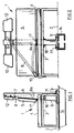
- FIG. 4 is a modified embodiment for the bow-like design of the column 6 is shown.
- this connection branches with the central connecting flange 9 screwed to the vehicle frame 2 column 6 in two sections 6a, 6b, which are then at their upper End again the headrests 12 and the top Articulation points 7 for those running outwards Wear seat belts 8.
- This also results a belt course according to FIG. 2.
- the column sections 6a and 6b can pass through the headrests 12 into the column areas, which in turn are inclined downwards 6 'to be continued. These can then be in the seat frame 3 open, or, if appropriate here Vehicle frame or a corresponding stable vehicle floor is present, even up to there continue downwards and again with a connecting flange 9 '- similar to Fig. 3 - screwed become.
- FIG. 5 is a simplified structure of the seat frame 3 shown. Here run from the bottom End of the column 6 from basket-shaped or radiating several diagonal struts 13 to the seat 4, so that this means no additional support feet for the seat frame 3 are required. This is also the Area under the seat 1 for cleaning purposes particularly accessible.
Abstract
Description
Die Erfindung betrifft eine Sitzbank für Kraftfahrzeuge, insbesondere Wohnmobile, bestehend aus einem Sitzbankgestell mit Sitzfläche und Sitzlehne für wenigstens zwei Personen, wobei das Sitzbankgestell am Fahrzeugboden/-rahmen angeordnet ist und eine Halterungsvorrichtung für die beiden Sicherheitsgurte aufweist, wie in der US-A-3,885,810 gezeigt.The invention relates to a seat for motor vehicles, in particular motorhomes consisting of a seat frame with seat and backrest for at least two people, the seat frame is arranged on the vehicle floor / frame and a Bracket for the two seat belts as shown in US-A-3,885,810.
Bei derartigen Sitzbänken für Kraftfahrzeuge, insbesondere im Wohnmobilbereich, werden häufig noch Beckengurte als Sicherheitsgurte verwendet (Zweipunktgurte), obwohl sich im PKW-Bereich längst der Dreipunktgurt als optimale Rückhaltevorrichtung durchgesetzt hat. Ein Grund liegt darin, daß die Sitzbankgestelle für eine Anlenkung von Dreipunktgurten, insbesondere mit dem oberen Anlenkpunkt (Gurtumlenkpunkt) keine ausreichende Festigkeit aufweisen. Eine Anlenkung der Sicherheitsgurte, wie im PKW-Bereich üblich, an der B- oder C-Säule der Kraftfahrzeugkarosserie, kommt aus zweierlei Gründen nicht in Betracht. Häufig ist nämlich die Sitzbank von einer Karosserie-Seitenwand abgerückt angeordnet, um für den Wohnbereich des Wohnmobiles genügend Durchgangsmöglichkeiten zu schaffen. Somit müßte der obere Anlenkpunkt für die zentrale Sitzposition über eine weite Strecke von etwa 1 m bis zu dem nächstliegenden Fahrzeugholm geführt werden. Der zweite Grund liegt darin, daß bei Wohnmobilen häufig nur Kunststoffaufbauten ohne besonders starre Karosseriestruktur auf den Fahrzeugrahmen aufgebaut werden, so daß bei einer Anlenkung an diese Aufbauten die erforderliche Unfallsicherheit, insbesondere die Ausreißfestigkeit des oberen Um-/Anlenkpunktes nicht gegeben ist. Auch die von verschiedenen Vans bekannte Lösung, wonach der obere Anlenkpunkt der Sicherheitsgurte im Deckenbereich (Dachhimmel) angeordnet ist, ist für Wohnmobile selbst nicht praktikabel, da eine ausreichende Stehhöhe und somit ein großer Abstand zwischen Sitzbank und Fahrzeugdach gefordert wird.In such seats for motor vehicles, in particular in the camper area, are often still Lap belts used as seat belts (two-point belts), although in the passenger car sector the Three-point belt enforced as an optimal restraint Has. One reason is that the bench frames for a linkage of three-point belts, especially with the upper articulation point (belt deflection point) do not have sufficient strength. A linkage of the seat belts, as in the car sector usual, on the B or C pillar of the motor vehicle body, does not come in for two reasons Consideration. The bench is often one Body side panel set back to order for the living area of the mobile home has enough passageways to accomplish. So the upper pivot point for the central seating position above a long distance of about 1 m to the closest one Vehicle spar are guided. The second The reason is that motorhomes are often only Plastic structures without a particularly rigid body structure be built on the vehicle frame, so that the necessary when articulated to these structures Accident safety, especially the pull-out strength of the upper pivot point is. Also the solution known from different vans, after which the upper pivot point of the seat belts in the Ceiling area (headlining) is arranged for Motorhomes themselves are not practical because they are adequate Standing height and thus a large distance between Seat and vehicle roof is required.
Aus der DE 93 02 831 U1 ist eine Sitzbank mit einer Vertikalstütze bekannt, die am Bodenteil des Fahrzeugchassis befestigt ist. Diese Vertikalstütze ist jedoch seitlich von der Sitzlehne und durch eine horizontal verlaufende Quertraverse zusätzlich abgestützt. Zudem ist hierbei an dem Sitzbankgestell nur ein Sicherheitsgurt vollständig angeordnet, während der obere Anlenkpunkt des zweiten Sicherheitsgurtes an einer Seitenwand des Fahrzeuges angeordnet ist. Dadurch ist eine stabile Außen-Karosserie erforderlich, was jedoch bei Wohnmobilen mit Kunststoff-Karosserie im allgemeinen nicht der Fall ist. Zudem ist hierdurch die Anordnung der Sitzbank konstruktiv festgelegt und kann nicht von dem oberen Gurt-Anlenkpunkt für den äußeren Sitzplatz wegverschoben werden, wie dies gerade für die Wohnmobilproduktion mit variabler und oft unterschiedlicher Sitzbankanordnung wünschenswert wäre.From DE 93 02 831 U1 a bench with a vertical support known, the Bottom part of the vehicle chassis is attached. This vertical support is however to the side of the seat back and thanks to a horizontal crossbar supported. In addition, this is on the seat frame only one seat belt fully arranged, during the upper pivot point of the second seat belt arranged on a side wall of the vehicle is. This is a stable outer body required, however, for motorhomes with a plastic body generally not. In addition, the arrangement of the seat is constructive fixed and can not from the upper strap pivot point moved away for the outer seat be like this just for RV production with variable and often different seating arrangements would be desirable.
Die DE 79 23 386 beschreibt einen Einzelsitz, wobei dreieckförmig angeordnete Verstärkungsstreben an dem Sitzunterteil angelenkt sind.DE 79 23 386 describes a single seat, with triangular reinforcing struts are hinged to the seat bottom.
Aus der DE 21 13 579 ist eine Halterungsvorrichtung für Sicherheitseinrichtungen bekannt, wobei Stützstreben direkt am Fahrzeugboden befestigt sind. Hierbei ist jedoch eine zusätzliche Querstrebe zur Verankerung an den seitlichen Rahmenholmen vorhanden.DE 21 13 579 is a mounting device known for safety devices, with support struts are attached directly to the vehicle floor. However, here is an additional cross strut for anchoring available on the side frame bars.
Aus der US 2,740,642 und der DE 27 47 398 sind Rückhaltesysteme mit aufrechten Rohren hinter den beiden Vordersitzen bekannt, wobei die Rohre zur zusätzlichen Befestigung zwischen Fahrzeugboden und Fahrzeugdach festgeklemmt oder mittels eines Drahtseiles befestigt werden. Dies macht einen stabilen Dachaufbau erforderlich, der bei Wohnmobilen im allgemeinen nicht vorhanden ist.From US 2,740,642 and DE 27 47 398 Restraint systems with upright tubes behind the known two front seats, the tubes for additional attachment between the vehicle floor and Clamped vehicle roof or using a wire rope be attached. This makes a stable one Roof structure required, that of motorhomes in general is not present.
Die DE 91 14 531 befaßt sich mit einem Verankerungsgestell für Sitzbänke, das durch entsprechende Verstrebungen ausgesteift ist. Hierbei sind jedoch die üblichen Zweipunkt-(Becken-)Gurte vorgesehen.DE 91 14 531 is concerned with an anchoring frame for benches, by appropriate Bracing is stiffened. Here, however, are the usual two-point (pelvic) belts provided.
Die DE 40 03 941 bezieht sich auf eine Sicherheitsgurtanordnung für die Rücksitze, wobei der obere Anlenkpunkt des Dreipunktgurtes hinter der Rücksitzanlage an einem feststehenden Bauteil befestigt ist.DE 40 03 941 relates to a seat belt arrangement for the rear seats, the upper one Articulation point of the three-point belt behind the rear seat system is attached to a fixed component.
Die US 3,451,719 zeigt lediglich eine hinter einer Sitzbank quer verlaufende Stange zum Straffen von Beckengurten.US 3,451,719 shows only one behind one Bench cross bar for tightening Lap belts.
Die US 2,833,554 beschreibt ein Aufprall-Sicherheitssystem, wobei vor der Brust und den Knien des Fahrers eine Prallplatte vorgesehen ist, die an einer zentralen, am Karosseriedach und Boden befestigten Stange gelagert ist.US 2,833,554 describes an impact safety system, being in front of the chest and knees of the Driver is provided a baffle plate on a central, attached to the body roof and floor Rod is stored.
Die US 2,891,804 befaßt sich mit einer Abstützvorrichtung für einen schräg verlaufenden Zweipunktgurt, wobei eine Säule am Dach des Fahrzeugs befestigt ist und zudem noch eine zusätzliche Strebe im Dach eingezogen ist.US 2,891,804 is concerned with a support device for an oblique two-point belt, a pillar is attached to the roof of the vehicle and also pulled in an additional strut in the roof is.
Die GB 2 102 743 befaßt sich mit einer Halterung
für Rollstuhlfahrer in Bussen, wobei die Säulenstangen
wiederum zwischen Boden und Dach des Bodens verspannt
werden.
Demzufolge liegt der Erfindung die Aufgabe zugrunde, eine Sitzbank für Kraftfahrzeuge, insbesondere Wohnmobile zu schaffen, die die Voraussetzungen zur Anwendung von Dreipunktgurten und damit eine erhöhte Unfallsicherheit ermöglicht, sowie eine einfache, weitgehend frei wählbare Befestigungsmöglichkeit im Fahrzeug bietet.The object of the invention is accordingly based, a seat for motor vehicles, in particular To create campers that meet the requirements for the use of three-point belts and thus one Enables increased accident safety, as well as a simple, largely freely selectable mounting option in the vehicle.
Diese Aufgabe wird gelöst durch eine Sitzbank mit
den Merkmalen des Patentanspruches
1.This task is solved by using a bench
the features of the
Durch die Anordnung einer aufrechten Säule an der Sitzlehne kann der obere Sicherheitsgurt-Anlenkpunkt für beide Sicherheitsgurte der beiden Sitzplätze an dieser sehr stabil ausgebildeten Säule angeordnet werden. Die nötige Festigkeit, insbesondere Biege-, Torsionsund Knickfestigkeit der Säule wird hierbei durch die direkte Verbindung am Fahrzeugboden/Fahrzeugrahmen mittels eines Anschlußflansches geschaffen, so daß die Krafteinleitung im Falle eines Unfalles unmittelbar in den Fahrzeugrahmen erfolgt. Bevorzugt ist hierbei der Anschlußflansch der Säule unmittelbar über einen Fahrzeug-Längsträger angeordnet. Durch diese freistehende Ausführung benötigt die Säule keinen zweiten Befestigungspunkt am Karosseriedach oder Seitenholmen, so daß die Sitzbank auf der Bodengruppe des Fahrzeuges nahezu an beliebigen Orten, insbesondere auch von den Seitenwänden abgerückt angeordnet werden kann.By placing an upright column on the Seat back can be the upper seat belt pivot point for both seat belts of the two seats on this very stable column. The necessary strength, especially bending, torsion and The column's kink resistance is determined by the direct connection to the vehicle floor / vehicle frame created by means of a connecting flange, so that the application of force in the event of an accident is immediate in the vehicle frame. It is preferred here the connecting flange of the column immediately above arranged a vehicle side member. Through this the column does not need a free-standing version second attachment point on the body roof or Side rails, so that the seat on the floor assembly of the vehicle almost anywhere, especially moved away from the side walls can be arranged.
Dabei ist für eine Sitzbank nur eine einzige zentrale Säule vorgesehen, von der dann die beiden oberen Um-/Anlenkpunkte für die beiden Sicherheitsgurte zu außenliegenden Gurtschlössern führen. In vorteilhafter Ausführung können dabei zugleich auch die Kopfstützen an dieser Säule angeordnet sein.It is only for a bench one central Column provided, of which then the two upper deflection / articulation points for the two seat belts lead to outside buckles. In advantageous Execution can also be carried out at the same time Headrests can be arranged on this column.
Weiterhin ist vorgesehen, daß das Sitzbankgestell, auf dem die Sitzfläche angeordnet ist, ebenfalls an der Säule befestigt ist, insbesondere angeschraubt ist. Hierdurch ergibt sich eine weitere Versteifung der Sitzbank-Struktur. Dabei wird das Sitzbankgestell dadurch gebildet, daß vom unteren Bereich der Säule aus strahlen- bzw. korbartig verlaufende Diagonalstreben angeordnet sind, die somit die Sitzfläche für die Sitzbank unterstützen und Halterungen für die Gurtschlösser bilden. Hierdurch kann erreicht werden, daß nach Lösen des Anschlußflansches für die Säule die gesamte Sitzbankgruppe leicht aus dem Fahrzeug ausgebaut werden kann. Der Anschlußflansch ist bevorzugt als unmittelbar über dem Fahrzeuglängsträger liegende Flanschplatte ausgebildet, die mittels Schraubverbindungen oder sonstigen Schnellverschlüssen rasch lösbar ist, also daß verschiedene Einbauorte für die Säule und die zugehörige Sitzbankgruppe innerhalb der Fahrzeuge gewählt werden können. Dies ist insbesondere vorteilhaft bei der Produktion, da für verschiedene Modelle die gleiche Sitzbank an verschiedenen Einbauvarianten verwendet werden kann.It is also provided that the seat frame, on which the seat is arranged, also on the Column is attached, in particular screwed. This results in a further stiffening of the seat structure. The bench frame formed by the fact that from the lower area of the Column made of radiating or basket-like diagonal struts are arranged, which is the seat for support the seat and brackets for the buckles form. In this way it can be achieved that after loosening the connection flange for the column Entire seat group easily removed from the vehicle can be. The connecting flange is preferred as lying directly above the vehicle side member Flange plate formed by means of screw connections or other quick release fasteners is that different installation locations for the column and the associated seat group within the vehicles can be chosen. This is particularly so advantageous in production because for different Models the same seat on different installation variants can be used.
Weitere vorteilhafte Ausgestaltungen der Erfindung sind Gegenstand der Unteransprüche.Further advantageous embodiments of the invention are the subject of the subclaims.
Nachfolgend werden mehrere Ausführungsbeispiele anhand der Zeichnungen näher erläutert und beschrieben.Below are several embodiments explained in more detail with reference to the drawings and described.
Es zeigen:
- Fig. 1
- eine schematische Seitenansicht des Grundaufbaus einer Sitzbank für Kraftfahrzeuge, insbesondere Wohnmobile;
- Fig. 2
- eine Vorderansicht der Sitzbank gemäß Fig. 1;
- Fig. 3
- eine abgewandelte Ausführungsform mit einer rohrförmigen Ausbildung der SitzbankSäule;
- Fig. 4
- eine weitere Ausführungsform der Sitzbank mit schematischer Darstellung der Einbausituation in einem Wohnmobil;
- Fig. 5
- eine besonders einfache Ausführungsform
der Sitzbank, insbesondere des Sitzbankgestells
gemäß
Patentanspruch 1.
- Fig. 1
- a schematic side view of the basic structure of a bench for motor vehicles, in particular motor homes;
- Fig. 2
- a front view of the seat of FIG. 1;
- Fig. 3
- a modified embodiment with a tubular design of the bench column;
- Fig. 4
- a further embodiment of the seat with a schematic representation of the installation situation in a mobile home;
- Fig. 5
- a particularly simple embodiment of the seat, in particular the seat frame according to
claim 1.
In Fig. 1 ist eine Seitenansicht auf eine Sitzbank 1
dargestellt, die auf einem Fahrzeugboden 2 stehend
befestigt ist. Die Sitzbank 1 besteht im wesentlichen
aus einem Sitzbankgestell 3, einer Sitzfläche 4 für zwei
Personen und einer sich daran rechtwinklig anschließenden,
in etwa flächengleichen Sitzlehne 5. Von
wesentlicher Bedeutung ist die Anordnung einer aufrechten
Säule 6 an der Rückseite der Sitzlehne 5, wobei
an dem oberen Endbereich der Säule 6 je ein oberer
Sicherheitsgurt-Anlenkpunkt 7 vorgesehen ist (vgl.
auch Fig. 2). Unter "Anlenkpunkt" 7 soll hierbei auch ein
Umlenkpunkt z. B. als Sicherheitsgurt-Umlenkbügel
verstanden werden.1 is a side view of a
Von wesentlicher Bedeutung ist weiterhin ein am
unteren Ende der Säule 6 vorgesehener Anschlußflansch
9 zur Verbindung der Säule 6 mit dem Fahrzeugboden
bzw. Fahrzeugrahmen 2. Dieser
Anschlußflansch 9 ist bevorzugt als relativ großflächige
Flanschplatte ausgebildet, die mit der Säule 6 fest verbunden,
insbesondere verschweißt ist und mit dem
Fahrzeugboden 2, insbesondere mit einem darunter
verlaufenden Rahmenträger (im allgemeinen Längsträger
14) mittels Schraubverbindungen 11 lösbar befestigt
ist. Die Säule 6 ist bevorzugt als Hohlprofil-Kastenträger
ausgebildet und weist einen sich nach
oben hin verjüngenden Querschnitt auf. Durch letztere
Maßnahme wird zum einen eine Anpassung an die Neigung
der Sitzlehne 5 erreicht, sowie eine besonders
hohe Formsteifigkeit bei Belastungen, wie sie bei einem
Unfall auf den Sicherheitsgurt 8 bzw. den oberen
Anlenkpunkt 7 auftreten. Zum anderen wird durch das
Hohlprofil der Säule 6 erreicht, daß die Gurtrolle 8a -
wie angedeutet -in einfacher Weise in die Säule 6 eingesetzt
werden kann. An dem oberen Anlenkpunkt 7
kann dabei auch eine Gurthöhenverstellung vorgesehen
sein, wie dies aus dem PKW-Bereich bekannt ist.An am is still essential
provided at the bottom end of the
Der Sicherheitsgurt 8 kann beim Anschnallen von
dem oberen Anlenkpunkt 7 an der Säule 6 herabgezogen
werden und an das hier außen liegende Gurtschloß
10 eingesteckt werden. Vom Gurtschloß 10 führt dann
der Beckenteil des Sicherheitsgurtes 8 zum unteren
Anlenkpunkt 17, der ebenfalls in bevorzugter Ausführung
direkt an der Säule 6 im Bereich zwischen der Sitzfläche
4 und der Sitzlehne 5 angeordnet ist. Da der
untere Anlenkpunkt 17 des Sicherheitsgurtes 8 im allgemeinen
jedoch geringfügigeren Beanspruchungen
als der obere Anlenkpunkt 7 ausgesetzt ist, könnte dieser
untere Anlenkpunkt 17 des Sicherheitsgurtes 8
auch an dem rahmenartigen Sitzbankgestell 3 angeordnet
sein.The
Von besonderer Bedeutung ist auch, daß die Kopfstützen
12 in besonders stabiler Weise an der Säule 6,
wie hier über horizontal verlaufende, nicht näher
bezeichnete Streben befestigt werden können. Somit
sind in der Sitzlehne 5 selbst keine Halterungen oder
Verstrebungen für die Kopfstützen 12 mehr nötig.It is also of particular importance that the
Es sei auch darauf hingewiesen, daß
das Sitzbankgestell 3, auf dem die Sitzfläche
4 angeordnet ist, ebenfalls mit der Säule 6 verbunden,
insbesondere verschraubt, wie dies durch die hier lediglich
schematisch eingezeichneten Winkellaschen 18 an
der Unterseite des Sitzbankgestelles 3 angedeutet ist.It should also be noted that
the
In Fig. 3 ist eine abgewandelte Ausführungsform
dargestellt, wobei die Säule 6 anstatt durch einen holmartigen
Profilträger durch zwei voneinander getrennte
Rohre 6 gebildet ist. Die übrigen Bauteile entsprechen
denen der Figuren 1 und 2, so daß hierzu dieselben
Bezugszeichen verwendet werden. Der Verlauf des
Dreipunkt-Sicherheitsgurtes 8 ist hierbei, wie angedeutet,
der gleiche wie in Fig. 2, nämlich mit einem bezüglich
der Sitzbank 1 mittigen oberen Anlenkpunkt 7,
einem seitlich außen liegenden Gurtschloß 10 und
einem wiederum mittig, bevorzugt an der Säule 6 angeordneten
unteren Anlenkpunkt 17. Bei dieser Ausführung
kann durch entsprechendes Biegen des Rohres
für die Säule 6 im oberen Bereich zugleich eine besonders
stabile Halterung für die Kopfstützen 12 geschaffen
werden. Der horizontale Bereich des Rohres 6 in
Nähe der Kopfstützen 12 kann jedoch zur Festigkeitserhöhung
auch noch weiter geführt werden zu einem
strichliert dargestellten Rohr 6', das dann eine etwa hufeisenförmige
oder bügelförmige Ausführung der Säule
6 ergibt. Es sei darauf hingewiesen, daß die hier strichliert
eingezeichnete Säule 6', ähnlich wie in der mittigen
Anordnung der Säule 6, ebenfalls mit einem Anschlußflansch
9' mit dem Fahrzeugboden 2 bzw. den Rahmenträgern
verbunden sein kann,
so daß
hierdurch der umgekehrte Sicherheitsgurtverlauf, wie
mit dem Bezugszeichen 8' bezeichnet, ausgehend von
einem oberen, seitlich außen liegenden Anlenkpunkt 7'
vorliegt.3 is a modified embodiment
shown, the
In Fig. 4 ist eine abgewandelte Ausführungsform für
die bügelartige Gestaltung der Säule 6 dargestellt. Hierbei
verzweigt sich die mit dem mittigen Anschlußflansch
9 an dem Fahrzeugrahmen 2 verschraubte Säule 6 in
zwei Teilabschnitte 6a, 6b, die dann an ihrem oberen
Ende wiederum die Kopfstützen 12 und die oberen
Anlenkpunkte 7 für die nach außen hin verlaufenden
Sicherheitsgurte 8 tragen. Hierdurch ergibt sich ebenfalls
ein Gurtverlauf gemäß Fig. 2. Die Säulenabschnitte
6a und 6b können jedoch durch die Kopfstützen 12 hindurch
in die dann wiederum abwärts geneigten Säulenbereiche
6' weitergeführt werden. Diese können dann in
das Sitzbankgestell 3 einmünden, oder, sofern hier entsprechende
Fahrzeugrahmen oder ein entsprechend
stabiler Fahrzeugboden vorhanden ist, auch bis dorthin
nach unten weitergeführt werden und wiederum mit
einem Anschlußflansch 9' - ähnlich wie in Fig. 3 - verschraubt
werden.4 is a modified embodiment for
the bow-like design of the
Zur besseren Darstellung ist hierbei ein Rahmenaufbau
20 eines Wohnmobiles angedeutet. Hieraus ist
ersichtlich, daß die Sitzbank und die Säule 6 keinerlei
Verbindungen zu der Seitenwand 20 (oder dem Karosseriedach)
benötigt, also im oberen Bereich freistehend
angeordnet ist, wodurch sich eine nahezu beliebige Plazierung
in Breiten- und Längsrichtung des Fahrzeuges
ergibt. Hierdurch kann die Sitzbank beispielsweise
unmittelbar neben Seitenfenstern aufgestellt werden.
Wie ersichtlich, ist bei der Ausführung mit zwei Längsträgern
14 die mittige Säule 6 über den Anschlußflansch
9 unmittelbar mit dem hier rechten Längsträger
14 verbunden. Es sind jedoch auch Karosserie-Aufbauten
bekannt, bei denen der Fahrzeugrahmen durch
mehrere nebeneinander mit Abstand verlaufende
Längsträger 14' (strichpunktiert dargestellt) gebildet ist.
In letzterem Falle kann es festigkeitsmäßig günstiger
sein, Anschlußflansche 9 zusätzlich an den beiden
äußeren Säulen 6' anzuordnen, da hierdurch eine bessere
Krafteinleitung bei Unfallsituationen möglich ist.Here is a frame structure for
In Fig. 5 ist ein vereinfachter Aufbau des Sitzbankgestelles
3 dargestellt. Hierbei verlaufen vom unteren
Ende der Säule 6 aus korbförmig oder strahlenförmig
mehrere Diagonalstreben 13 zur Sitzfläche 4, so daß
hierdurch keine zusätzlichen Abstützfüße für das Sitzbankgestell
3 erforderlich sind. Hierdurch ist auch der
unter der Sitzbank 1 befindliche Bereich für Reinigungszwecke
besonders gut zugänglich.5 is a simplified structure of the
Claims (7)
- A bench seat for motor vehicles, in particular camping cars, consisting of a frame-like bench seat frame (3) with seat (4) and back rest (5) being spaced apart from the vehicle floor (2) for at least two persons, with the bench seat frame (3) being arranged at the vehicle floor/chassis (2) and comprising the holding device for both three-point safety belts, wherein at said back rest (5) at least one upright column (6) is provided, comprising one top safety belt coupling point (7) each at its top end area and comprising a coupling flange (9) at its lower end for connection with the vehicle floor/chassis (2), wherein said column (6) is a supporting component part of said bench seat frame (3) and said bench seat frame (3) is detachably mounted at said column (6), in particular bolted, and wherein said bench seat frame (3) is formed by radially extending diagonal struts (13) emanating from the lower portion of the centrally arranged column (6).
- A bench seat according to claim 1, characterized in that said coupling flange (9) is formed as a flange plate being connected with said column (6), in particular welded, and being detachably mounted on said vehicle floor/chassis (2) by means of bolted connections (11).
- A bench seat according to claim 1 or 2, characterized in that said column (6) projects beyond the top edge of said back rest (5).
- A bench seat according to claim 3, characterized in that at least one head rest (12) is mounted at said column (6).
- A bench seat according to any of the claims 1 to 4, characterized in that said column (6) comprises an upwardly tapering cross-section.
- A bench seat according to claim 5, characterized in that said column (6) is formed as a hollow section box girder.
- A bench seat according to any of the claims 1 to 6, characterized in that said coupling flange (9) of said column (6) is directly arranged above a longitudinal beam (14) of the vehicle.
Applications Claiming Priority (3)
| Application Number | Priority Date | Filing Date | Title |
|---|---|---|---|
| DE4316930A DE4316930C2 (en) | 1993-05-19 | 1993-05-19 | Seat for motor vehicles, in particular mobile homes |
| DE4316930 | 1993-05-19 | ||
| PCT/EP1994/001607 WO1994026553A1 (en) | 1993-05-19 | 1994-05-18 | Bench seat for motor vehicles, in particular camping cars |
Publications (3)
| Publication Number | Publication Date |
|---|---|
| EP0765252A1 EP0765252A1 (en) | 1997-04-02 |
| EP0765252B1 EP0765252B1 (en) | 1999-01-07 |
| EP0765252B2 true EP0765252B2 (en) | 2002-06-12 |
Family
ID=6488571
Family Applications (1)
| Application Number | Title | Priority Date | Filing Date |
|---|---|---|---|
| EP94918337A Expired - Lifetime EP0765252B2 (en) | 1993-05-19 | 1994-05-18 | Bench seat for motor vehicles, in particular camping cars |
Country Status (7)
| Country | Link |
|---|---|
| US (1) | US5868452A (en) |
| EP (1) | EP0765252B2 (en) |
| AT (1) | ATE175385T1 (en) |
| AU (1) | AU684085B2 (en) |
| DE (2) | DE4316930C2 (en) |
| ES (1) | ES2129643T3 (en) |
| WO (1) | WO1994026553A1 (en) |
Families Citing this family (46)
| Publication number | Priority date | Publication date | Assignee | Title |
|---|---|---|---|---|
| DE9318743U1 (en) * | 1993-12-08 | 1994-05-11 | Biese Gabriela Maria | Seat for motorhomes, vans, etc. with at least two seat parts and at least two backrest parts as well as a device for receiving the upper point of the shoulder belt from at least one three-point restraint system |
| IT1267995B1 (en) * | 1994-01-27 | 1997-02-20 | Sepi Spa | FRONT SEATING ARRANGEMENT FOR LIGHT TRUCKS, VANS OR SIMILAR. |
| DE29507216U1 (en) * | 1995-04-29 | 1995-06-29 | Schnierle & Partner Gmbh M | Seat for passengers |
| EP0854795A1 (en) * | 1995-11-07 | 1998-07-29 | C.A.B. Voertuigtechniek N.V. | Securing means for a vehicle seat |
| NL1001595C2 (en) * | 1995-11-07 | 1997-05-13 | C A B Voertuigtechniek N V | Seat securing assembly for passenger vehicles, e.g. buses |
| DE19544014A1 (en) * | 1995-11-27 | 1997-05-28 | Aguti Prod Entw & Design Gmbh | Folding bench |
| WO1998051527A2 (en) * | 1997-05-14 | 1998-11-19 | Biese, Gabriela-Maria | Seat substructure for a bench seat or an individual seat in a motor vehicle |
| DE19754311B4 (en) * | 1997-06-10 | 2007-09-06 | Ewald Witte Gmbh & Co Kg | Backrest with headrest on vehicle seats |
| DE19745634C2 (en) * | 1997-10-16 | 2002-02-07 | Vogel Ind Gmbh | Passenger seat with column for belt fastening |
| DE19800071A1 (en) * | 1998-01-02 | 1999-07-08 | Volkswagen Ag | Restraint with a seat belt |
| DE19814845B4 (en) * | 1998-04-02 | 2006-11-09 | Volkswagen Ag | Safety belt arrangement for a double-seat arrangement of a vehicle |
| US6312056B1 (en) * | 1998-06-16 | 2001-11-06 | Gary H. Murphy | Occupant restraint system with compartmentalization |
| US6533320B1 (en) | 1999-03-17 | 2003-03-18 | Magna Seating Systems Inc. | Automotive seat belt restraint assembly |
| FR2795026B1 (en) * | 1999-06-17 | 2001-08-31 | Renault | SEAT ASSEMBLY FOR MOUNTING ON A MOTOR VEHICLE FLOOR |
| JP3714039B2 (en) * | 1999-06-18 | 2005-11-09 | 日産自動車株式会社 | Seat belt integrated seat |
| DE19939548B4 (en) * | 1999-08-20 | 2009-07-23 | Volkswagen Ag | Motor vehicle in the manner of a flatbed with safety belt attachment to a cabin rear wall |
| DE10059043A1 (en) * | 2000-11-28 | 2002-05-29 | Aguti Prod Entw & Design Gmbh | Seat bench for vehicles, esp. camper vans has divided seat with one seat part and connected arm rest moveable at right angles to travel direction |
| US7597395B2 (en) | 2002-01-04 | 2009-10-06 | Honda Giken Kogyo Kabushiki Kaisha | Vehicle seat |
| FR2839930B1 (en) * | 2002-05-23 | 2005-01-14 | Compin | SEATS FOR PUBLIC TRANSPORT VEHICLES |
| DE10311281B3 (en) * | 2003-03-14 | 2004-10-07 | Wilhelm Karmann Gmbh | Safety belt arrangement for car seats arranged next to each other has belts which are guided across roller devices |
| GB0315303D0 (en) * | 2003-06-30 | 2003-08-06 | Constant Developments Ltd | Seating apparatus for use on a vehicle having a storage area normally used for carrying cargo |
| US7438354B2 (en) * | 2005-03-17 | 2008-10-21 | Freedman Seating Company | Integrated seatbelt in a cantilevered stowable seat with an improved dump locking mechanism |
| DE102006007383B4 (en) * | 2006-02-17 | 2008-04-30 | Unex-Metall Gmbh | Restraint system for a bench in the living area of a mobile home |
| US9010865B2 (en) * | 2007-01-05 | 2015-04-21 | Ford Global Technologies, Llc | Automotive vehicle seat system |
| US20080164732A1 (en) * | 2007-01-05 | 2008-07-10 | Ford Global Technologies, Llc | Automotive vehicle seat system |
| US8628135B2 (en) * | 2007-01-05 | 2014-01-14 | Ford Global Technologies, Llc | Automotive vehicle seat system |
| FR2914597B1 (en) * | 2007-04-03 | 2009-05-22 | Renault Sas | BENCH FOR UTILITY VEHICLE WITH A STORAGE SYSTEM |
| FR2962699B1 (en) | 2010-07-13 | 2016-09-30 | Renault Sa | BENCH FOR UTILITY VEHICLE WITH USEFUL LOADING SPACE |
| DE202010016271U1 (en) * | 2010-12-07 | 2011-04-07 | Hymer Ag | Seat in longitudinal bench |
| DE102011010705A1 (en) * | 2011-02-09 | 2012-08-16 | Gm Global Technology Operations, Llc | Passenger car without B-pillar |
| US8579349B1 (en) * | 2012-01-23 | 2013-11-12 | Phillip E. Schlangen | Headrest assembly |
| JP6305892B2 (en) * | 2014-09-30 | 2018-04-04 | 本田技研工業株式会社 | Seat belt mounting structure for rough terrain vehicles |
| DE102016106794A1 (en) * | 2016-04-13 | 2017-10-19 | Aguti Produktentwicklung & Design Gmbh | Device for attaching a safety belt system |
| DE202016102135U1 (en) | 2016-04-22 | 2017-07-27 | Alois Kober Gmbh | Gurtbockanordnung |
| DE102016124934A1 (en) * | 2016-12-20 | 2018-06-21 | Aguti Produktentwicklung & Design Gmbh | Vehicle seat with a safety belt system |
| DE102017103778A1 (en) | 2017-02-23 | 2018-08-23 | Aguti Produktentwicklung & Design Gmbh | Belt frame for a vehicle seat or a vehicle seat |
| DE102017109466A1 (en) * | 2017-05-03 | 2018-11-08 | Aguti Produktentwicklung & Design Gmbh | Device for arranging a passenger restraint system in a vehicle |
| DE102018116807A1 (en) * | 2018-07-11 | 2020-01-16 | HYMER GmbH & Co. KG | Camper |
| US10870379B1 (en) | 2019-08-22 | 2020-12-22 | Aguti Produktentwicklung & Design Gmbh | Belt framework for a vehicle seat or a vehicle-seat bench |
| US11433945B2 (en) | 2019-11-01 | 2022-09-06 | Aguti Produktentwicklung & Design Gmbh | Device for arranging a passenger restraint system in a vehicle |
| US11305678B2 (en) * | 2020-08-20 | 2022-04-19 | Aguti Produktentwicklung & Design Gmbh | Belt mount for a vehicle seat or a vehicle bench seat and vehicle seat arrangement |
| FR3119805B1 (en) | 2021-02-18 | 2023-02-24 | Faurecia Sieges Dautomobile | vehicle seat |
| DE102021123829A1 (en) | 2021-09-15 | 2023-03-16 | Aguti Produktentwicklung & Design Gmbh | Seat assembly base, vehicle floor structure and vehicle |
| DE102022102686A1 (en) | 2022-02-04 | 2023-08-10 | Aguti Produktentwicklung & Design Gmbh | Belt frame for a vehicle seat |
| DE102022102684A1 (en) * | 2022-02-04 | 2023-08-10 | Aguti Produktentwicklung & Design Gmbh | Belt frame for a vehicle seat |
| DE102022117463A1 (en) * | 2022-07-13 | 2024-01-18 | HYMER GmbH & Co. KG | Recreational vehicle and seatbelt assembly |
Family Cites Families (26)
| Publication number | Priority date | Publication date | Assignee | Title |
|---|---|---|---|---|
| US2891804A (en) * | 1954-12-16 | 1959-06-23 | John S Frayne | Vehicle body rigidifying device and mounting for passenger harness |
| US2740642A (en) * | 1955-05-26 | 1956-04-03 | Walter A Atwood | Automobile passenger crash protector |
| US2833554A (en) * | 1955-08-17 | 1958-05-06 | Ricordi Giorgio | Apparatus for the safety and protection of automobile passengers |
| US3451719A (en) * | 1967-11-24 | 1969-06-24 | Gen Motors Corp | Seat anchorage |
| DE2113579C2 (en) * | 1971-03-20 | 1982-08-26 | Keiper Recaro GmbH & Co, 7312 Kirchheim | Device for fastening safety devices in a vehicle |
| US3762505A (en) * | 1971-12-01 | 1973-10-02 | S Morse | Device for reducing severity of impact forces |
| US3885810A (en) * | 1972-01-10 | 1975-05-27 | John J Chika | Seat supporting structure for fast moving vehicles |
| JPS5079126U (en) * | 1973-11-22 | 1975-07-09 | ||
| DE2747398A1 (en) * | 1976-10-22 | 1978-05-03 | Stig Martin Lindblad | Vehicle seat back rest retainer - has back rest top connected by webbing to take-up spool with blocking device |
| DE7923386U1 (en) * | 1979-08-16 | 1980-04-30 | Recaro Gmbh & Co, 7312 Kirchheim | SAFETY SEAT FOR VEHICLES |
| US4350369A (en) * | 1980-09-08 | 1982-09-21 | Chika John J | Vehicle occupant restraining devices |
| GB2102743B (en) * | 1981-07-24 | 1985-09-04 | Fretwell Limited P And J | Safety devices for wheelchairs |
| DE8526894U1 (en) * | 1985-09-20 | 1985-12-12 | Felten, Christian | Mounting bracket for harness attachment with integrated strut brace in passenger cars |
| AU561233B2 (en) * | 1986-09-15 | 1987-04-23 | Peter Leonard Smith | Child's seat anchorage bar |
| AU562352B3 (en) * | 1987-05-21 | 1987-07-21 | Kenneth Hall | Collapsible child restraint anchorage post |
| DE3813557A1 (en) * | 1988-04-22 | 1989-11-02 | Porsche Ag | Vehicle seat with an associated seat belt system |
| DE3822461A1 (en) * | 1988-07-02 | 1990-01-04 | Daimler Benz Ag | Head support for vehicle seats |
| HU210836B (en) * | 1989-09-06 | 1995-08-28 | Ikarusz Jarmuegyarto Rt | Auxiliary framework for keeping suspended passenger seats advantageously for buses |
| DE4003941A1 (en) * | 1990-02-09 | 1991-08-14 | Porsche Ag | SAFETY BELT ARRANGEMENT FOR THE REAR SEAT SYSTEM OF A MOTOR VEHICLE |
| US5328231A (en) * | 1991-02-21 | 1994-07-12 | American Seating Company | Equal access seating |
| FR2675748A1 (en) * | 1991-04-25 | 1992-10-30 | Peugeot | ERGONOMIC INDIVIDUAL SEAT FOR MOTOR VEHICLE COMPLETELY INTEGRATING A RESTRAINT SYSTEM AND MOTOR VEHICLE EQUIPPED WITH TWO OF THESE SEATS AT THE FRONT PLACES. |
| DE9114531U1 (en) * | 1991-11-22 | 1992-12-17 | Hymer Ag, 7967 Bad Waldsee, De | |
| US5362129A (en) * | 1992-09-29 | 1994-11-08 | Tachi-S Co., Ltd. | Structure of a casing for headrest stay |
| DE9302831U1 (en) * | 1993-02-26 | 1993-04-22 | Dehler Yachtbau Gmbh, 5778 Meschede, De | |
| DE9314859U1 (en) * | 1993-09-30 | 1994-01-05 | Sportscraft Freizeitprodukte G | Folding bench seat with restraint system, especially for campers |
| US5452941A (en) * | 1994-07-19 | 1995-09-26 | Hoover University, Inc. | Flat seat belt retractor |
-
1993
- 1993-05-19 DE DE4316930A patent/DE4316930C2/en not_active Revoked
-
1994
- 1994-05-18 US US08/557,160 patent/US5868452A/en not_active Expired - Fee Related
- 1994-05-18 WO PCT/EP1994/001607 patent/WO1994026553A1/en active IP Right Grant
- 1994-05-18 AT AT94918337T patent/ATE175385T1/en not_active IP Right Cessation
- 1994-05-18 AU AU69702/94A patent/AU684085B2/en not_active Ceased
- 1994-05-18 EP EP94918337A patent/EP0765252B2/en not_active Expired - Lifetime
- 1994-05-18 ES ES94918337T patent/ES2129643T3/en not_active Expired - Lifetime
- 1994-05-18 DE DE59407609T patent/DE59407609D1/en not_active Expired - Fee Related
Also Published As
| Publication number | Publication date |
|---|---|
| AU684085B2 (en) | 1997-12-04 |
| US5868452A (en) | 1999-02-09 |
| DE4316930C2 (en) | 1995-06-14 |
| DE4316930A1 (en) | 1993-10-07 |
| DE59407609D1 (en) | 1999-02-18 |
| EP0765252B1 (en) | 1999-01-07 |
| EP0765252A1 (en) | 1997-04-02 |
| ES2129643T3 (en) | 1999-06-16 |
| ATE175385T1 (en) | 1999-01-15 |
| AU6970294A (en) | 1994-12-12 |
| WO1994026553A1 (en) | 1994-11-24 |
Similar Documents
| Publication | Publication Date | Title |
|---|---|---|
| EP0765252B2 (en) | Bench seat for motor vehicles, in particular camping cars | |
| DE102004030215B4 (en) | Headrest for seats | |
| EP2505428B1 (en) | Belt fixture at the rear main tube of a backrest, ideally at the rear bottom foot | |
| EP0861165A1 (en) | Folding bench seat | |
| DE102007046535A1 (en) | Motor vehicle, in particular cabriolet, with a rollover protection device arranged behind the seats | |
| DE4213917C2 (en) | Backrest frame for a vehicle seat | |
| DE3022640C2 (en) | ||
| EP3539818B1 (en) | Belt frame for a vehicle seat or a bench seat and vehicle seating assembly | |
| EP0646503B1 (en) | Safety belt arrangement for the back seat of a vehicle | |
| EP3231665A1 (en) | Device for attaching a safety belt system | |
| EP1288113B1 (en) | Cabin for a utility vehicule | |
| DE4333463A1 (en) | Motor caravan with a fastening device for safety belts | |
| EP0683073A1 (en) | A partitioning device for protecting the compartment behind the front or rear seat of a motor vehicle | |
| EP0635405B1 (en) | Automotive camper with a seatbelt fastening system | |
| DE102004004376B3 (en) | Fixing device for child seat in vehicle has fixing elements with seat traverse fixed to one end, and other end fitted to structural side component | |
| DE2547630C3 (en) | Cab for trucks | |
| DE10302212B4 (en) | Motor vehicle and method for its production | |
| DE102022119832A1 (en) | Harness rack for attaching a seat belt system for a recreational vehicle and recreational vehicle | |
| DE102019122979A1 (en) | Seat frame for a vehicle seat arrangement | |
| EP0562302B1 (en) | Support frame for a stretcher | |
| EP1048555B1 (en) | Restraining structure for a bunk bed in commercial vehicles or campers | |
| DE19939548B4 (en) | Motor vehicle in the manner of a flatbed with safety belt attachment to a cabin rear wall | |
| DE102022110610A1 (en) | Recreational vehicle, especially motor home, and seatbelt assembly | |
| DE3029392A1 (en) | Rear step for van - has padded cross-member on adjustable brackets on rear chassis frame | |
| DE1154361B (en) | Fastening of storage areas made of textiles or the like in a motor vehicle |
Legal Events
| Date | Code | Title | Description |
|---|---|---|---|
| PUAI | Public reference made under article 153(3) epc to a published international application that has entered the european phase |
Free format text: ORIGINAL CODE: 0009012 |
|
| 17P | Request for examination filed |
Effective date: 19951219 |
|
| AK | Designated contracting states |
Kind code of ref document: A1 Designated state(s): AT BE CH DE DK ES FR GB IT LI NL PT SE |
|
| 17Q | First examination report despatched |
Effective date: 19970825 |
|
| GRAG | Despatch of communication of intention to grant |
Free format text: ORIGINAL CODE: EPIDOS AGRA |
|
| GRAG | Despatch of communication of intention to grant |
Free format text: ORIGINAL CODE: EPIDOS AGRA |
|
| GRAH | Despatch of communication of intention to grant a patent |
Free format text: ORIGINAL CODE: EPIDOS IGRA |
|
| GRAH | Despatch of communication of intention to grant a patent |
Free format text: ORIGINAL CODE: EPIDOS IGRA |
|
| GRAA | (expected) grant |
Free format text: ORIGINAL CODE: 0009210 |
|
| AK | Designated contracting states |
Kind code of ref document: B1 Designated state(s): AT BE CH DE DK ES FR GB IT LI NL PT SE |
|
| PG25 | Lapsed in a contracting state [announced via postgrant information from national office to epo] |
Ref country code: SE Free format text: THE PATENT HAS BEEN ANNULLED BY A DECISION OF A NATIONAL AUTHORITY Effective date: 19990107 Ref country code: NL Free format text: LAPSE BECAUSE OF FAILURE TO SUBMIT A TRANSLATION OF THE DESCRIPTION OR TO PAY THE FEE WITHIN THE PRESCRIBED TIME-LIMIT Effective date: 19990107 Ref country code: GB Free format text: LAPSE BECAUSE OF FAILURE TO SUBMIT A TRANSLATION OF THE DESCRIPTION OR TO PAY THE FEE WITHIN THE PRESCRIBED TIME-LIMIT Effective date: 19990107 |
|
| REF | Corresponds to: |
Ref document number: 175385 Country of ref document: AT Date of ref document: 19990115 Kind code of ref document: T |
|
| REG | Reference to a national code |
Ref country code: CH Ref legal event code: EP |
|
| REF | Corresponds to: |
Ref document number: 59407609 Country of ref document: DE Date of ref document: 19990218 |
|
| ITF | It: translation for a ep patent filed |
Owner name: BUZZI, NOTARO&ANTONIELLI D'OULX |
|
| GBT | Gb: translation of ep patent filed (gb section 77(6)(a)/1977) |
Effective date: 19990222 |
|
| PG25 | Lapsed in a contracting state [announced via postgrant information from national office to epo] |
Ref country code: PT Free format text: LAPSE BECAUSE OF FAILURE TO SUBMIT A TRANSLATION OF THE DESCRIPTION OR TO PAY THE FEE WITHIN THE PRESCRIBED TIME-LIMIT Effective date: 19990407 Ref country code: DK Free format text: LAPSE BECAUSE OF FAILURE TO SUBMIT A TRANSLATION OF THE DESCRIPTION OR TO PAY THE FEE WITHIN THE PRESCRIBED TIME-LIMIT Effective date: 19990407 |
|
| ET | Fr: translation filed | ||
| PG25 | Lapsed in a contracting state [announced via postgrant information from national office to epo] |
Ref country code: LI Free format text: LAPSE BECAUSE OF NON-PAYMENT OF DUE FEES Effective date: 19990531 Ref country code: CH Free format text: LAPSE BECAUSE OF NON-PAYMENT OF DUE FEES Effective date: 19990531 Ref country code: BE Free format text: LAPSE BECAUSE OF NON-PAYMENT OF DUE FEES Effective date: 19990531 |
|
| REG | Reference to a national code |
Ref country code: ES Ref legal event code: FG2A Ref document number: 2129643 Country of ref document: ES Kind code of ref document: T3 |
|
| PLAV | Examination of admissibility of opposition |
Free format text: ORIGINAL CODE: EPIDOS OPEX |
|
| PLBQ | Unpublished change to opponent data |
Free format text: ORIGINAL CODE: EPIDOS OPPO |
|
| PLBI | Opposition filed |
Free format text: ORIGINAL CODE: 0009260 |
|
| PLAV | Examination of admissibility of opposition |
Free format text: ORIGINAL CODE: EPIDOS OPEX |
|
| PLBF | Reply of patent proprietor to notice(s) of opposition |
Free format text: ORIGINAL CODE: EPIDOS OBSO |
|
| BERE | Be: lapsed |
Owner name: AGUTI PRODUKTENTWICKLUNG & DESIGN G.M.B.H. Effective date: 19990531 |
|
| 26 | Opposition filed |
Opponent name: AL-KO KOBER GMBH MASCHINENFABRIK Effective date: 19991005 |
|
| REG | Reference to a national code |
Ref country code: CH Ref legal event code: PL |
|
| NLR1 | Nl: opposition has been filed with the epo |
Opponent name: AL-KO KOBER GMBH MASCHINENFABRIK |
|
| PLBF | Reply of patent proprietor to notice(s) of opposition |
Free format text: ORIGINAL CODE: EPIDOS OBSO |
|
| PLBF | Reply of patent proprietor to notice(s) of opposition |
Free format text: ORIGINAL CODE: EPIDOS OBSO |
|
| PGFP | Annual fee paid to national office [announced via postgrant information from national office to epo] |
Ref country code: GB Payment date: 20010516 Year of fee payment: 8 |
|
| PGFP | Annual fee paid to national office [announced via postgrant information from national office to epo] |
Ref country code: AT Payment date: 20010523 Year of fee payment: 8 |
|
| PGFP | Annual fee paid to national office [announced via postgrant information from national office to epo] |
Ref country code: NL Payment date: 20010531 Year of fee payment: 8 Ref country code: ES Payment date: 20010531 Year of fee payment: 8 |
|
| PLAW | Interlocutory decision in opposition |
Free format text: ORIGINAL CODE: EPIDOS IDOP |
|
| PLAW | Interlocutory decision in opposition |
Free format text: ORIGINAL CODE: EPIDOS IDOP |
|
| REG | Reference to a national code |
Ref country code: GB Ref legal event code: IF02 |
|
| PUAH | Patent maintained in amended form |
Free format text: ORIGINAL CODE: 0009272 |
|
| STAA | Information on the status of an ep patent application or granted ep patent |
Free format text: STATUS: PATENT MAINTAINED AS AMENDED |
|
| PG25 | Lapsed in a contracting state [announced via postgrant information from national office to epo] |
Ref country code: AT Free format text: LAPSE BECAUSE OF NON-PAYMENT OF DUE FEES Effective date: 20020518 |
|
| 27A | Patent maintained in amended form |
Effective date: 20020612 |
|
| AK | Designated contracting states |
Kind code of ref document: B2 Designated state(s): AT BE CH DE DK ES FR GB IT LI NL PT SE |
|
| NLR2 | Nl: decision of opposition | ||
| PG25 | Lapsed in a contracting state [announced via postgrant information from national office to epo] |
Ref country code: ES Free format text: LAPSE BECAUSE OF FAILURE TO SUBMIT A TRANSLATION OF THE DESCRIPTION OR TO PAY THE FEE WITHIN THE PRESCRIBED TIME-LIMIT Effective date: 20020923 |
|
| NLV1 | Nl: lapsed or annulled due to failure to fulfill the requirements of art. 29p and 29m of the patents act | ||
| ET3 | Fr: translation filed ** decision concerning opposition | ||
| GBV | Gb: ep patent (uk) treated as always having been void in accordance with gb section 77(7)/1977 [no translation filed] |
Effective date: 19990107 |
|
| PGFP | Annual fee paid to national office [announced via postgrant information from national office to epo] |
Ref country code: DE Payment date: 20080601 Year of fee payment: 15 |
|
| PGFP | Annual fee paid to national office [announced via postgrant information from national office to epo] |
Ref country code: IT Payment date: 20080527 Year of fee payment: 15 |
|
| PGFP | Annual fee paid to national office [announced via postgrant information from national office to epo] |
Ref country code: FR Payment date: 20080523 Year of fee payment: 15 |
|
| REG | Reference to a national code |
Ref country code: FR Ref legal event code: ST Effective date: 20100129 |
|
| PG25 | Lapsed in a contracting state [announced via postgrant information from national office to epo] |
Ref country code: FR Free format text: LAPSE BECAUSE OF NON-PAYMENT OF DUE FEES Effective date: 20090602 |
|
| PG25 | Lapsed in a contracting state [announced via postgrant information from national office to epo] |
Ref country code: DE Free format text: LAPSE BECAUSE OF NON-PAYMENT OF DUE FEES Effective date: 20091201 |
|
| PG25 | Lapsed in a contracting state [announced via postgrant information from national office to epo] |
Ref country code: IT Free format text: LAPSE BECAUSE OF NON-PAYMENT OF DUE FEES Effective date: 20090518 |