EP0764819B1 - Dispositif régulateur de débit d'air perfectionné - Google Patents
Dispositif régulateur de débit d'air perfectionné Download PDFInfo
- Publication number
- EP0764819B1 EP0764819B1 EP96401983A EP96401983A EP0764819B1 EP 0764819 B1 EP0764819 B1 EP 0764819B1 EP 96401983 A EP96401983 A EP 96401983A EP 96401983 A EP96401983 A EP 96401983A EP 0764819 B1 EP0764819 B1 EP 0764819B1
- Authority
- EP
- European Patent Office
- Prior art keywords
- flap
- channel
- upstream
- air flow
- air
- Prior art date
- Legal status (The legal status is an assumption and is not a legal conclusion. Google has not performed a legal analysis and makes no representation as to the accuracy of the status listed.)
- Expired - Lifetime
Links
- 238000011144 upstream manufacturing Methods 0.000 claims description 21
- 238000004378 air conditioning Methods 0.000 claims description 2
- 230000005484 gravity Effects 0.000 claims description 2
- 230000001105 regulatory effect Effects 0.000 description 6
- 230000033228 biological regulation Effects 0.000 description 3
- 238000009423 ventilation Methods 0.000 description 2
- 230000003750 conditioning effect Effects 0.000 description 1
- 230000032798 delamination Effects 0.000 description 1
- 230000001419 dependent effect Effects 0.000 description 1
- 230000009931 harmful effect Effects 0.000 description 1
- 238000000034 method Methods 0.000 description 1
- COCAUCFPFHUGAA-MGNBDDOMSA-N n-[3-[(1s,7s)-5-amino-4-thia-6-azabicyclo[5.1.0]oct-5-en-7-yl]-4-fluorophenyl]-5-chloropyridine-2-carboxamide Chemical compound C=1C=C(F)C([C@@]23N=C(SCC[C@@H]2C3)N)=CC=1NC(=O)C1=CC=C(Cl)C=N1 COCAUCFPFHUGAA-MGNBDDOMSA-N 0.000 description 1
- 230000000750 progressive effect Effects 0.000 description 1
- 238000005086 pumping Methods 0.000 description 1
Images


Classifications
-
- F—MECHANICAL ENGINEERING; LIGHTING; HEATING; WEAPONS; BLASTING
- F24—HEATING; RANGES; VENTILATING
- F24F—AIR-CONDITIONING; AIR-HUMIDIFICATION; VENTILATION; USE OF AIR CURRENTS FOR SCREENING
- F24F11/00—Control or safety arrangements
- F24F11/70—Control systems characterised by their outputs; Constructional details thereof
- F24F11/72—Control systems characterised by their outputs; Constructional details thereof for controlling the supply of treated air, e.g. its pressure
- F24F11/74—Control systems characterised by their outputs; Constructional details thereof for controlling the supply of treated air, e.g. its pressure for controlling air flow rate or air velocity
- F24F11/75—Control systems characterised by their outputs; Constructional details thereof for controlling the supply of treated air, e.g. its pressure for controlling air flow rate or air velocity for maintaining constant air flow rate or air velocity
Definitions
- the present invention relates to a device advanced air flow regulator usable in a ventilation system, air conditioning or the like, depending on the preamble of claim 1.
- the object of the present invention is to overcome these disadvantages of the known regulating device.
- Figure 1 is a schematic and cross-sectional view longitudinal of a compliant regulating device to the principles of the invention.
- Figure 2 is still a schematic view and in longitudinal section, but showing another mode of realization of this regulating device.
- Figure 3 is a view similar to the previous ones but schematically showing yet another embodiment of this device.
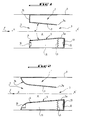
- Figure 4 is still a schematic view of a another embodiment of a regulating device according to this invention.
- Figure 5 is a perspective view of a device regulator according to this invention and whose structure corresponds to that shown schematically on the figure 1.
- Figure 6 is a sectional view along substantially line VI-VI of Figure 5.
- Figure 7 is a perspective view of another mode realization of regulating device according to this invention and corresponding substantially to that shown schematically in Figure 3.
- a device air flow regulator essentially comprises a body 1 provided with an inlet constituting the upstream part 2 of the body 1 and of a outlet constituting the downstream part 3 of the body, this body therefore allowing the next air passage the arrows marked F and whose flow will be automatically regulated.
- the body 1 forms a conduit which can be by example mounted in a pipe belonging to a ventilation or conditioning system of air, this pipe being marked at 4 on the Figures 1 to 4 and in Figure 7.
- the body 1 is equipped with a single flap 5 which is mounted articulated on the part upstream 2 of the body 1.
- a single flap 5 which is mounted articulated on the part upstream 2 of the body 1.
- a wall 7 secured to the body 1 and defining with flap 5 a channel 8 for the passage of air from the upstream part 2 to the downstream part 3 of the body 1, as shown by the arrows F.
- the wall 7, as clearly seen in the figures, extends in an inclined direction towards the axis of channel 8 from upstream to downstream of body 1, said axis being marked X-X 'in Figures 1 to 4.
- the wall 7 can be fixed on the body 1, as shown in the figures, or else can be mounted adjustable on this body to allow the calibration of the air flow, although this is not shown in the figures.
- the wall 7 and the articulated flap 5 define a channel 8 which is convergent, and which is always maintained converge, in the direction of air flow following the arrows F for any open position of the shutter.
- the angle of convergence marked ⁇ in Figure 1 will preferably be relatively large and that the channel converge 8 will be relatively long.
- the noise generated by the movement of the flap 5 allowing the regulation is minimum, regardless of the value and the variations of the angle ⁇ of convergence, that is to say whatever the position of the flap 5 in body 1. This means that for a flow rate fixed in a determined pressure range, regulation provided by the device according to this invention exhibits excellent acoustic behavior.
- flap 5 extends beyond the section channel 8 minimum.
- flap 5a we have identified in 5a in the figures, the extension or extension of part 5, beyond the minimum section in question, that is to say beyond from the end 7a of the wall 7.
- the extension 5a of the flap 5 which extends beyond the minimum section of channel 8 is exposed to the upstream-downstream pressure difference, i.e. the maximum pressure difference.
- the part flap 5 below the minimum section is exposed to a lesser pressure difference which is increasing along the air flow. Therefore, the couple exerted on the flap 5 is maximized, limiting the harmful effects such as friction and fluctuation of pressure.
- shutter 5 is permanently requested towards a maximum opening position of channel 8 by a spring 9.
- the upstream part 2 of the body 1 has an opening or air intake 10, so as to obtain an air pressure upstream in a pressure chamber 11 formed under the articulated flap 5, between this flap and the body 1 on which is fixed to one end of the spring 9.
- the extension or extension 5a of the flap 5 ends by a fallen edge 12 cooperating with a wall 13 of the body 1 protruding inwards, this fallen edge 12 and this wall 13 in a way delimiting the pressure chamber 11.
- the component here includes a upstream end 17 having a neck-shaped profile of nozzle and which defines with the body 1 the opening of air intake 10 communicating with the pressure chamber 11.
- the flap 5 is here articulated in 6 on the body 1 around its center of gravity so any possible influence of weight and the orientation of the flap 5 will advantageously deleted.
Landscapes
- Physics & Mathematics (AREA)
- Fluid Mechanics (AREA)
- Engineering & Computer Science (AREA)
- Chemical & Material Sciences (AREA)
- Combustion & Propulsion (AREA)
- Mechanical Engineering (AREA)
- General Engineering & Computer Science (AREA)
- Air-Flow Control Members (AREA)
Description
Claims (7)
- Dispositif régulateur de débit d'air pour une installation de ventilation, de conditionnement d'air ou analogue et du type comprenant un volet unique (5) sollicité par un ressort ou analogue (9), lequel volet est monté articulé sur la partie amont (2) d'un corps (1) formant conduit et permet de moduler la section de passage du corps (1) afin de maintenir un débit d'air sensiblement constant dans un intervalle de pression déterminé, ledit volet unique (5) coopérant avec le corps (1) d'une manière telle que le canal (8) de passage de l'air entre le volet (5) et le corps (1) soit maintenu convergent dans le sens de l'écoulement de l'air pour toute position d'ouverture du volet (5), caractérisé en ce que le volet (5) s'étend au-delà de la section minimale du canal précité (8).
- Dispositif selon la revendication 1, caractérisé en ce que le corps (1) comporte, en regard du volet (5), une paroi (7) qui s'étend suivant une direction inclinée vers l'axe (X-X') du canal (8) depuis l'amont vers l'aval du corps (1).
- Dispositif selon la revendication 2,caractérisé en ce que laparoi précitée (7) est montée réglable sur le corps (1) pour calibrer le débit d'air.
- Dispositif selon l'une des revendications 1 ou 2, caractérisé en ce que l'axe (Z-Z') du canal précité (8) est incliné par rapport à l'axe (X-X') du corps.
- Dispositif selon l'une des revendications 1 ou 2,caractérisé ence que le volet (5) est muni de jupes latérales(14) minimisant les fuites et maintenant la pression en amont sous le volet (3).
- Dispositif selon l'une des revendications précédentes, caractérisée en ce que la partie amont (2) du corps (1) présente un profil (16) en forme de col de tuyère.
- Dispositif selon l'une des revendications 1 à 6, caractérisé ence que levolet (5) comporte une extrémité amont (17) présentant un profil enforme de col de tuyère et est articulé sur le corps (1) autour d'un axe formant centre de gravité.
Applications Claiming Priority (2)
| Application Number | Priority Date | Filing Date | Title |
|---|---|---|---|
| FR9511047A FR2738901B1 (fr) | 1995-09-20 | 1995-09-20 | Dispositif regulateur de debit d'air perfectionne |
| FR9511047 | 1995-09-20 |
Publications (2)
| Publication Number | Publication Date |
|---|---|
| EP0764819A1 EP0764819A1 (fr) | 1997-03-26 |
| EP0764819B1 true EP0764819B1 (fr) | 2000-03-29 |
Family
ID=9482761
Family Applications (1)
| Application Number | Title | Priority Date | Filing Date |
|---|---|---|---|
| EP96401983A Expired - Lifetime EP0764819B1 (fr) | 1995-09-20 | 1996-09-18 | Dispositif régulateur de débit d'air perfectionné |
Country Status (3)
| Country | Link |
|---|---|
| EP (1) | EP0764819B1 (fr) |
| DE (1) | DE69607428T2 (fr) |
| FR (1) | FR2738901B1 (fr) |
Families Citing this family (4)
| Publication number | Priority date | Publication date | Assignee | Title |
|---|---|---|---|---|
| DE20100634U1 (de) | 2001-01-12 | 2001-04-12 | Siegenia-Frank Kg, 57074 Siegen | Lüftungsvorrichtung |
| FR2901013B1 (fr) * | 2006-05-12 | 2008-08-15 | Conseils Etudes Et Recherches En Gestion De Lair Cerga | Bouche de ventilation auto-reglable a debits multiples |
| FR3009068B1 (fr) * | 2013-07-23 | 2016-07-15 | Anjos Ventilation | Dispositif de regulation du debit d'air dans une canalisation |
| FR3072132B1 (fr) * | 2017-10-09 | 2019-09-27 | Novares France | Ensemble d'admission d'air |
Family Cites Families (4)
| Publication number | Priority date | Publication date | Assignee | Title |
|---|---|---|---|---|
| FR2508606A1 (fr) * | 1981-06-30 | 1982-12-31 | Serva Soc | Procede de regulation de la ventilation d'un local et moyens pour sa mise en oeuvre |
| US5251654A (en) * | 1988-04-07 | 1993-10-12 | David Palmer | Flow regulator adaptable for use with exhaust from a process chamber |
| FR2707740B1 (fr) * | 1993-07-15 | 1995-09-08 | Barbarin Laurent | Régulateur automatique de débit pour installations de ventilation et de conditionnement d'air. |
| DE4340800A1 (de) * | 1993-11-25 | 1995-06-01 | Schoettler Lunos Lueftung | Zuluftgerät |
-
1995
- 1995-09-20 FR FR9511047A patent/FR2738901B1/fr not_active Expired - Fee Related
-
1996
- 1996-09-18 DE DE69607428T patent/DE69607428T2/de not_active Expired - Fee Related
- 1996-09-18 EP EP96401983A patent/EP0764819B1/fr not_active Expired - Lifetime
Also Published As
| Publication number | Publication date |
|---|---|
| FR2738901B1 (fr) | 1997-11-21 |
| FR2738901A1 (fr) | 1997-03-21 |
| DE69607428T2 (de) | 2000-10-19 |
| EP0764819A1 (fr) | 1997-03-26 |
| DE69607428D1 (de) | 2000-05-04 |
Similar Documents
| Publication | Publication Date | Title |
|---|---|---|
| CA2681931C (fr) | Agencement d'entree d'air pour vehicule, notamment un aeronef | |
| FR3092650B1 (fr) | Event à élément aérodynamique pour réguler un flux d’air | |
| BE897380A (fr) | Regulateur de flux volumique ou de pression | |
| WO2010040911A1 (fr) | Agencement d'entrée d'air pour aéronef | |
| EP1934456A1 (fr) | Procede pour attenuer le bruit de jet d un turbomoteur a double flux | |
| FR2738901A1 (fr) | Dispositif regulateur de debit d'air perfectionne | |
| EP1387774B1 (fr) | Bo tier de guidage d'air | |
| FR2793873A1 (fr) | Conduit de succion de gaz pour un compresseur de refrigeration | |
| EP0634613B1 (fr) | Régulateur automatique de débit pour installations de ventilation et de conditionnement d'air | |
| FR2532391A1 (fr) | Vanne de regulation avec un actionneur electromagnetique a action continue | |
| EP2018502B1 (fr) | Bouche de ventilation auto-réglable à débits multiples | |
| FR2680831A1 (fr) | Procede pour etablir le profil de l'entree de la nacelle d'un moteur a turbine a gaz d'avion et entree de nacelle ainsi que nacelle obtenues a l'aide de ce procede. | |
| FR2736709A1 (fr) | Regulateur de debit de fluide pour reseau de ventilation | |
| FR3081443A1 (fr) | Aeronef comprenant au moins un capot equipe d’un systeme d’articulation ameliore | |
| EP0118647A1 (fr) | Robinet pour réservoir de chasse d'eau | |
| FR2704307A1 (fr) | Dispositif de régulation automatique du débit d'air dans une installation de ventilation, climatisation ou analogue. | |
| FR3032154A1 (fr) | Dispositif de sortie d'air d'un systeme d'aeration pour vehicule | |
| FR3044292A1 (fr) | Profil aerodynamique d'aeronef a bord d'attaque ouvert, mat et aeronef comportant un tel profil aerodynamique | |
| BE1018527A5 (fr) | Dispositif pour relier de maniere articulee un balai d'essuie-glace a un bras d'essuie-glace. | |
| FR2785856A1 (fr) | Dispositif de ventilation | |
| EP0019512A1 (fr) | Carburateur avec moyens de correction de la richesse du mélange en fonction de l'amplitude des pulsations | |
| EP1695848B1 (fr) | Boitier d'entrée d'air pour une installation de chauffage et/ou de climatisation dans des véhicules | |
| EP1566333A1 (fr) | Dispositif d'échappement sous marin. | |
| FR3162731A1 (fr) | Dispositif d’admission d’air comportant au moins une cloison hélicoïdale et aéronef comprenant au moins un tel dispositif d’admission d’air | |
| FR2652388A1 (fr) | Carburateur avec un systeme de ralenti independant. |
Legal Events
| Date | Code | Title | Description |
|---|---|---|---|
| PUAI | Public reference made under article 153(3) epc to a published international application that has entered the european phase |
Free format text: ORIGINAL CODE: 0009012 |
|
| 17P | Request for examination filed |
Effective date: 19970108 |
|
| AK | Designated contracting states |
Kind code of ref document: A1 Designated state(s): BE DE GB IT NL |
|
| 17Q | First examination report despatched |
Effective date: 19981217 |
|
| GRAG | Despatch of communication of intention to grant |
Free format text: ORIGINAL CODE: EPIDOS AGRA |
|
| GRAG | Despatch of communication of intention to grant |
Free format text: ORIGINAL CODE: EPIDOS AGRA |
|
| GRAH | Despatch of communication of intention to grant a patent |
Free format text: ORIGINAL CODE: EPIDOS IGRA |
|
| GRAH | Despatch of communication of intention to grant a patent |
Free format text: ORIGINAL CODE: EPIDOS IGRA |
|
| GRAA | (expected) grant |
Free format text: ORIGINAL CODE: 0009210 |
|
| AK | Designated contracting states |
Kind code of ref document: B1 Designated state(s): BE DE GB IT NL |
|
| REF | Corresponds to: |
Ref document number: 69607428 Country of ref document: DE Date of ref document: 20000504 |
|
| ITF | It: translation for a ep patent filed | ||
| GBT | Gb: translation of ep patent filed (gb section 77(6)(a)/1977) |
Effective date: 20000629 |
|
| PLBE | No opposition filed within time limit |
Free format text: ORIGINAL CODE: 0009261 |
|
| STAA | Information on the status of an ep patent application or granted ep patent |
Free format text: STATUS: NO OPPOSITION FILED WITHIN TIME LIMIT |
|
| 26N | No opposition filed | ||
| REG | Reference to a national code |
Ref country code: GB Ref legal event code: 732E |
|
| NLS | Nl: assignments of ep-patents |
Owner name: ABB VIM SOCIETE EN NOM COLLECTIF |
|
| NLS | Nl: assignments of ep-patents |
Owner name: VIM SASU |
|
| PGFP | Annual fee paid to national office [announced via postgrant information from national office to epo] |
Ref country code: GB Payment date: 20010926 Year of fee payment: 6 |
|
| PGFP | Annual fee paid to national office [announced via postgrant information from national office to epo] |
Ref country code: NL Payment date: 20010927 Year of fee payment: 6 |
|
| PGFP | Annual fee paid to national office [announced via postgrant information from national office to epo] |
Ref country code: DE Payment date: 20011001 Year of fee payment: 6 |
|
| PGFP | Annual fee paid to national office [announced via postgrant information from national office to epo] |
Ref country code: BE Payment date: 20011119 Year of fee payment: 6 |
|
| BECN | Be: change of holder's name |
Effective date: 20010206 |
|
| REG | Reference to a national code |
Ref country code: GB Ref legal event code: IF02 |
|
| PG25 | Lapsed in a contracting state [announced via postgrant information from national office to epo] |
Ref country code: GB Free format text: LAPSE BECAUSE OF NON-PAYMENT OF DUE FEES Effective date: 20020918 |
|
| PG25 | Lapsed in a contracting state [announced via postgrant information from national office to epo] |
Ref country code: BE Free format text: LAPSE BECAUSE OF NON-PAYMENT OF DUE FEES Effective date: 20020930 |
|
| BERE | Be: lapsed |
Owner name: *VIM Effective date: 20020930 |
|
| PG25 | Lapsed in a contracting state [announced via postgrant information from national office to epo] |
Ref country code: NL Free format text: LAPSE BECAUSE OF NON-PAYMENT OF DUE FEES Effective date: 20030401 Ref country code: DE Free format text: LAPSE BECAUSE OF NON-PAYMENT OF DUE FEES Effective date: 20030401 |
|
| GBPC | Gb: european patent ceased through non-payment of renewal fee |
Effective date: 20020918 |
|
| PG25 | Lapsed in a contracting state [announced via postgrant information from national office to epo] |
Ref country code: IT Free format text: LAPSE BECAUSE OF NON-PAYMENT OF DUE FEES Effective date: 20050918 |