EP0763879B1 - Stator coil winding method and apparatus - Google Patents
Stator coil winding method and apparatus Download PDFInfo
- Publication number
- EP0763879B1 EP0763879B1 EP96203021A EP96203021A EP0763879B1 EP 0763879 B1 EP0763879 B1 EP 0763879B1 EP 96203021 A EP96203021 A EP 96203021A EP 96203021 A EP96203021 A EP 96203021A EP 0763879 B1 EP0763879 B1 EP 0763879B1
- Authority
- EP
- European Patent Office
- Prior art keywords
- wire
- stator
- lead
- lead wires
- slack
- Prior art date
- Legal status (The legal status is an assumption and is not a legal conclusion. Google has not performed a legal analysis and makes no representation as to the accuracy of the status listed.)
- Expired - Lifetime
Links
Images


Classifications
-
- H—ELECTRICITY
- H02—GENERATION; CONVERSION OR DISTRIBUTION OF ELECTRIC POWER
- H02K—DYNAMO-ELECTRIC MACHINES
- H02K15/00—Methods or apparatus specially adapted for manufacturing, assembling, maintaining or repairing of dynamo-electric machines
- H02K15/08—Forming windings by laying conductors into or around core parts
- H02K15/095—Forming windings by laying conductors into or around core parts by laying conductors around salient poles
-
- H—ELECTRICITY
- H02—GENERATION; CONVERSION OR DISTRIBUTION OF ELECTRIC POWER
- H02K—DYNAMO-ELECTRIC MACHINES
- H02K15/00—Methods or apparatus specially adapted for manufacturing, assembling, maintaining or repairing of dynamo-electric machines
- H02K15/0056—Manufacturing winding connections
-
- H—ELECTRICITY
- H02—GENERATION; CONVERSION OR DISTRIBUTION OF ELECTRIC POWER
- H02K—DYNAMO-ELECTRIC MACHINES
- H02K15/00—Methods or apparatus specially adapted for manufacturing, assembling, maintaining or repairing of dynamo-electric machines
- H02K15/0056—Manufacturing winding connections
- H02K15/0068—Connecting winding sections; Forming leads; Connecting leads to terminals
-
- Y—GENERAL TAGGING OF NEW TECHNOLOGICAL DEVELOPMENTS; GENERAL TAGGING OF CROSS-SECTIONAL TECHNOLOGIES SPANNING OVER SEVERAL SECTIONS OF THE IPC; TECHNICAL SUBJECTS COVERED BY FORMER USPC CROSS-REFERENCE ART COLLECTIONS [XRACs] AND DIGESTS
- Y10—TECHNICAL SUBJECTS COVERED BY FORMER USPC
- Y10T—TECHNICAL SUBJECTS COVERED BY FORMER US CLASSIFICATION
- Y10T29/00—Metal working
- Y10T29/49—Method of mechanical manufacture
- Y10T29/49002—Electrical device making
- Y10T29/49009—Dynamoelectric machine
-
- Y—GENERAL TAGGING OF NEW TECHNOLOGICAL DEVELOPMENTS; GENERAL TAGGING OF CROSS-SECTIONAL TECHNOLOGIES SPANNING OVER SEVERAL SECTIONS OF THE IPC; TECHNICAL SUBJECTS COVERED BY FORMER USPC CROSS-REFERENCE ART COLLECTIONS [XRACs] AND DIGESTS
- Y10—TECHNICAL SUBJECTS COVERED BY FORMER USPC
- Y10T—TECHNICAL SUBJECTS COVERED BY FORMER US CLASSIFICATION
- Y10T29/00—Metal working
- Y10T29/49—Method of mechanical manufacture
- Y10T29/49002—Electrical device making
- Y10T29/49117—Conductor or circuit manufacturing
- Y10T29/49174—Assembling terminal to elongated conductor
- Y10T29/49181—Assembling terminal to elongated conductor by deforming
- Y10T29/49185—Assembling terminal to elongated conductor by deforming of terminal
-
- Y—GENERAL TAGGING OF NEW TECHNOLOGICAL DEVELOPMENTS; GENERAL TAGGING OF CROSS-SECTIONAL TECHNOLOGIES SPANNING OVER SEVERAL SECTIONS OF THE IPC; TECHNICAL SUBJECTS COVERED BY FORMER USPC CROSS-REFERENCE ART COLLECTIONS [XRACs] AND DIGESTS
- Y10—TECHNICAL SUBJECTS COVERED BY FORMER USPC
- Y10T—TECHNICAL SUBJECTS COVERED BY FORMER US CLASSIFICATION
- Y10T29/00—Metal working
- Y10T29/51—Plural diverse manufacturing apparatus including means for metal shaping or assembling
- Y10T29/5147—Plural diverse manufacturing apparatus including means for metal shaping or assembling including composite tool
- Y10T29/5148—Plural diverse manufacturing apparatus including means for metal shaping or assembling including composite tool including severing means
-
- Y—GENERAL TAGGING OF NEW TECHNOLOGICAL DEVELOPMENTS; GENERAL TAGGING OF CROSS-SECTIONAL TECHNOLOGIES SPANNING OVER SEVERAL SECTIONS OF THE IPC; TECHNICAL SUBJECTS COVERED BY FORMER USPC CROSS-REFERENCE ART COLLECTIONS [XRACs] AND DIGESTS
- Y10—TECHNICAL SUBJECTS COVERED BY FORMER USPC
- Y10T—TECHNICAL SUBJECTS COVERED BY FORMER US CLASSIFICATION
- Y10T29/00—Metal working
- Y10T29/53—Means to assemble or disassemble
- Y10T29/5313—Means to assemble electrical device
- Y10T29/53143—Motor or generator
- Y10T29/53161—Motor or generator including deforming means
Definitions
- This invention relates to a stator coil winding method and apparatus particularly intended for the manufacture of two-pole stators for universal electric motors. Although the invention is intended for use in the manufacture of electric motor stators, aspects of the invention may be useful in the manufacture of other electrical devices.
- Two-pole stators for universal electric motors typically have a pair of coils comprising magnet wire having an insulating coating and wound around pole pieces formed on a laminated core. Each coil has two or more wire leads extending therefrom.
- a practice that has become commonplace in recent years is to mount terminals having wire-receiving channels on the stator cores adjacent the coils to which the coil leads are connected.
- One such terminal has a longitudinally-extending, U-shaped channel with sidewalls that are notched to form tabs at their outer ends.
- a coil lead wire is laid into the channel and the tabs crimped together around the lead wire to temporarily clamp the lead wire.
- the channels are rolled around the lead wires to permanently secure the lead wires to the terminals and the tabs are cut away from the remaining parts of the terminals along with any excess lengths of lead wires extending therefrom.
- a high voltage is applied to the terminals to melt the insulation on the lead wires and burrs or the like on the insides of the channels pierce into the lead wires to create a good electrical connection between the lead wires and the terminals.
- each of the coil leads is cut during the coil winding process to a length sufficient that it can be held by a wire clamp near the wound stator in a position wherein it extends across the face of the stator adjacent its associated terminal so that it may be mechanically manipulated to be connected to the terminal.
- a machine generally of the type shown in United States patent No. 3,747,187 having mechanisms to align the coil leads with the channels, to tamp the leads into the channels, and to crimp the sidewalls of the tabs against the lead wires.
- Such machines typically connect all four lead wires simultaneously. Excess lengths of the lead wire are cut away, usually at a different processing station, by a separate cutter mechanism in preparation for the presentation of the stator to the machine that permanently secures the lead wires to the terminals.
- connection of the lead wires to terminals with channels has proved to be difficult to accomplish at a sufficiently high speed with sufficient reliability for mass production.
- some means must be provided for guiding the wires into the channels and any corner of a channel around which the lead wire is extended must be protected against engagement by the lead wire. If not protected, the lead wire may snag an the corner and damage the terminal or the insulating coating on the lead wire may be scraped away which would create the potential for an electrical short to occur.
- the number of movements needed for the end effector of the robot to accomplish its tasks should be kept to a minimum to achieve optimum speed of operation.
- the tooling assembly has an arbor that fits snugly within the bore of the stator to hold it in position and surfaces that prevent engagement between the lead wires and parts of the terminals and surfaces that prevent the terminals from being bent as a result of the steps done to connect the lead wires to the terminals.
- the end effector of an industrial robot grips a first one of the coil lead wires sufficiently near the coil from which it extends that the stretch of wire between the coil and its gripped portion can be controllably manipulated.
- the tooling assembly is partly retracted from the stator so as to expose a relieved portion of the terminal adjacent the end of the channel into which the wire is to be inserted without being so fully retracted that it fails to continue to hold the position of the stator.
- the tripped wire is laid over the terminal adjacent the end of its wire-receiving channel by movement of the robot end effector while the tooling assembly is partly retracted.
- the tooling assembly is then fully advanced toward the stator at which time the end of the channel is covered by parts of the tooling assembly.
- the robot is then manipulated to draw the wire lead into the channel of the terminal.
- the method and apparatus of said Patent No. 5 090 107 also includes a method and apparatus for cutting each lead wire and for crimping the terminal tabs to the lead wires.
- the latter method and apparatus includes cutting blades formed on the tooling assembly. After each lead wire is placed in a terminal channel, it is coursed around and then severed against a cutting blade by movements of the robot end effector. The severed wire segment that remains connected to the end effector is disposed of by separation of the end effector jaws. The end effector jaws are then closed on one another and moved to press one of the terminal tabs against a supporting surface of the tooling assembly.
- Patent No. 5 090 107 has substantial advantages as compared to other methods and apparatus of terminating stator coil lead wires.
- it has a disadvantage in some cases that the end of the lead wire gripped by the robot end effector is cut away before the lead wire is crimped by the terminal tabs.
- the cut end of a lead wire between the terminal tabs will, due to its inherent resiliency, move out of the channel area between the tabs so that the subsequent crimping operation will not be effective to hold the lead wire within the terminal.
- a stator locating and terminal support tooling assembly which has an operation similar to the stator locating and terminal support tooling assembly disclosed in Patent No. 5 090 107 may be improved by providing a terminal tab crimping and lead wire cutting mechanism by which the lead wires are each first crimped by the terminal tabs and thus temporarily connected thereto before the ends of the lead wires projecting beyond the terminals are cut away. Accordingly, the positions of the lead wires are maintained at all times by the robot end effector until they are secured to the terminals.
- each start wire placing assembly can include a pair of start wire hooks located at the winding station on opposite sides of a stator to be wound.
- start end of the wires (which are held by lead pull assemblies) are coursed through the stator bore and over the start wire hooks.
- the start wire hooks are subsequently moved to draw additional wire from the winding shuttle to form small loops in the start wire at each end of the stator core and to thereby hold each start wire away from its associated pole piece.
- the entire length of the first coil side being wound can be held out of the path of the nozzle of the winding shuttle and secure from being wound under subsequently wound coils, thereby providing a substantial improvement over prior start wire placing assemblies, such as disclosed in reference to FIGS. 15, 16, and 17 of U.S. patent 4,074,418, granted February 21, 1978, to Harold I. Pearsall, titled “Stator Coil Winding and Lead Wire Cormection", in which only a single hook is provided for holding a start wire away from a pole piece.
- start wire placing assemblies are retracted to thereby remove their start wire hooks from the loops formed in the start wires and a shuttle-type transfer assembly that includes start and finish wire lead clamps is moved into the winding station.
- the lead pull assemblies which may be conventional, are manipulated to insert the start and finish leads into the wire lead clamps.
- the transfer assembly then transfers the wound stator to the lead terminating station for the wire terminating operations described above.
- start wire loops formed by the operation of the start wire placing assemblies would cause the start wires to be excessively long unless steps are taken to pull the loops, and thus the potential for slackness, out of the start wires.
- the lead-terminating robot may be used for this purpose but it is desirable, in order to maintain adequate control over the handling of the wire by the robot end effector, to minimize the distance by which the robot end effector must move away from the stator while holding a wire.
- the present invention a method of manufacturing stators of the type having a stator core having an end face with terminal receiving sockets and terminals held by said sockets, a pair of coils wound on said stator core, each coil having at least one pair of lead wires extending therefrom, each said lead wire having a fixed end extending from a stator coil and a free end held by a clamp so that it extends alongside its associated said socket one of said lead wires of each of said stator coils being formed so that it is slack, said method comprising the steps of:
- the step of at least partly removing the slack in said lead wires compnses moving at least one of said clamps between a first position wherein it holds a lead wire at a first distance from said stator core to a second position wherein it holds the lead wire at a second, greater distance from said stator core to thereby reduce slack in the lead wire, each of said terminals having a trough-like, longitudinally-extending, wire-receiving channel, and said method further comprises the step of moving said end effector to place said one of said lead wires into said channel.
- each of said wire clamps that temporarily holds the slack lead wire of each coil is pivotally mounted relative to said stator.
- the robot end effector can be used to remove any additional excess start wire lengths not removed as a result of the pivotal movements of the wire clamps.
- start wire placing method and apparatus of this invention may be used with different lead terminating methods- and apparatus.
- these two aspects of the application are highly compatible in view of the need to accommodate or remove the excess lengths of the start wires as described above.
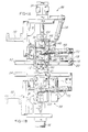
- FIG 1A is an elevational view from the front side of the winding station of apparatus showing parts including the upper run of a stator guide rail and support assembly, a winding nozzle, an upper start wire placing assembly, and parts of a mechanism for retaining the upper winding forms in a stator being wound.
- the wire placing assembly and the stator retaining mechanism are shown in FIG. 1A in the positions they would occupy while a stator is being wound. For simplification, neither the stator being wound nor the winding forms are shown in FIG. 1A.
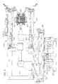
- FIG. 1B is an elevational view similar to FIG. 1A but showing the lower run of the stator guide rail and support assembly and a lower start wire placing assembly and showing the wire placing assembly and the stator retaining mechanism in the positions they would occupy during a time interval between the winding of successively wound stators.
- the apparatus shown in FIG. 1B is located on the sheet of drawing in the same position relative to the apparatus shown in FIG. 1A that it occupies in the assembled apparatus.
- FIG. 2A and 2B are elevation views of the apparatus shown in FIGS. 1A and 1B, respectively, but from the rear side thereof.
- FIG. 3 is a fragmentary, exploded perspective view of a portion of the upper wire placing assembly of FIGS. 1A and 2A.
- FIG. 4 is a perspective view of a wound stator transfer assembly for moving wound stators and stator coil lead wires extending from the coils wound thereon from the winding station, illustrated in block diagram form, to a coil lead terminating station, also illustrated in block diagram form.
- FIG. 5 is a side elevational view, with parts broken away and parts shown in cross section, of the wound stator transfer assembly as viewed in the direction of arrows 5-5 of FIG. 4, and showing a stator guide track and a wound stator in posinon to be transferred along the stator guide track.
- FIG. 6 is a simplified, fragmentary, rear elevational view of the stator track and parts of the wound stator transfer assembly as viewed in the direction of arrows 6-6 of FIG. 5 shown during a time interval in which the wound stator is being transferred from the winding station to the coil lead terminating station.
- FIG. 7 is a side elevational view of a portion of the wound stator transfer assembly as viewed in the direction of arrows 7-7 of FIG. 6 showing the upper finish lead clamp and a fragment of a finish lead which is clamped thereby.
- FIG. 8 is a side elevational view of the portion of the transfer assembly shown in FIG. 7 and showing the upper finish clamp as oriented during a preceding interval of operation of the transfer assembly.
- FIG. 9 is a cross sectional view of a portion of the wound stator transfer assembly taken along line 9-9 of FIG. 6 showing the upper start lead clamp and a fragment of a start lead which is clamped thereby.
- FIG. 9 further diagrammatically shows a wound coil and a start wire portion extending from the wound coil.
- FIG. 10 is a cross sectional view of the wound stator transfer assembly similar to FIG. 9 and showing the upper start lead clamp pivoted to a different position.
- FIG. 11 is a perspective view of an unwound stator located at the winding station with winding forms connected thereto.
- FIG. 11 also includes fragmentary illustrations of the winding shuttle, upper and lower lead pull assemblies, the upper lead placing assemblies, and the stator support track. The parts are shown in FIG. 11 at the commencement of the winding of the stator.
- FIG. 12 is a perspective view similar to FIG. 11 after the commencement of the winding of the stator at the time when the first coil side has been extended through the stator.
- FIG. 13 is a simplified, diagrammatic, cross sectional view illustrating the relative positions of the stator being wound, the winding shuttle, and the lead placing hooks at the time the shuttle nozzle reaches the position thereof shown in FIG. 12.
- FIG. 14 is a perspective view similar to FIGS. 11 and 12 showing the parts during the interval of operation in which the winding ram is rotated to form the first end turn of the first coil and the lead placing hooks are pivoted to pull the coil start wire out of the path of the wire exit points of the shuttle nozzle.
- FIG. 15 is a simplified, diagrammatic, cross sectional view for illustrating the relative positions of the stator being wound, the winding shuttle, and the lead placing hooks at the time shuttle nozzle and lead placing hooks reach the positions thereof shown in FIG. 14.
- FIG. 16 is a simplified, fragmentary, and partly exploded perspective view of a wound stator with coil lead wires extending from the coils wound thereon, a conveyor track for the stator, wire clamps for releasably holding the coil leads, a transfer pin for transferring the stator along the track, and terminal support and wire guide tooling for supporting the stator and the stator terminals and guiding the coil lead wires into the stator terminals.
- the support and wire guide tooling in addition includes a terminal tab crimping and lead wire cutting mechanism by which the lead wires are crimped by the terminal tabs and cut.
- FIG. 16 further shows a portion of a robot end effector that manipulates the lead wires to lay them into the terminal channels and that operates the cutting mechanisms in order to cut the lead wires.
- FIG. 17 is an enlarged, fragmentary perspective view of parts shown in FIG. 16 and illustrates the initial steps of inserting a coil lead wire into the wire-receiving channel of a terminal.
- FIG. 18 a is fragmentary, side elevational view of the stator and terminal support wire guide tooling showing the stator and tooling in positions they occupy in FIG. 17.
- FIG. 19 is a fragmentary, front elevational view of a portion of the terminai support and wire guide tooling, and a cross sectional view of a terminal partly inserted in the tooling as viewed in the direction of and taken along lines 19-19 of FIG. 18.
- FIG. 20 is a fragmentary, front elevational view of another portion of the terminal support and wire guide tooling as viewed in the direction of arrows 20-20 of FIG. 18.
- FIG. 21 is a view similar to FIG. 17 and illustrates further steps resulting in the insertion of a coil lead wire into the wire-receiving channel in the terminal.
- FIG. 22 is a fragmentary, side elevational view of the stator and terminal support and wire guide tooling showing the stator and tooling in positions they occupy in FIG. 21 with a coil lead wire inserted into the terminal channel.
- FIG. 23 is a cross sectional view of a portion of the terminal support and wire guide tooling, the terminal, and the lead wire taken along line 23-23 of FIG. 22.
- FIG. 24 is a view similar to FIGS. 17 and 21 and illustrates the operation of the tab crimping and wire cutting mechanism associated with the terminal support and wire guide tooling.
- FIG. 25 is a fragmentary, side elevational view of the stator and terminal support and wire guide tooling showing the stator and tooling in positions they occupy in FIG. 24 with a coil lead wire crimped by the terminal tabs and a fragment of the wire portion cut away.
- FIG. 26 is a cross sectional view of a portion of the terminal support and wire guide tooling similar to FIG. 23 but taken along line 26-26 of FIG. 25.
- FIG. 27 is a view similar to FIGS. 17,21 and 24 and illustrates the position of parts as a robot end effector moves out of engagement with the terminal tab crimping and lead wire mechanism.
- FIG. 28 is a fragmentary, side elevational view of portions of the crimped terminal and the terminal support and wire guide tooling after completion of the steps shown in FIG. 27.
- FIG. 29 is a fragmentary, rear elevational view of the tooling and terminal as viewed in the direction of arrow 29-29 in FIG. 28.
- FIG. 30 is a fragmentary, exploded perspective view of the terminal support and wire guide tooling including the terminal tab crimping and lead wire cutting mechanism.
- a two-pole stator comprises a pair of field coils 42 and 44 wound on pole pieces of a laminated stator core 46.
- the end face, designated 48, of the stator core 46 which is visible in FIG. 16 is formed from a plastic terminal mounting plate having four terminal-receiving sockets 50 in which are mounted terminals, collectively identified by reference number 52 herein but individually identified in the drawings by numbers 52A, 52B, 52C, and 52D.
- Four coil lead wires, two for each coil 42 and 44, and collectively identified as lead wires 54 in this description are connected to the terminals 52.
- the coil lead wires 54 individually comprise an upper start lead wire 54A, an upper finish lead wire 54B, a lower start lead wire 54C, and a lower finish lead wire 54D,
- FIG. 16 shows the stator 40 supported by upper and lower support or conveyor tracks 58 and 60 at a lead wire terminating station 62 to which it has been moved along the tracks 58 and 60 by a transfer pin 64 adapted to fit within the bore of the stator 40.
- the transfer pin 64 is mounted on a transfer assembly, shown best in FIG. 4, generally designated 66, on which four wire clamps, collectively identified 68, are also mounted.
- the clamps 68 individually comprise an upper start wire clamp 68A, an upper finish wire clamp 68B, a lower start wire clamp 68C, and a lower finish wire clamp 68D.
- the clamps 68 are preferably pneumatically (or electrically) operated so that they may be opened and closed for reasons discussed below.
- the transfer pin 64 is shuttled back and forth between the lead wire terminating station 62 and a stator coil winding station 69.
- a stator 40 located at the winding station 69 is provided, as is conventional, with an upper pair of shrouds or winding forms 70 and a lower pair of shrouds or winding forms 72.
- the winding forms 70 and 72 are effectively clamped to the stator core 46 by upper and lower pairs of form retainer plates 74 and 76 shown in FIGS. 1A, 1B, and 2A, as well known.
- a stator (not shown in these figures) may be advanced by a suitable mechanism (not shown) into the stator coil winding station 69 with its center axis alined with the longitudinal axis of a wire winding ram or shuttle 78.
- Each stator 40 to be wound is supported in the winding station by upper and lower stator guide rails 82 and 84, respectively, that are part of upper and lower winding station tooling assemblies 86 and 88, respectively, which are mounted on fixed frame members 90 and 92.
- the upper and lower winding station tooling assemblies 86 and 88 include retaining blade assembly air actuators 94 and 96, respectively, that drive pistons to which retaining blade mounting blocks 98 and 100, respectively, are affixed.
- the retaining blades 74 and 76 which are constrained to move vertically by guide plates 102, are connected to the blade mounting blocks 98 and 100 by drive pins 104 and 106, respectively.
- the form retaining plates or blades 74 and 76 are moved by operation of the actuators 94 and 96 into three different positions. These comprise a first fully retracted position out of the path of movement of a stator being moved into or out of the winding station 69 and is the position of the lower retaining blades 76 shown in FIG. 1B.
- the second is a fully extended position in which the retaining blades are extended maximally toward the horizontal axis of the stator to engage parts of the winding forms.
- the third position of each of the form retainer blades 74 and 76 is a partially retracted position which is close to the second fully extended position. The retaining blades 74 and 76 are moved to the third position to clamp the winding forms to a stator in preparation for the winding of coils thereon. This is the position of the upper retaining blades 74 shown in FIGS. 1A and 2A.
- a pivotally-mounted stator chuck plate 110 having stator-engaging surfaces 112 and pivotally moved by an air operated clamping actuator 114 that forms part of the upper tooling assembly 86 is used in known fashion to clamp the stator to be wound in an accurately fixed position in the winding station 69.
- the pivot axis of the chuck plate 110 may be fixed, as is conventional, or it may be movable up and down to accommodate stators having different outer dimensions. Thus the pivot axis may be coincident with a pivot pin 116 shown in FIG. 1A that is rotatably received within a bore (not shown) in the chuck plate 110.
- the pivot pin 116 has been cylindrical and its center axis coincident with the axis of the bore within the chuck plate 110, so the chuck plate could only be used to accurately position a stator having one predetermined outer diameter or outer dimension.
- the chuck plate 110 may be adapted for accurately positioning stators having different outer dimensions by providing the pivot pin 116 with an eccentric flange 118 located in the chuck plate bore and by moving the pivot axis of the chuck plate 110 through the range of movements made possible by the eccentricity of the pivot pin flange 118.
- the pivot pin 116 is provided with a knob 120 which may be rotated to change the height of the pivot axis of the chuck plate 110 to accommodate stators of different outer dimensions.
- the presence of a stator in location at the winding station 69 is sensed by a sensing switch that responds to pivotal movement of a sensing plate 121.
- the controls for the apparatus of this invention may comprise conventional machine controls that rely upon various sensing means which, for the most part, are not described herein.
- the stator in the winding station may now be wound by repeated reciprocal and oscillatory movements of the winding shuttle 78 along and about its longitudinal axis to draw wires from sources (not shown) of wire under tension, which wires exit through wire-exit needles 122 and, guided by the winding forms 70 and 72, are wrapped around the stator pole pieces to form the coils 42 and 44 as the shuttle 78 repeatedly reciprocates and oscillates.
- FIG. 11 shows parts in readiness to start the winding of a stator 40.
- the free ends of the wires extending out of the needles 122 are held respectively, by an upper lead pull, hold, and cut assembly 124 and a lower lead pull, hold, and cut assembly 126 which, for simplicity, are called "lead pulls" herein.
- Lead pulls of this type are well known in the art.
- the lead pulls 124 and 126 maintain their grip on the ends of the wires so that the wire segments used to form the stator coils 42 and 44 are drawn through winding shuttle 78.
- the upper start wire placing assembly 140 comprises a pair of elongated, vertically oriented placing blades namely a front placing blade 144 and a rear placing blade 146.
- front is used to refer to the parts of the machinery described herein facing an observer standing in front of the winding shuttle 78; accordingly, the term “rear” is used in the opposite sense.
- the terminals 52 are on the rear side of the stator 40 at the winding station 69.
- the front placing blade 144 is clamped to a pivotally mounted support pin 148, which as shown in FIGS. 1A and 2A is pivotally mounted in the same blade mounting block to which, the retainer plates are connected.
- the rear placing blade 146 has a bore 150 that rotatably receives the pin 148. Clamped to the support pin 148 is a depending drive arm 152 which is held adjacent the rear placing blade 146 by a collar 157 and which has a threaded bore 154 that threadedly receives a drive screw 156.
- Drive screw 156 is threaded to and extends through the bore 154 and its shank is located within a bore 158 in the rear placing blade 146 with which the drive screw 156 is aligned.
- the lower end of the front placing blade 144 is provided with a downwardly and outwardly wire-engaging hook 160.
- the lower end of the rear placing blade 146 is provided with a downwardly facing wire-engaging hook 162.
- an L-shaped drive link 164 is also clamped to the support pin 148 and this link is connected by a bracket 166 to the piston rod of an air operated start wire placing actuator 168 and is pivotally mounted on a support member 170 fixed in relation to the fixed frame member 90.
- FIGS. 11 through 15 illustrate the sequence of operations at the commencement of the winding operations.
- the winding shuttle 78 oscillates from its home position as shown in FIG. 11 as it begins also to reciprocate toward the stator 40.
- the wire engaging blades Prior to this time, the wire engaging blades have been lowered (along with the retaining blades 74 and 76) and pivoted sufficiently toward the center axis of the stator core by operation of the actuator 168 that their wire-engaging hooks 160 and 162 are positioned so that, as the start wire segment 128 is coursed through the bore of the stator. the start wire segment is extended over the rear placing blade hook 162 and adjacent the outwardly facing hook 160 of the front placing blade 144. This condition is illustrated in FIGS. 12 and 13.
- Bore 158 and drive screw 156 provide a lost motion coupling that permits the front placing blade 144 to rotate further than the rear placing blade 146, the difference in the amount of rotation being dependent upon the amount by which the bore 158 is greater in diameter than the shank of the screw 156.
- Such difference may be required as in the case of the stator 40. because of the geometry of the stator and the stator terminals. In the case of the stator 40, a greater rotation of the rear placing blade 146 would place an undue bending moment upon its associated start wire terminal.
- a relatively large rotation of the front placing blade 144 is required to create a relatively large span of the start wire at the front of the stator to avoid too much tension on the wire at the front of the stator. In other cases, there may be no need for a lost motion between the two placing blades and both could be clamped directly to the support pin 148.
- the lower placing assembly 142 is constructed essentially identically to the upper placing assembly 140, except that, for convenience in manufacture, the lower placing actuator, designated 172, operates in a direction opposite to the upper placing actuator 168 and the linkage connecting it to the lower, front placing blade is somewhat different, as is apparent upon a comparison of FIGS. 1A and 1B.
- the start wires 128 and 130 can be held inwardly and outwardly from the stator pole pieces to insure that no portion of the start wires will be wound under succeeding turns of the coils. After the start wires are pulled aside by the placing assemblies 140 and 142, the winding of the stator coils 42 and 44 proceeds to conclusion in conventional fashion.
- the transfer assembly 66 carries the wire clamps to the winding station 69 so that the lead pulls 124 and 126 may be operated to insert the start and finish leads into the wire clamps 68.
- the transfer assembly 66 comprises a fixed base 200 having gibs 202 and a rodless actuator 204 that guide and drive a main transfer carriage 206 in a direction parallel to the conveyor track along which the freshly wound stator 40 is moved to bring it to the lead terminating station 62.
- Main transfer carriage 206 has gibs 210 and a rodless actuator 212 that guide and drive a transfer pin carriage 214 in a direction perpendicular to the conveyor track along which the freshly wound stator 40 is moved to bring it to the lead terminating station 62.
- the transfer pin 64 is mounted on the transfer pin carriage 214. Accordingly, the transfer pin 64 may be shuttled between the coil lead terminating station 62 and the winding station 69 and also moved back and forth, as illustrated in FIG. 5, so that it may move into and out of the bores of successively wound stators to move them along the conveyor tracks 58 and 60 to the coil lead terminating station 62.
- the main transfer carriage 206 also supports a framework 220 on which are mounted upper and lower wire clamp assemblies 222 and 224 respectively, that include the wire clamps 68.
- the main transfer carriage 206 is moved toward the winding station 69 with the pin carriage 214 retracted forwardly away from the winding station 69. This brings the clamps 68 into the winding station.
- the upper finish wire clamp 68B is pivoted by operation of an air actuator 226 carried by the framework 220 to the position shown in FIG. 8 out of the way of the segment of the upper start wire 128 extending between the upper lead pull 124 and the rear placing hook 162.
- start wire clamps 68A and 68C approach the start wires in the winding station 69, they are opened so that their jaws can straddle the start wires.
- the start wire clamps 68A and 68C are thereafter closed to grip the start wires 128 and 130.
- the lead pulls 124 and 126 release them and are moved as needed to hook the finish wires extending from the wound coils to the winding shuttle 78.
- the finish wires may be inserted in conventional fashion between the opened jaws of the finish wire clamps 68B and 68D.
- the upper finish wire clamp 68B is previously pivoted by the actuator 226 to locate it as shown in FIGS. 6 and 7 in position to receive the upper finish lead wire 54.
- the finish wire clamps are now closed to grip the finish wires.
- the winding forms are removed, by known means that forms no part of this invention, and the retaining blades 74 and 76 are retracted by operation of the air actuators 94 and 96. Because the placing blades 144 and 146 are retracted with the retaining blades 74 and 76, the placing blade hooks 160 and 162 become disengaged from the start wire 128 and 130, leaving behind small loops in the start wires 128 and 130 at each end of the stator core 46. The small loops at the front are designated 180 and the small loops at the rear are designated 182. These are removed during subsequent operations as will be described below.
- the parts are now in readiness for the pin carriage 214 to move rearwardly so that the transfer pin 64 is inserted into the freshly wound stator 40.
- the main transfer carriage 206 is returned to the lead terminating station 62, carrying the wound stator and the lead camps 68 with it, as shown in FIG. 6.
- the stator 40 is now located in readiness for the temporary connection of the lead wires 54 to the terminals 52, aligned as shown in FIG. 16.
- each terminal 52 has a longitudinally-extending, wire-receiving channel 250 spaced from its associated socket 50 by a short spacer or channel entry relief section 251.
- the sidewalls 254 of the channel 250 have notches near their outer ends that form tabs 252 at the outer end of each terminal 52 which may be crimped or squeezed together, as shown in FIGS. 25 and 26, to temporarily connect the lead wires to the terminals without changing the shapes of the rest of the terminals 52.
- the remaining portion of the channels 254 are rolled around their respective lead wires at a different processing station (not shown). The notched outer ends of the terminals 52 are cut away at the same station along with any excess lengths of the lead wires.
- the lead wire connecting method and apparatus of this invention utilizes a tooling assembly 260 and an industrial robot.
- the robot is not shown except for its end effector, designated 262.
- the end effector 262 is pliers-like in form and has a first jaw 264 having a bore 266 at its outer end adapted to receive a pin 268 extending from the outer end of a second jaw 270.
- Jaws 264 and 270 are movable horizontally toward and away from each other, as is common in industrial robots, and, for reasons which will become apparent, the gripper jaws 264 and 270 are so controlled that the clamping pressures applied by them can be varied.
- the gripper jaws 264 and 270 may be controlled by a variable air actuator.
- the robot may be entirely conventional and is not further illustrated herein. Although different types of robots may be useful in the practice of this invention, a three-axis Cartesian robot is presently preferred.
- a terminal crimping and wire cutting fixture is affixed to the top of a stanchion 274 which is mounted on a carriage 276 that is driven toward and away from the stator 40 supported in the terminating station 62 by means of a tooling actuator 278.
- the fixture 272 comprises a two-part housing consisting of an H-shaped rear housing plate 280 and a generally cylindrical front body member, generally designated 282.
- the front body member 282 has a first, forwardly projecting, larger diameter arbor section 284 adapted to be snugly received within the bore of the stator 40 at the lead connect terminating station 62, and a seconds smaller diameter arbor section 286 adapted to be received snugly within a bore 288 in the confronting end of the transfer pin 62.
- the front body member 282 also has a pair of vertical slide members 290 and 292 mounted, respectively, on the opposite sides and rear of the large, diameter arbor section 284, which cooperate with the rear housing plate 280 to form chambers within which a pair of spring-biased terminal crimping and lead wire cutting members 294 and 296 are mounted for vertical movement.
- Upper and lower spring retaining plates 298 and 300 are mounted on top and bottom of the rear housing plate 280. They threadedly support alignment pins 302 which confine upper and lower pairs of coil springs 304 that bias the terminal crimping and lead wire cutting members 294 and 296 to a mid position.
- the terminal crimping and lead wire cutting member 294 has an outwardly facing central notch 306 engaged by generally cylindrical upper and lower camming surfaces 308 of a terminal crimping and lead wire cutting actuator lever 310 that is pivotally mounted by a pivot pin (not shown) in socket 312 on the outwardly facing surface of the left side slide member 290 as viewed in FIG. 30.
- the terminal crimping and lead wire cutting member 296 similarly has a notch 306 engaged by another lever 310 pivoted to the other slide member 292.
- the terminal crimping and lead wire cutting member 294 additionally has outwardly facing upper notched portions 314 and lower notched portions 316. Each of the notched portions 314 and 316 cooperate with surfaces on the vertical slide members 290 and 292 to crimp the terminal tabs and sever the excess ends of the lead wires, as will be described below.
- the tooling assembly 272 is driven by the positioning actuator 278 toward the stator 40.
- the arbor sections 284 and 286 advance into engagement with the transfer pin 64 and the bore of the stator 40 to insure that the stator 40 is accurately positioned.
- the terminal 52A rests on an anvil surface on the fixture 272.
- the robot is then activated so that its end effector 262 moves into a location where it can grip the upper start lead wire 54A positioned as shown in full lines in FIG. 17.
- the position of the various lead wires 54 at the lead terminating station 62 can be altered from their positions at the winding station 69-to accommodate the movements of the robot end effector and any tooling constraints.
- the lead wires 54 should be spread further apart at the lead terminating station, and this can be accomplished by appropriately moving the lead wire clamps 58 by means of air actuators such as the actuator 324 shown in FIG. 6.
- the loops in the upper start wire 128 can be partly removed by the simple expedient of rotating the start, wire clamp 68A from the position thereof shown in FIGS. 6 and 9 to its posinon shown in FIG.
- the end effector is manipulated as illustrated in FIGS. 24 through 29 to engage and depress the lever 310 to first cause a hammer portion 330 of the terminal crimping and wire cutting member 294 to crimp the lead wire between the terminal tabs 252 and then sever the lead wire portion remaining connected to the end effector by a shearing action between a cutting blade 332 on the member 294 and a fixed ledge 334 on the vertical slide 290.
- the end effector can be moved as needed to completely remove the loops 180 and 182 in the start wire before the operations shown in FIGS. 17 through 29. Also, it will be readily apparent that, after the first lead wire is severed. the end effector 262 can be opened to discard the remnant piece of wire in its grasp and that the other lead wires can be connected to their respective terminals by similar and appropnate movements of the end effector.
Description
- This invention relates to a stator coil winding method and apparatus particularly intended for the manufacture of two-pole stators for universal electric motors. Although the invention is intended for use in the manufacture of electric motor stators, aspects of the invention may be useful in the manufacture of other electrical devices.
- Two-pole stators for universal electric motors typically have a pair of coils comprising magnet wire having an insulating coating and wound around pole pieces formed on a laminated core. Each coil has two or more wire leads extending therefrom. A practice that has become commonplace in recent years is to mount terminals having wire-receiving channels on the stator cores adjacent the coils to which the coil leads are connected. One such terminal has a longitudinally-extending, U-shaped channel with sidewalls that are notched to form tabs at their outer ends. During manufacture, a coil lead wire is laid into the channel and the tabs crimped together around the lead wire to temporarily clamp the lead wire. At a later stage in the manufacturing process, the channels are rolled around the lead wires to permanently secure the lead wires to the terminals and the tabs are cut away from the remaining parts of the terminals along with any excess lengths of lead wires extending therefrom. When the channels are rolled around the lead wires, a high voltage is applied to the terminals to melt the insulation on the lead wires and burrs or the like on the insides of the channels pierce into the lead wires to create a good electrical connection between the lead wires and the terminals. In preparation for connection of stator coil leads to terminals having U-shaped lead-receiving channels, each of the coil leads is cut during the coil winding process to a length sufficient that it can be held by a wire clamp near the wound stator in a position wherein it extends across the face of the stator adjacent its associated terminal so that it may be mechanically manipulated to be connected to the terminal. In order to achieve connection of a coil lead to a terminal, one practice has been to use a machine generally of the type shown in United States patent No. 3,747,187 having mechanisms to align the coil leads with the channels, to tamp the leads into the channels, and to crimp the sidewalls of the tabs against the lead wires. Such machines typically connect all four lead wires simultaneously. Excess lengths of the lead wire are cut away, usually at a different processing station, by a separate cutter mechanism in preparation for the presentation of the stator to the machine that permanently secures the lead wires to the terminals.
- The wire handling and tab crimping mechanisms of the prior machines are fast-acting and reliable. However, each machine, is dedicated to the manufacture of a stator of but one configuration. If it is desired to use the machine for manufacturing a differently configured stator, the machine usually must be practically completely rebuilt.
- It is also known to use an industrial robot along with appropriate wire guides to lay the lead wires into the terminal channels and to use an auxiliary device to crimp the tabs against the wires. Use of a robot, particularly one that is readily programmable, offers the advantage that a robot can quickly be adapted for use with stators of differing configurations, so that fewer (or no) tooling changes are needed when converting from the manufacture of a stator of one configuration to the manufacture of a stator of a different configuration. However, a simple, programmable industrial robot can only be used to effect connection of one lead wire at a time, and it is necessary to meet high speed production requirements that the robot act with considerable speed.
- Connection of the lead wires to terminals with channels has proved to be difficult to accomplish at a sufficiently high speed with sufficient reliability for mass production. When using a robot to insert lead wires into terminal channels, some means must be provided for guiding the wires into the channels and any corner of a channel around which the lead wire is extended must be protected against engagement by the lead wire. If not protected, the lead wire may snag an the corner and damage the terminal or the insulating coating on the lead wire may be scraped away which would create the potential for an electrical short to occur. Also, the number of movements needed for the end effector of the robot to accomplish its tasks should be kept to a minimum to achieve optimum speed of operation.
- In United States Patent No. 5 090 107 (Application No. 07/511 413) of John M. Beakes and Howard S. Hunter, filed April 20, 1990, titled "Method and Apparatus for Inserting Stator Coil Lead Wires into Terminals having Wire-receiving Channels", a method and apparatus is disclosed wherein a stator locating and terminal support tooling assembly is partly inserted into the bore of a wound stator in order to locate securely the stator at a predetermined. lead wire terminating station. The tooling assembly has an arbor that fits snugly within the bore of the stator to hold it in position and surfaces that prevent engagement between the lead wires and parts of the terminals and surfaces that prevent the terminals from being bent as a result of the steps done to connect the lead wires to the terminals. The end effector of an industrial robot grips a first one of the coil lead wires sufficiently near the coil from which it extends that the stretch of wire between the coil and its gripped portion can be controllably manipulated. (If this stretch of wire is too long, it may be too flexible or rubbery to enable it to be satisfactorily handled during the terminal connection and wire cutting process.) The tooling assembly is partly retracted from the stator so as to expose a relieved portion of the terminal adjacent the end of the channel into which the wire is to be inserted without being so fully retracted that it fails to continue to hold the position of the stator. The tripped wire is laid over the terminal adjacent the end of its wire-receiving channel by movement of the robot end effector while the tooling assembly is partly retracted. The tooling assembly is then fully advanced toward the stator at which time the end of the channel is covered by parts of the tooling assembly. The robot is then manipulated to draw the wire lead into the channel of the terminal. During this time, parts of the terminal subjected to any bending forces are backed up by parts of the tooling assembly. Also, a camming surface provided on the tooling assembly in conjunction with the movement of the robot end effector causes the lead wire to be located deeply within the channel. The foregoing process enables the lead wire to be placed in the terminal channel accurately, reliably, and with minimal end effector motion. The same process is then repeated for placing the other lead wires into the other terminals.
- The method and apparatus of said Patent No. 5 090 107 also includes a method and apparatus for cutting each lead wire and for crimping the terminal tabs to the lead wires. The latter method and apparatus includes cutting blades formed on the tooling assembly. After each lead wire is placed in a terminal channel, it is coursed around and then severed against a cutting blade by movements of the robot end effector. The severed wire segment that remains connected to the end effector is disposed of by separation of the end effector jaws. The end effector jaws are then closed on one another and moved to press one of the terminal tabs against a supporting surface of the tooling assembly.
- The method and apparatus of said Patent No. 5 090 107 has substantial advantages as compared to other methods and apparatus of terminating stator coil lead wires. However, it has a disadvantage in some cases that the end of the lead wire gripped by the robot end effector is cut away before the lead wire is crimped by the terminal tabs. In some cases the cut end of a lead wire between the terminal tabs will, due to its inherent resiliency, move out of the channel area between the tabs so that the subsequent crimping operation will not be effective to hold the lead wire within the terminal.
- A stator locating and terminal support tooling assembly which has an operation similar to the stator locating and terminal support tooling assembly disclosed in Patent No. 5 090 107 may be improved by providing a terminal tab crimping and lead wire cutting mechanism by which the lead wires are each first crimped by the terminal tabs and thus temporarily connected thereto before the ends of the lead wires projecting beyond the terminals are cut away. Accordingly, the positions of the lead wires are maintained at all times by the robot end effector until they are secured to the terminals.
- Further to prevent the winding of the start wires under subsequently wound turns of the coils each start wire placing assembly can include a pair of start wire hooks located at the winding station on opposite sides of a stator to be wound. During the winding of the first coil, the start end of the wires (which are held by lead pull assemblies) are coursed through the stator bore and over the start wire hooks. The start wire hooks are subsequently moved to draw additional wire from the winding shuttle to form small loops in the start wire at each end of the stator core and to thereby hold each start wire away from its associated pole piece. Thus, the entire length of the first coil side being wound can be held out of the path of the nozzle of the winding shuttle and secure from being wound under subsequently wound coils, thereby providing a substantial improvement over prior start wire placing assemblies, such as disclosed in reference to FIGS. 15, 16, and 17 of U.S. patent 4,074,418, granted February 21, 1978, to Harold I. Pearsall, titled "Stator Coil Winding and Lead Wire Cormection", in which only a single hook is provided for holding a start wire away from a pole piece.
- After the winding of the stator coils is completed, the start wire placing assemblies are retracted to thereby remove their start wire hooks from the loops formed in the start wires and a shuttle-type transfer assembly that includes start and finish wire lead clamps is moved into the winding station. The lead pull assemblies, which may be conventional, are manipulated to insert the start and finish leads into the wire lead clamps. The transfer assembly then transfers the wound stator to the lead terminating station for the wire terminating operations described above.
- However, the start wire loops formed by the operation of the start wire placing assemblies would cause the start wires to be excessively long unless steps are taken to pull the loops, and thus the potential for slackness, out of the start wires. The lead-terminating robot may be used for this purpose but it is desirable, in order to maintain adequate control over the handling of the wire by the robot end effector, to minimize the distance by which the robot end effector must move away from the stator while holding a wire.
- Accordingly, the present invention a method of manufacturing stators of the type having a stator core having an end face with terminal receiving sockets and terminals held by said sockets, a pair of coils wound on said stator core, each coil having at least one pair of lead wires extending therefrom, each said lead wire having a fixed end extending from a stator coil and a free end held by a clamp so that it extends alongside its associated said socket one of said lead wires of each of said stator coils being formed so that it is slack, said method comprising the steps of:
- at least partly removing slack in said lead wires by movement of their associated clamps;
- gripping one of said lead wires intermediate its associated said clamp and said coil by a pliers-like robot end effector; and
- moving said end effector to place said lead wire adjacent said terminal for subsequent connection thereto.
-
- Preferably, the step of at least partly removing the slack in said lead wires compnses moving at least one of said clamps between a first position wherein it holds a lead wire at a first distance from said stator core to a second position wherein it holds the lead wire at a second, greater distance from said stator core to thereby reduce slack in the lead wire, each of said terminals having a trough-like, longitudinally-extending, wire-receiving channel, and said method further comprises the step of moving said end effector to place said one of said lead wires into said channel.
- Also provided in accordance with the invention is an apparatus for manufacturing stators having coils each having at least one pair of lead wires extending therefrom, one of the lead wires of each of said stator coils being formed so that it is slack, said apparatus comprising:
- plural wire clamps for temporarily holding each of said lead wires;
- means for positioning said stator core and said wire clamps at a lead termination station; and
- a plier-like robot end effector for successively griping each of said lead wires and removing it from its associated clamp for connection to a terminal member; characterised in that each of the wire clamps which temporarily holds the slack lead wire of each coil is movable relative to said stator to at lease partly remove the slack from the associated slack lead wire.
-
- In the preffered embodiment of each of said wire clamps that temporarily holds the slack lead wire of each coil is pivotally mounted relative to said stator.
- By mounting the wire clamps for pivotal movement in direction which will enable them to at least partly pull out the start wire loops before the robot grips the start wires. The robot end effector can be used to remove any additional excess start wire lengths not removed as a result of the pivotal movements of the wire clamps.
- It will be recognized that the start wire placing method and apparatus of this invention may be used with different lead terminating methods- and apparatus. However, these two aspects of the application are highly compatible in view of the need to accommodate or remove the excess lengths of the start wires as described above.
- Other features and advantages will become apparent from the following description and the drawings.
- FIG 1A is an elevational view from the front side of the winding station of apparatus showing parts including the upper run of a stator guide rail and support assembly, a winding nozzle, an upper start wire placing assembly, and parts of a mechanism for retaining the upper winding forms in a stator being wound. The wire placing assembly and the stator retaining mechanism are shown in FIG. 1A in the positions they would occupy while a stator is being wound. For simplification, neither the stator being wound nor the winding forms are shown in FIG. 1A.
- FIG. 1B is an elevational view similar to FIG. 1A but showing the lower run of the stator guide rail and support assembly and a lower start wire placing assembly and showing the wire placing assembly and the stator retaining mechanism in the positions they would occupy during a time interval between the winding of successively wound stators. The apparatus shown in FIG. 1B is located on the sheet of drawing in the same position relative to the apparatus shown in FIG. 1A that it occupies in the assembled apparatus.
- FIG. 2A and 2B are elevation views of the apparatus shown in FIGS. 1A and 1B, respectively, but from the rear side thereof.
- FIG. 3 is a fragmentary, exploded perspective view of a portion of the upper wire placing assembly of FIGS. 1A and 2A.
- FIG. 4 is a perspective view of a wound stator transfer assembly for moving wound stators and stator coil lead wires extending from the coils wound thereon from the winding station, illustrated in block diagram form, to a coil lead terminating station, also illustrated in block diagram form.
- FIG. 5 is a side elevational view, with parts broken away and parts shown in cross section, of the wound stator transfer assembly as viewed in the direction of arrows 5-5 of FIG. 4, and showing a stator guide track and a wound stator in posinon to be transferred along the stator guide track.
- FIG. 6 is a simplified, fragmentary, rear elevational view of the stator track and parts of the wound stator transfer assembly as viewed in the direction of arrows 6-6 of FIG. 5 shown during a time interval in which the wound stator is being transferred from the winding station to the coil lead terminating station.
- FIG. 7 is a side elevational view of a portion of the wound stator transfer assembly as viewed in the direction of arrows 7-7 of FIG. 6 showing the upper finish lead clamp and a fragment of a finish lead which is clamped thereby.
- FIG. 8 is a side elevational view of the portion of the transfer assembly shown in FIG. 7 and showing the upper finish clamp as oriented during a preceding interval of operation of the transfer assembly.
- FIG. 9 is a cross sectional view of a portion of the wound stator transfer assembly taken along line 9-9 of FIG. 6 showing the upper start lead clamp and a fragment of a start lead which is clamped thereby. FIG. 9 further diagrammatically shows a wound coil and a start wire portion extending from the wound coil.
- FIG. 10 is a cross sectional view of the wound stator transfer assembly similar to FIG. 9 and showing the upper start lead clamp pivoted to a different position.
- FIG. 11 is a perspective view of an unwound stator located at the winding station with winding forms connected thereto. FIG. 11 also includes fragmentary illustrations of the winding shuttle, upper and lower lead pull assemblies, the upper lead placing assemblies, and the stator support track. The parts are shown in FIG. 11 at the commencement of the winding of the stator.
- FIG. 12 is a perspective view similar to FIG. 11 after the commencement of the winding of the stator at the time when the first coil side has been extended through the stator.
- FIG. 13 is a simplified, diagrammatic, cross sectional view illustrating the relative positions of the stator being wound, the winding shuttle, and the lead placing hooks at the time the shuttle nozzle reaches the position thereof shown in FIG. 12.
- FIG. 14 is a perspective view similar to FIGS. 11 and 12 showing the parts during the interval of operation in which the winding ram is rotated to form the first end turn of the first coil and the lead placing hooks are pivoted to pull the coil start wire out of the path of the wire exit points of the shuttle nozzle.
- FIG. 15 is a simplified, diagrammatic, cross sectional view for illustrating the relative positions of the stator being wound, the winding shuttle, and the lead placing hooks at the time shuttle nozzle and lead placing hooks reach the positions thereof shown in FIG. 14.
- FIG. 16 is a simplified, fragmentary, and partly exploded perspective view of a wound stator with coil lead wires extending from the coils wound thereon, a conveyor track for the stator, wire clamps for releasably holding the coil leads, a transfer pin for transferring the stator along the track, and terminal support and wire guide tooling for supporting the stator and the stator terminals and guiding the coil lead wires into the stator terminals. The support and wire guide tooling in addition includes a terminal tab crimping and lead wire cutting mechanism by which the lead wires are crimped by the terminal tabs and cut. FIG. 16 further shows a portion of a robot end effector that manipulates the lead wires to lay them into the terminal channels and that operates the cutting mechanisms in order to cut the lead wires.
- FIG. 17 is an enlarged, fragmentary perspective view of parts shown in FIG. 16 and illustrates the initial steps of inserting a coil lead wire into the wire-receiving channel of a terminal.
- FIG. 18 a is fragmentary, side elevational view of the stator and terminal support wire guide tooling showing the stator and tooling in positions they occupy in FIG. 17.
- FIG. 19 is a fragmentary, front elevational view of a portion of the terminai support and wire guide tooling, and a cross sectional view of a terminal partly inserted in the tooling as viewed in the direction of and taken along lines 19-19 of FIG. 18.
- FIG. 20 is a fragmentary, front elevational view of another portion of the terminal support and wire guide tooling as viewed in the direction of arrows 20-20 of FIG. 18.
- FIG. 21 is a view similar to FIG. 17 and illustrates further steps resulting in the insertion of a coil lead wire into the wire-receiving channel in the terminal.
- FIG. 22 is a fragmentary, side elevational view of the stator and terminal support and wire guide tooling showing the stator and tooling in positions they occupy in FIG. 21 with a coil lead wire inserted into the terminal channel.
- FIG. 23 is a cross sectional view of a portion of the terminal support and wire guide tooling, the terminal, and the lead wire taken along line 23-23 of FIG. 22.
- FIG. 24 is a view similar to FIGS. 17 and 21 and illustrates the operation of the tab crimping and wire cutting mechanism associated with the terminal support and wire guide tooling.
- FIG. 25 is a fragmentary, side elevational view of the stator and terminal support and wire guide tooling showing the stator and tooling in positions they occupy in FIG. 24 with a coil lead wire crimped by the terminal tabs and a fragment of the wire portion cut away.
- FIG. 26 is a cross sectional view of a portion of the terminal support and wire guide tooling similar to FIG. 23 but taken along line 26-26 of FIG. 25.
- FIG. 27 is a view similar to FIGS. 17,21 and 24 and illustrates the position of parts as a robot end effector moves out of engagement with the terminal tab crimping and lead wire mechanism.
- FIG. 28 is a fragmentary, side elevational view of portions of the crimped terminal and the terminal support and wire guide tooling after completion of the steps shown in FIG. 27.
- FIG. 29 is a fragmentary, rear elevational view of the tooling and terminal as viewed in the direction of arrow 29-29 in FIG. 28.
- FIG. 30 is a fragmentary, exploded perspective view of the terminal support and wire guide tooling including the terminal tab crimping and lead wire cutting mechanism.
- With reference to FIG. 16, a two-pole stator, generally designated 40, comprises a pair of field coils 42 and 44 wound on pole pieces of a
laminated stator core 46. The end face, designated 48, of thestator core 46 which is visible in FIG. 16 is formed from a plastic terminal mounting plate having four terminal-receivingsockets 50 in which are mounted terminals, collectively identified byreference number 52 herein but individually identified in the drawings bynumbers coil lead wires 54 in this description are connected to theterminals 52. Thecoil lead wires 54 individually comprise an upperstart lead wire 54A, an upper finish lead wire 54B, a lowerstart lead wire 54C, and a lower finish lead wire 54D, - FIG. 16 shows the
stator 40 supported by upper and lower support or conveyor tracks 58 and 60 at a leadwire terminating station 62 to which it has been moved along thetracks transfer pin 64 adapted to fit within the bore of thestator 40. In accordance with known practice, thetransfer pin 64 is mounted on a transfer assembly, shown best in FIG. 4, generally designated 66, on which four wire clamps, collectively identified 68, are also mounted. With reference also to FIG. 6, theclamps 68 individually comprise an upperstart wire clamp 68A, an upperfinish wire clamp 68B, a lowerstart wire clamp 68C, and a lowerfinish wire clamp 68D. Theclamps 68 are preferably pneumatically (or electrically) operated so that they may be opened and closed for reasons discussed below. - As illustrated diagrammatically in FIG. 4, the
transfer pin 64 is shuttled back and forth between the leadwire terminating station 62 and a statorcoil winding station 69. With reference to FIGS. 11-15, astator 40 located at the windingstation 69 is provided, as is conventional, with an upper pair of shrouds or windingforms 70 and a lower pair of shrouds or windingforms 72. The winding forms 70 and 72 are effectively clamped to thestator core 46 by upper and lower pairs ofform retainer plates - With reference to FIGS. 1A, 1B, 2A and 2B, a stator (not shown in these figures) may be advanced by a suitable mechanism (not shown) into the stator
coil winding station 69 with its center axis alined with the longitudinal axis of a wire winding ram orshuttle 78. Eachstator 40 to be wound is supported in the winding station by upper and lowerstator guide rails station tooling assemblies frame members station tooling assemblies assembly air actuators blade mounting blocks blades blade mounting blocks drive pins blades actuators station 69 and is the position of thelower retaining blades 76 shown in FIG. 1B. The second is a fully extended position in which the retaining blades are extended maximally toward the horizontal axis of the stator to engage parts of the winding forms. The third position of each of theform retainer blades blades upper retaining blades 74 shown in FIGS. 1A and 2A. - A pivotally-mounted
stator chuck plate 110 having stator-engagingsurfaces 112 and pivotally moved by an air operated clampingactuator 114 that forms part of theupper tooling assembly 86 is used in known fashion to clamp the stator to be wound in an accurately fixed position in the windingstation 69. The pivot axis of thechuck plate 110 may be fixed, as is conventional, or it may be movable up and down to accommodate stators having different outer dimensions. Thus the pivot axis may be coincident with apivot pin 116 shown in FIG. 1A that is rotatably received within a bore (not shown) in thechuck plate 110. In the past, thepivot pin 116 has been cylindrical and its center axis coincident with the axis of the bore within thechuck plate 110, so the chuck plate could only be used to accurately position a stator having one predetermined outer diameter or outer dimension. Thechuck plate 110 may be adapted for accurately positioning stators having different outer dimensions by providing thepivot pin 116 with aneccentric flange 118 located in the chuck plate bore and by moving the pivot axis of thechuck plate 110 through the range of movements made possible by the eccentricity of thepivot pin flange 118. In FIG. 1A it will be noted that thepivot pin 116 is provided with aknob 120 which may be rotated to change the height of the pivot axis of thechuck plate 110 to accommodate stators of different outer dimensions. - With reference to FIG. 2B, the presence of a stator in location at the winding
station 69 is sensed by a sensing switch that responds to pivotal movement of a sensing plate 121. (Here it may be noted that the controls for the apparatus of this invention may comprise conventional machine controls that rely upon various sensing means which, for the most part, are not described herein.) The stator in the winding station may now be wound by repeated reciprocal and oscillatory movements of the windingshuttle 78 along and about its longitudinal axis to draw wires from sources (not shown) of wire under tension, which wires exit through wire-exit needles 122 and, guided by the windingforms coils shuttle 78 repeatedly reciprocates and oscillates. - FIG. 11 shows parts in readiness to start the winding of a
stator 40. At this time, the free ends of the wires extending out of theneedles 122 are held respectively, by an upper lead pull, hold, and cutassembly 124 and a lower lead pull, hold, and cutassembly 126 which, for simplicity, are called "lead pulls" herein. Lead pulls of this type are well known in the art. During the winding operation, the lead pulls 124 and 126 maintain their grip on the ends of the wires so that the wire segments used to form the stator coils 42 and 44 are drawn through windingshuttle 78. - The start wires, designated 128 and 130, which are the wire segments leading from the lead pulls 124 and 126 and extending through the bore of the stator to form the first sides of the first coils wound, are held away from the stator pole pieces by respective upper and lower start wire placing assemblies, generally designated 140 and 142. Referring to FIGS. 3 and 11, the upper start
wire placing assembly 140 comprises a pair of elongated, vertically oriented placing blades namely afront placing blade 144 and arear placing blade 146. (For convenience, the term "front" is used to refer to the parts of the machinery described herein facing an observer standing in front of the windingshuttle 78; accordingly, the term "rear" is used in the opposite sense. Thus for example, theterminals 52 are on the rear side of thestator 40 at the windingstation 69.) Thefront placing blade 144 is clamped to a pivotally mountedsupport pin 148, which as shown in FIGS. 1A and 2A is pivotally mounted in the same blade mounting block to which, the retainer plates are connected. Therear placing blade 146 has abore 150 that rotatably receives thepin 148. Clamped to thesupport pin 148 is a dependingdrive arm 152 which is held adjacent therear placing blade 146 by a collar 157 and which has a threadedbore 154 that threadedly receives adrive screw 156.Drive screw 156 is threaded to and extends through thebore 154 and its shank is located within abore 158 in therear placing blade 146 with which thedrive screw 156 is aligned. The lower end of thefront placing blade 144 is provided with a downwardly and outwardly wire-engaginghook 160. The lower end of therear placing blade 146 is provided with a downwardly facing wire-engaginghook 162. Referring to FIG. 1A, an L-shapeddrive link 164 is also clamped to thesupport pin 148 and this link is connected by a bracket 166 to the piston rod of an air operated startwire placing actuator 168 and is pivotally mounted on asupport member 170 fixed in relation to the fixedframe member 90. - FIGS. 11 through 15 illustrate the sequence of operations at the commencement of the winding operations. The winding
shuttle 78 oscillates from its home position as shown in FIG. 11 as it begins also to reciprocate toward thestator 40. Prior to this time, the wire engaging blades have been lowered (along with the retainingblades 74 and 76) and pivoted sufficiently toward the center axis of the stator core by operation of theactuator 168 that their wire-engaginghooks start wire segment 128 is coursed through the bore of the stator. the start wire segment is extended over the rearplacing blade hook 162 and adjacent the outwardly facinghook 160 of thefront placing blade 144. This condition is illustrated in FIGS. 12 and 13. - With reference to FIGS. 14 and 15, as the
shuttle 78 undergoes an oscillation to form the first end turn at the front end of thestator 40, its movement is momentarily interrupted and the placingactuator 168 is energized to rotate thesupport pin 148 so as to drive thefront placing blade 144 away from the center of thestator 40. Rotation of thesupport pin 148 also causes rotation of the dependingdrive arm 152 which in turn imparts a rotary motion to therear placing blade 146 due to the engagement of the margins of thebore 158 by thedrive screw 156.Bore 158 and drivescrew 156 provide a lost motion coupling that permits thefront placing blade 144 to rotate further than therear placing blade 146, the difference in the amount of rotation being dependent upon the amount by which thebore 158 is greater in diameter than the shank of thescrew 156. Such difference may be required as in the case of thestator 40. because of the geometry of the stator and the stator terminals. In the case of thestator 40, a greater rotation of therear placing blade 146 would place an undue bending moment upon its associated start wire terminal. A relatively large rotation of thefront placing blade 144 is required to create a relatively large span of the start wire at the front of the stator to avoid too much tension on the wire at the front of the stator. In other cases, there may be no need for a lost motion between the two placing blades and both could be clamped directly to thesupport pin 148. - With reference to FIG. 1B, the
lower placing assembly 142 is constructed essentially identically to theupper placing assembly 140, except that, for convenience in manufacture, the lower placing actuator, designated 172, operates in a direction opposite to theupper placing actuator 168 and the linkage connecting it to the lower, front placing blade is somewhat different, as is apparent upon a comparison of FIGS. 1A and 1B. - Because of the Provision of the placing blades, the
start wires assemblies - After the winding of the stator coils 42 and 44 is completed, the
transfer assembly 66 carries the wire clamps to the windingstation 69 so that the lead pulls 124 and 126 may be operated to insert the start and finish leads into the wire clamps 68. With reference to FIG. 4, thetransfer assembly 66 comprises a fixedbase 200 havinggibs 202 and arodless actuator 204 that guide and drive amain transfer carriage 206 in a direction parallel to the conveyor track along which the freshly woundstator 40 is moved to bring it to thelead terminating station 62.Main transfer carriage 206 has gibs 210 and arodless actuator 212 that guide and drive atransfer pin carriage 214 in a direction perpendicular to the conveyor track along which the freshly woundstator 40 is moved to bring it to thelead terminating station 62. Thetransfer pin 64 is mounted on thetransfer pin carriage 214. Accordingly, thetransfer pin 64 may be shuttled between the coillead terminating station 62 and the windingstation 69 and also moved back and forth, as illustrated in FIG. 5, so that it may move into and out of the bores of successively wound stators to move them along the conveyor tracks 58 and 60 to the coillead terminating station 62. - The
main transfer carriage 206 also supports aframework 220 on which are mounted upper and lowerwire clamp assemblies coils main transfer carriage 206 is moved toward the windingstation 69 with thepin carriage 214 retracted forwardly away from the windingstation 69. This brings theclamps 68 into the winding station. At this time, the upperfinish wire clamp 68B is pivoted by operation of anair actuator 226 carried by theframework 220 to the position shown in FIG. 8 out of the way of the segment of theupper start wire 128 extending between the upper lead pull 124 and therear placing hook 162. As the start wire clamps 68A and 68C approach the start wires in the windingstation 69, they are opened so that their jaws can straddle the start wires. The start wire clamps 68A and 68C are thereafter closed to grip thestart wires - After the
start wires clamps shuttle 78. Once the finish wires have been hooked, they may be inserted in conventional fashion between the opened jaws of the finish wire clamps 68B and 68D. Of course, the upperfinish wire clamp 68B is previously pivoted by theactuator 226 to locate it as shown in FIGS. 6 and 7 in position to receive the upperfinish lead wire 54. The finish wire clamps are now closed to grip the finish wires. - After the wire leads 54 are connected to the
clamps 68, as just described, the winding forms are removed, by known means that forms no part of this invention, and theretaining blades air actuators placing blades blades start wire start wires stator core 46. The small loops at the front are designated 180 and the small loops at the rear are designated 182. These are removed during subsequent operations as will be described below. The parts are now in readiness for thepin carriage 214 to move rearwardly so that thetransfer pin 64 is inserted into the freshly woundstator 40. When this is accomplished, themain transfer carriage 206 is returned to thelead terminating station 62, carrying the wound stator and thelead camps 68 with it, as shown in FIG. 6. Thestator 40 is now located in readiness for the temporary connection of thelead wires 54 to theterminals 52, aligned as shown in FIG. 16. - Before describing the lead terminating apparatus and method, it may be helpful to note that the illustrated
terminals 52 are of a type commercially available from AMP Incorporated of Harrisburg, Pennsylvania. Each terminal 52 has a longitudinally-extending, wire-receiving channel 250 spaced from its associatedsocket 50 by a short spacer or channelentry relief section 251. Thesidewalls 254 of the channel 250 have notches near their outer ends that formtabs 252 at the outer end of each terminal 52 which may be crimped or squeezed together, as shown in FIGS. 25 and 26, to temporarily connect the lead wires to the terminals without changing the shapes of the rest of theterminals 52. As previously mentioned, the remaining portion of thechannels 254 are rolled around their respective lead wires at a different processing station (not shown). The notched outer ends of theterminals 52 are cut away at the same station along with any excess lengths of the lead wires. - The lead wire connecting method and apparatus of this invention utilizes a
tooling assembly 260 and an industrial robot. The robot is not shown except for its end effector, designated 262. As best shown in FIG. 16, theend effector 262 is pliers-like in form and has afirst jaw 264 having abore 266 at its outer end adapted to receive apin 268 extending from the outer end of asecond jaw 270.Jaws gripper jaws gripper jaws - With reference to FIGS. 16 and 30, a terminal crimping and wire cutting fixture, generally designated 272, is affixed to the top of a
stanchion 274 which is mounted on acarriage 276 that is driven toward and away from thestator 40 supported in the terminatingstation 62 by means of atooling actuator 278. - The
fixture 272 comprises a two-part housing consisting of an H-shapedrear housing plate 280 and a generally cylindrical front body member, generally designated 282. Thefront body member 282 has a first, forwardly projecting, largerdiameter arbor section 284 adapted to be snugly received within the bore of thestator 40 at the lead connect terminatingstation 62, and a seconds smallerdiameter arbor section 286 adapted to be received snugly within abore 288 in the confronting end of thetransfer pin 62. Thefront body member 282 also has a pair ofvertical slide members diameter arbor section 284, which cooperate with therear housing plate 280 to form chambers within which a pair of spring-biased terminal crimping and leadwire cutting members spring retaining plates rear housing plate 280. They threadedly support alignment pins 302 which confine upper and lower pairs ofcoil springs 304 that bias the terminal crimping and leadwire cutting members - The terminal crimping and lead
wire cutting member 294 has an outwardly facingcentral notch 306 engaged by generally cylindrical upper and lower camming surfaces 308 of a terminal crimping and lead wire cuttingactuator lever 310 that is pivotally mounted by a pivot pin (not shown) insocket 312 on the outwardly facing surface of the leftside slide member 290 as viewed in FIG. 30.The terminal crimping and leadwire cutting member 296 similarly has anotch 306 engaged by anotherlever 310 pivoted to theother slide member 292. - The terminal crimping and lead
wire cutting member 294 additionally has outwardly facing upper notchedportions 314 and lower notchedportions 316. Each of the notchedportions vertical slide members - In operation, with reference to FIGS. 16-29, when a
stator 40 reaches thelead termination station 62, thetooling assembly 272 is driven by thepositioning actuator 278 toward thestator 40. Thearbor sections transfer pin 64 and the bore of thestator 40 to insure that thestator 40 is accurately positioned. At this time, as shown in FIG. 18, theterminal 52A rests on an anvil surface on thefixture 272. The robot is then activated so that itsend effector 262 moves into a location where it can grip the upperstart lead wire 54A positioned as shown in full lines in FIG. 17. - Here, it should be noted that the position of the various
lead wires 54 at thelead terminating station 62 can be altered from their positions at the winding station 69-to accommodate the movements of the robot end effector and any tooling constraints. In general, it is found that thelead wires 54 should be spread further apart at the lead terminating station, and this can be accomplished by appropriately moving the lead wire clamps 58 by means of air actuators such as theactuator 324 shown in FIG. 6. Also, it should be noted that the loops in theupper start wire 128 can be partly removed by the simple expedient of rotating the start,wire clamp 68A from the position thereof shown in FIGS. 6 and 9 to its posinon shown in FIG. 10 by means ofair actuator 226, whereupon theupper start wire 128 is pulled upwardly and outwardly away from the stator core. Thelower start wire 130 can be handled identically using air actuator 228 to pivot the lowerstart wire clamp 68C. As diagrammatically represented in FIG. 10, such movement of the start wire clamps may be sufficient to at least completely remove one of theloops 180. Such movements of the start wire clamps must, of course, be accomplished prior to the operation of the robot end effector. Otherwise, there would be too much slack wire for the end effector to handle properly. - Returning to the operation of the
end effector 262 and the crimping and cuttingfixture 272, the end effector operations to lay the wire into the terminal channel is evident from an inspection of FIGS. 17 thorough 23. It should be noted in Figures 18 through 20 that thefixture 272 is held slightly spaced from thestator 40 when theend effector 262 is manipulated to lay the wire overterminal socket 50. This is a step that would not be needed with a socket or a terminal of a different configuration. - After the wire is inserted into the channel, the end effector is manipulated as illustrated in FIGS. 24 through 29 to engage and depress the
lever 310 to first cause ahammer portion 330 of the terminal crimping andwire cutting member 294 to crimp the lead wire between theterminal tabs 252 and then sever the lead wire portion remaining connected to the end effector by a shearing action between acutting blade 332 on themember 294 and a fixedledge 334 on thevertical slide 290. - It will be recognized that the end effector can be moved as needed to completely remove the
loops end effector 262 can be opened to discard the remnant piece of wire in its grasp and that the other lead wires can be connected to their respective terminals by similar and appropnate movements of the end effector. - Although the presently preferred embodiment of this invention has been descnbed, it will be understood that within the purview of this invention various changes may be made within the scope of the following claims.
Claims (4)
- A method of manufacturing stators (40) of the type having a stator core (46) having an end face (48) with terminal receiving sockets (50) and terminals (52) held by said sockets (50), a pair of coils (42,44) wound on said stator core (46), each coil (42,44) having at least one pair of lead wires (54) extending therefrom, each said lead wire (54) having a fixed end extending from a stator coil (42,44) and a free end held by a clamp (68) so that it extends alongside its associated said socket (50), one of said lead wires (54) of each of said stator coils (42,44) being formed so that it is slack, said method comprising the steps of:at least partly removing slack in said lead wires (54) by movement of their associated clamps (68);gripping one of said lead wires (54) intermediate its associated said clamp (68) and said coil (42,44) by a pliers-like robot end effector (262); andmoving said end effector (262) to place said lead wire (54) adjacent said terminal (52) for subsequent connection thereto.
- A method according to claim 1 wherein the step of at least partly removing the slack in said lead wires (54) comprises moving at least one of said clamps (68) between a first position wherein it holds a lead wire (54) at a first distance from said stator core (46) to a second position wherein it holds the lead wire (54) at a second, greater distance from said stator core (46) to thereby reduce slack in the lead wire (54), each of said terminals (52) having a trough-like, longitudinally-extending, wire-receiving channel (250), and said method further comprises the step of moving said end effector (262) to place said one of said lead wires (54) into said channel (250).
- An apparatus for manufacturing stators (40) having coils (42,44) each having at least one pair of lead wires (54) extending therefrom, one of the lead wires (54) of each of said stator coils (42,44) being formed so that it is slack, said apparatus comprising:characterised in that each of the wire clamps (68) which temporarily holds the slack lead wire (54) of each coil (42,44) is movable relative to said stator (40) to at lease partly remove the slack from the associated slack lead wire (54).plural wire clamps (68) for temporarily holding each of said lead wires (54);means for positioning said stator core (46) and said wire clamps (68) at a lead termination station (62); anda plier-like robot end effector (262) for successively griping each of said lead wires (54) and removing it from its associated clamp (68) for connection to a terminal member (52);
- The apparatus of claim 3 wherein each of said wire clamps (68) that temporarily holds the slack lead wire (54) of each coil (42,44) is pivotally mounted relative to said stator (40).
Applications Claiming Priority (3)
| Application Number | Priority Date | Filing Date | Title |
|---|---|---|---|
| US07/598,878 US5090108A (en) | 1990-10-17 | 1990-10-17 | Stator coil winding and lead termination method and apparatus |
| US598878 | 1990-10-17 | ||
| EP91309553A EP0481769B1 (en) | 1990-10-17 | 1991-10-17 | Stator coil winding and lead termination method and apparatus |
Related Parent Applications (2)
| Application Number | Title | Priority Date | Filing Date |
|---|---|---|---|
| EP91309553.5 Division | 1991-10-17 | ||
| EP91309553A Division EP0481769B1 (en) | 1990-10-17 | 1991-10-17 | Stator coil winding and lead termination method and apparatus |
Publications (2)
| Publication Number | Publication Date |
|---|---|
| EP0763879A1 EP0763879A1 (en) | 1997-03-19 |
| EP0763879B1 true EP0763879B1 (en) | 1999-03-31 |
Family
ID=24397293
Family Applications (2)
| Application Number | Title | Priority Date | Filing Date |
|---|---|---|---|
| EP91309553A Expired - Lifetime EP0481769B1 (en) | 1990-10-17 | 1991-10-17 | Stator coil winding and lead termination method and apparatus |
| EP96203021A Expired - Lifetime EP0763879B1 (en) | 1990-10-17 | 1991-10-17 | Stator coil winding method and apparatus |
Family Applications Before (1)
| Application Number | Title | Priority Date | Filing Date |
|---|---|---|---|
| EP91309553A Expired - Lifetime EP0481769B1 (en) | 1990-10-17 | 1991-10-17 | Stator coil winding and lead termination method and apparatus |
Country Status (4)
| Country | Link |
|---|---|
| US (1) | US5090108A (en) |
| EP (2) | EP0481769B1 (en) |
| JP (1) | JPH04289753A (en) |
| DE (2) | DE69131080T2 (en) |
Families Citing this family (31)
| Publication number | Priority date | Publication date | Assignee | Title |
|---|---|---|---|---|
| US5065503A (en) * | 1990-08-01 | 1991-11-19 | Axis, U.S.A., Inc. | Apparatus for connecting stator coil leads |
| US5340043A (en) * | 1992-06-16 | 1994-08-23 | Globe Products Inc. | Stator winding apparatus including winding form assemblies |
| EP0700575B1 (en) * | 1993-05-28 | 1997-01-02 | Amatech Gmbh & Co. KG | Winding head |
| US5535503A (en) * | 1993-12-03 | 1996-07-16 | Globe Products Inc. | Stator lead wire connection method and apparatus |
| US5653014A (en) * | 1994-09-13 | 1997-08-05 | Axis Usa, Inc. | Dynamo-electric machine component conveying systems and load/unload devices |
| US5680696A (en) * | 1994-09-13 | 1997-10-28 | Axis Usa, Inc. | Dynamo-electric machine component conveying systems with load/unload devices |
| US5685061A (en) * | 1995-04-20 | 1997-11-11 | Globe Products Inc. | Stator manufacturing method |
| US5586384A (en) * | 1995-04-28 | 1996-12-24 | Globe Products Inc. | Stator manufacturing method and apparatus |
| US5755021A (en) * | 1995-07-07 | 1998-05-26 | Globe Products Inc. | Stator lead wire connecting method |
| US5855058A (en) * | 1996-04-18 | 1999-01-05 | Globe Products Inc. | Armature manufacturing apparatus |
| US5765274A (en) * | 1996-05-21 | 1998-06-16 | Globe Products Inc. | Stator manufacturing method |
| WO1998001934A1 (en) * | 1996-07-09 | 1998-01-15 | Globe Products Inc. | Stator lead wire connecting method and apparatus |
| US5833166A (en) * | 1996-07-25 | 1998-11-10 | Globe Products Inc. | Stator coil winding and lead wire placing method and apparatus |
| EP1012947A2 (en) * | 1996-10-28 | 2000-06-28 | Globe Products Inc. | Stator coil lead termination method and apparatus |
| WO1998039835A1 (en) * | 1997-02-24 | 1998-09-11 | Globe Products Inc. | Stator manufacturing method and apparatus |
| US5895004A (en) * | 1997-04-07 | 1999-04-20 | Labinal Components & Systems, Inc. | Coil winding apparatus for large diameter magnetic rings |
| US6519832B1 (en) * | 1998-07-27 | 2003-02-18 | Reliance Electric Technologies, Llc | Method for automated stator manufacture |
| WO2000046903A1 (en) * | 1999-02-03 | 2000-08-10 | Globe Products Inc. | Stator coil winding with start wire protection |
| US6533209B2 (en) * | 1999-12-23 | 2003-03-18 | Axis Usa, Inc. | Dynamo-electric machine stator winder methods and apparatus with loop-forming wire pullers |
| JP3811892B2 (en) * | 2002-06-28 | 2006-08-23 | ミネベア株式会社 | Sag formation mechanism of stator winding |
| CN101079564B (en) * | 2002-10-04 | 2010-06-02 | 松下电器产业株式会社 | Method of winding stator for motor |
| US7877863B2 (en) * | 2005-06-27 | 2011-02-01 | Remy Technologies, L.L.C. | Apparatus for routing conductors in electro-mechanical machine housings |
| CN2875135Y (en) * | 2005-10-17 | 2007-03-07 | 超源实业有限公司 | Broad width neck suspender |
| CN102545413B (en) * | 2006-11-20 | 2014-07-09 | 阿斯莫株式会社 | Armature and motor |
| TR201103641A2 (en) * | 2011-04-14 | 2012-11-21 | General Electric Company | Electrical machine component mounting bracket |
| DK2750660T3 (en) | 2011-08-29 | 2016-12-12 | Mati Therapeutics Inc | FILING WITH PROLONGED RELEASE OF ACTIVE AGENTS to treat glaucoma and ocular hypertension |
| WO2013126419A1 (en) * | 2012-02-20 | 2013-08-29 | Louis Finkle | Apparatus and method for efficient stator windings termination |
| DE102012208127A1 (en) * | 2012-05-15 | 2013-11-21 | Metabowerke Gmbh | Method for producing a stator of an electric drive |
| JP5931228B1 (en) | 2015-01-06 | 2016-06-08 | ファナック株式会社 | Armature with windings and method for connecting armature winding terminals to terminals |
| US10523075B2 (en) * | 2016-11-16 | 2019-12-31 | Tesla, Inc. | Automatic stator wire lead routing |
| CN116455159B (en) * | 2023-06-14 | 2023-09-15 | 广东敏卓机电股份有限公司 | Automatic assembly equipment for stepper motor accessories |
Family Cites Families (10)
| Publication number | Priority date | Publication date | Assignee | Title |
|---|---|---|---|---|
| US3760339A (en) * | 1971-05-05 | 1973-09-18 | Black & Decker Mfg Co | Connector for plug in field |
| US3747187A (en) * | 1971-12-20 | 1973-07-24 | Globe Tool Eng Co | Wire handling method and apparatus with multiple function cam actuator |
| US3785034A (en) * | 1972-09-07 | 1974-01-15 | Globe Tool Eng Co | Wire lead cutter for armature winding machine |
| US4074418A (en) * | 1976-07-23 | 1978-02-21 | The Globe Tool And Engineering Company | Stator coil winding and lead wire connection |
| CH652538A5 (en) * | 1981-01-29 | 1985-11-15 | Micafil Ag | DEVICE FOR CONNECTING THE WINDING ENDS TO THE TERMINALS OF STATORS OF ELECTRICAL MACHINES AND A METHOD FOR OPERATING THE SAME. |
| IT1219093B (en) * | 1988-03-10 | 1990-04-24 | Axis Spa | WRAPPING MACHINE FOR BIPOLAR STATORS |
| EP0387411B1 (en) * | 1989-03-13 | 1994-11-02 | AXIS S.p.A. | Methods and apparatus for producing stators with coil terminations at both ends |
| US4951379A (en) * | 1989-09-25 | 1990-08-28 | Globe Products Inc. | Method for connecting wires to terminals having tangs and cutting the wires at the terminals |
| US5090107A (en) | 1990-04-20 | 1992-02-25 | Globe Products Inc. | Apparatus for inserting stator coil lead wires into terminals having wire-receiving channels |
| EP0453311B2 (en) * | 1990-04-20 | 2001-06-13 | Globe Products Inc. | Method and apparatus for inserting stator coil lead wires into terminals having wire-receiving channels |
-
1990
- 1990-10-17 US US07/598,878 patent/US5090108A/en not_active Expired - Fee Related
-
1991
- 1991-10-17 EP EP91309553A patent/EP0481769B1/en not_active Expired - Lifetime
- 1991-10-17 DE DE69131080T patent/DE69131080T2/en not_active Expired - Fee Related
- 1991-10-17 EP EP96203021A patent/EP0763879B1/en not_active Expired - Lifetime
- 1991-10-17 DE DE69126186T patent/DE69126186T2/en not_active Expired - Fee Related
- 1991-10-17 JP JP3299707A patent/JPH04289753A/en active Pending
Also Published As
| Publication number | Publication date |
|---|---|
| EP0763879A1 (en) | 1997-03-19 |
| JPH04289753A (en) | 1992-10-14 |
| DE69126186D1 (en) | 1997-06-26 |
| DE69131080T2 (en) | 1999-09-02 |
| EP0481769A2 (en) | 1992-04-22 |
| DE69131080D1 (en) | 1999-05-06 |
| EP0481769B1 (en) | 1997-05-21 |
| US5090108A (en) | 1992-02-25 |
| DE69126186T2 (en) | 1997-10-02 |
| EP0481769A3 (en) | 1994-05-18 |
Similar Documents
| Publication | Publication Date | Title |
|---|---|---|
| EP0763879B1 (en) | Stator coil winding method and apparatus | |
| EP0425069B1 (en) | Method for connecting wires to terminals having tangs and cutting the wires at the terminals | |
| US5560555A (en) | Stator winding method | |
| US4194281A (en) | Apparatus and method for stripping wire leads | |
| US5535503A (en) | Stator lead wire connection method and apparatus | |
| US5214838A (en) | Method for inserting stator coil lead wires into terminals having wire-receiving channels | |
| US4196510A (en) | Apparatus and method for production of wire leads | |
| US5090107A (en) | Apparatus for inserting stator coil lead wires into terminals having wire-receiving channels | |
| US5742997A (en) | Stator manufacturing method | |
| US6732970B2 (en) | Stator winding and coil lead termination method and apparatus | |
| US5586384A (en) | Stator manufacturing method and apparatus | |
| US20200076146A1 (en) | Device and method for connecting a cable to an electrical connector | |
| US5765274A (en) | Stator manufacturing method | |
| EP0453311B2 (en) | Method and apparatus for inserting stator coil lead wires into terminals having wire-receiving channels | |
| US6067702A (en) | Stator manufacturing and testing method and apparatus | |
| WO1998039835A1 (en) | Stator manufacturing method and apparatus | |
| US5685061A (en) | Stator manufacturing method | |
| JP3181291B2 (en) | Wire gripper and method and apparatus for manufacturing wire bundle using gripper | |
| US5784771A (en) | Stator manufacturing method and apparatus | |
| EP1309072A2 (en) | Method and apparatus for terminating coil leads of dynamo-electric machine | |
| US5651177A (en) | Stator manufacturing and testing method and apparatus | |
| US5445333A (en) | Armature winding method and apparatus | |
| JP3185057B2 (en) | Method and apparatus for inserting wires into parts and apparatus for manufacturing wire bundles | |
| CA1126770A (en) | Electrical lead transfer apparatus | |
| WO1999035730A1 (en) | Stator winding and coil lead termination method and apparatus |
Legal Events
| Date | Code | Title | Description |
|---|---|---|---|
| PUAI | Public reference made under article 153(3) epc to a published international application that has entered the european phase |
Free format text: ORIGINAL CODE: 0009012 |
|
| 17P | Request for examination filed |
Effective date: 19961120 |
|
| AC | Divisional application: reference to earlier application |
Ref document number: 481769 Country of ref document: EP |
|
| AK | Designated contracting states |
Kind code of ref document: A1 Designated state(s): CH DE FR GB IT LI |
|
| GRAG | Despatch of communication of intention to grant |
Free format text: ORIGINAL CODE: EPIDOS AGRA |
|
| 17Q | First examination report despatched |
Effective date: 19980803 |
|
| GRAG | Despatch of communication of intention to grant |
Free format text: ORIGINAL CODE: EPIDOS AGRA |
|
| GRAG | Despatch of communication of intention to grant |
Free format text: ORIGINAL CODE: EPIDOS AGRA |
|
| GRAH | Despatch of communication of intention to grant a patent |
Free format text: ORIGINAL CODE: EPIDOS IGRA |
|
| GRAH | Despatch of communication of intention to grant a patent |
Free format text: ORIGINAL CODE: EPIDOS IGRA |
|
| GRAA | (expected) grant |
Free format text: ORIGINAL CODE: 0009210 |
|
| AC | Divisional application: reference to earlier application |
Ref document number: 481769 Country of ref document: EP |
|
| AK | Designated contracting states |
Kind code of ref document: B1 Designated state(s): CH DE FR GB IT LI |
|
| REG | Reference to a national code |
Ref country code: CH Ref legal event code: NV Representative=s name: KIRKER & CIE SA Ref country code: CH Ref legal event code: EP |
|
| ITF | It: translation for a ep patent filed |
Owner name: JACOBACCI & PERANI S.P.A. |
|
| REF | Corresponds to: |
Ref document number: 69131080 Country of ref document: DE Date of ref document: 19990506 |
|
| ET | Fr: translation filed | ||
| PG25 | Lapsed in a contracting state [announced via postgrant information from national office to epo] |
Ref country code: GB Free format text: LAPSE BECAUSE OF NON-PAYMENT OF DUE FEES Effective date: 19991017 |
|
| PG25 | Lapsed in a contracting state [announced via postgrant information from national office to epo] |
Ref country code: LI Free format text: LAPSE BECAUSE OF NON-PAYMENT OF DUE FEES Effective date: 19991031 Ref country code: CH Free format text: LAPSE BECAUSE OF NON-PAYMENT OF DUE FEES Effective date: 19991031 |
|
| PLBE | No opposition filed within time limit |
Free format text: ORIGINAL CODE: 0009261 |
|
| STAA | Information on the status of an ep patent application or granted ep patent |
Free format text: STATUS: NO OPPOSITION FILED WITHIN TIME LIMIT |
|
| 26N | No opposition filed | ||
| GBPC | Gb: european patent ceased through non-payment of renewal fee |
Effective date: 19991017 |
|
| REG | Reference to a national code |
Ref country code: CH Ref legal event code: PL |
|
| PG25 | Lapsed in a contracting state [announced via postgrant information from national office to epo] |
Ref country code: FR Free format text: LAPSE BECAUSE OF NON-PAYMENT OF DUE FEES Effective date: 20000630 |
|
| PG25 | Lapsed in a contracting state [announced via postgrant information from national office to epo] |
Ref country code: DE Free format text: LAPSE BECAUSE OF NON-PAYMENT OF DUE FEES Effective date: 20000801 |
|
| REG | Reference to a national code |
Ref country code: FR Ref legal event code: ST |
|
| PG25 | Lapsed in a contracting state [announced via postgrant information from national office to epo] |
Ref country code: IT Free format text: LAPSE BECAUSE OF NON-PAYMENT OF DUE FEES;WARNING: LAPSES OF ITALIAN PATENTS WITH EFFECTIVE DATE BEFORE 2007 MAY HAVE OCCURRED AT ANY TIME BEFORE 2007. THE CORRECT EFFECTIVE DATE MAY BE DIFFERENT FROM THE ONE RECORDED. Effective date: 20051017 |