EP0763633B1 - Système d'égout à vide réglé par une membrane - Google Patents
Système d'égout à vide réglé par une membrane Download PDFInfo
- Publication number
- EP0763633B1 EP0763633B1 EP95306394A EP95306394A EP0763633B1 EP 0763633 B1 EP0763633 B1 EP 0763633B1 EP 95306394 A EP95306394 A EP 95306394A EP 95306394 A EP95306394 A EP 95306394A EP 0763633 B1 EP0763633 B1 EP 0763633B1
- Authority
- EP
- European Patent Office
- Prior art keywords
- membrane
- pressure
- sewer
- sewer pipe
- valve
- Prior art date
- Legal status (The legal status is an assumption and is not a legal conclusion. Google has not performed a legal analysis and makes no representation as to the accuracy of the status listed.)
- Expired - Lifetime
Links
Images
Classifications
-
- E—FIXED CONSTRUCTIONS
- E03—WATER SUPPLY; SEWERAGE
- E03F—SEWERS; CESSPOOLS
- E03F1/00—Methods, systems, or installations for draining-off sewage or storm water
- E03F1/006—Pneumatic sewage disposal systems; accessories specially adapted therefore
-
- E—FIXED CONSTRUCTIONS
- E03—WATER SUPPLY; SEWERAGE
- E03D—WATER-CLOSETS OR URINALS WITH FLUSHING DEVICES; FLUSHING VALVES THEREFOR
- E03D5/00—Special constructions of flushing devices, e.g. closed flushing system
-
- E—FIXED CONSTRUCTIONS
- E03—WATER SUPPLY; SEWERAGE
- E03F—SEWERS; CESSPOOLS
- E03F7/00—Other installations or implements for operating sewer systems, e.g. for preventing or indicating stoppage; Emptying cesspools
- E03F7/02—Shut-off devices
- E03F7/04—Valves for preventing return flow
Definitions
- This invention relates to a vacuum sewer system of the kind referred to in the preamble of claim 1.
- An aim of the invention is to simplify the equipment needed in small vacuum sewer systems for toilets, where the collecting tank is kept mainly at atmospheric pressure. This aim is secured by the means disclosed in claim 1.
- the basic idea is to make the portion of the sewer pipe that is put under partial vacuum very short and to compensate for the radical decrease in available vacuum volume caused by the shortness of the sewer pipe by connecting a pressure chamber enclosing a movable pressure-operated and air-impermeable membrane to the sewer pipe.
- the portion of the pressure chamber between the membrane and the short sewer pipe can be considered as the "unclean portion” and the portion on the opposite side of the membrane can be considered as the "clean portion”.
- the short sewer pipe In its quiescent state, the short sewer pipe is, at its upstream and downstream ends, closed by shut-off valves. Under these conditions, removing air from the clean portion of the pressure chamber expands the unclean portion to a balanced position, in which the pressure on both sides of the membrane is the same. This produces a partial vacuum in the short sewer pipe. In this state the system is ready to receive a batch of waste material from a toilet or other waste-producing unit connected to the short sewer pipe.
- the shut-off valve at the upstream end of the short sewer pipe ie the sewer valve
- the means decreasing the pressure in the clean portion of the pressure chamber should preferably be active during the entire emptying phase, that is, all the time the sewer valve is open. It is feasible and in many cases also desirable that a portion of the waste material drawn from a waste-producing unit is taken up by the unclean portion of the pressure chamber.
- the sewer valve When the unclean portion of the pressure chamber has achieved its maximum expansion, the sewer valve is closed and the shut-off valve at the downstream end of the short sewer pipe is subsequently opened.
- the waste material may then flow freely due to gravity or, alternatively, the clean portion of the pressure chamber may be pressurized to drive the material from the sewer pipe.
- the membrane transmits the pressure existing in the clean portion of the pressure chamber to the unclean portion including the short sewer pipe, where the rising pressure enhances the flow of material out from the short sewer pipe.
- Such a flow-enhancing pressure may also be obtained by resilient means (eg by having a spring acting on the membrane for urging the membrane back to its initial position).
- DE-U-9 111 247 and its French counterpart FR-A-2 681 086 show a vacuum sewer system, in which a pump-like arrangement is used that, like a diaphragm pump, has a moving pump element driven by a mechanical member to cause a pump stroke that expands a sewer space connectable to a toilet bowl on opening of a sewer valve.
- a pump-like arrangement is used that, like a diaphragm pump, has a moving pump element driven by a mechanical member to cause a pump stroke that expands a sewer space connectable to a toilet bowl on opening of a sewer valve.
- the pressure chamber and the membrane it is advisable to dimension the pressure chamber and the membrane so that the movement of the membrane causes a change of volume in a range or about 2 to 15 litres, preferably 5 to 10 litres.
- This change in volume is well sufficient for a system with one toilet bowl. If two toilet bowls, for example, situated at opposite sides of a separating wall, are connected to one sewer system according to the invention, a somewhat larger change in volume in the pressure chamber is recommended.
- the emptying functions of the toilet bowls may be controlled so that both toilet bowls cannot be emptied at the same time.
- the pressure reducing means may be an ejector driven by compressed air.
- Such an ejector can, in a few seconds, produce a vacuum causing the desired expansion of the unclean portion of the pressure chamber.
- Such an ejector is driven by an air pressure of approximately 4 to 6 bar gauge and is able to decrease the pressure in the pressure chamber to less than half an atmosphere, which is quite sufficient for emptying a toilet bowl.
- the most convenient manner of operating the ejector is to activate it separately for each emptying of a toilet bowl or other waste-producing unit.
- the ejector needs about 8 to 35 litres of air (the volume being calculated at room temperature and atmospheric pressure). In a well adjusted system, 10 to 15 litres of air are normally sufficient.
- the membrane of the pressure chamber is preferably arranged in a pressure vessel of substantially circular cylindrical form. It is convenient to use a membrane in the form of a sack with bellows-like folds.
- the open end of the sack can be attached to the end of the pressure vessel that is remote from the sewer pipe.
- the folds of a bellows-type membrane may lightly touch the cylindrical inner surface of the pressure vessel. In this way the folds provide a scraping function that keeps the cylinder wall clean.
- the outwardly directed folds may be provided with stiffening rings or the like, the purpose of which is to prevent a reduction in the outer diameter of the folds during the movement of the membrane, so that the contact between the folds and the cylinder wall is maintained in all positions of the membrane.
- the closed end of the sack may be provided with a peripheral flexible lip sliding with some outward pressure against the cylinder wall.
- the membrane may be so rigid that by itself it has a spring function, but it may also be urged towards its expanded condition by a separate spring member.
- Other embodiments of the membrane are also feasible.
- the membrane may, for example, be formed as a partition wall or as an expansive pipe. It may be expansive, foldable or rollable. For obtaining a suitable guided movement of the membrane, it may be provided with some stiffer portions reducing the flexibility of the membrane at points where less movement is desired.
- the sewer pipe may be so short that its connection to the pressure chamber takes up almost the full length of the pipe. In that case the unclean portion of the pressure chamber will partly act as a temporary waste-collecting chamber for at least a portion of the waste material drawn from a waste-producing unit during an emptying cycle.
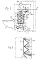
- the vacuum toilet system shown is intended for installation in a passenger transport unit such as a railroad car, a bus or the like. Vacuum is generated separately just before each emptying of the toilet bowl.
- the system includes a toilet with a toilet bowl 1 that is connected to a short sewer pipe 3 through a normally-closed sewer valve 2.
- the sewer pipe 3 is in free connection with a portion 7 of variable volume in a chamber 9 and is closed at its downstream end by a valve 4 that separates the short sewer pipe 3 from an extension 5 thereof that leads to a collection tank, an outlet or the like (not shown).
- the inner space of the chamber 9 is divided by a movable rubber membrane 11 into two portions, a portion 7 (which is an unclean portion) and a clean portion 14.
- the vacuum generator of the system is an ejector 8 that extracts air from the clean portion 14 through an evacuation duct 10.
- the ejector 8 is driven by pressurized air received from a compressed air network 17 via a solenoid valve 12.
- the compressed air network 17 is also connected to another solenoid valve 16 operable to pressurize the clean portion 14 of the pressure chamber with compressed air.
- the air feed duct 18 of the ejector is controlled by the valve 12 and the evacuation duct 10 is controlled by a solenoid valve 6.
- the flow duct passing through the valve 16 is provided with a pressure reduction means 16a. All the valves mentioned are remote controlled.
- a flush button 13 arranged at or near the toilet bowl 1 is connected to a control unit 24 that controls the different functions of the system by operating the remote controlled valves of the system.
- a toilet emptying sequence is started by operating the flush button 13. Thereby an impulse is sent to the control unit 24 which opens the valve 12 and allows compressed air to flow through the ejector 8. This creates, in a few seconds, a partial vacuum of approximately 60% of atmospheric pressure (absolute pressure approximately 0,4 bar) in the clean portion 14 of the chamber 9, which moves the membrane 11 upwards to a pressure balance position lla creating essentially the same vacuum in the space portion 7.
- the sewer valve 2 is now rapidly opened and the waste present in the toilet bowl 1 is instantaneously pressed by the atmospheric pressure into the sewer pipe 3. This causes a rise in pressure in the pipe 3 and in the space portion 7, that causes the membrane 11 to move further upwards to a position 11b. This second movement will be faster and more positive if the ejector 8 is still operating during this phase.
- a less favourable alternative is to disconnect the ejector 8 when the maximum vacuum level has been reached and the valves 6 and 16 are kept closed.
- the sewer valve 2 When all the waste has been removed from the toilet bowl 1, the sewer valve 2 is closed and the valve 4 is opened. The sewage present in the pipe 3 and the space portion 7 may now flow into the pipe 5. Further transport of the waste material may be enhanced by pressurizing the portion 14 of the chamber 9.
- An alternative is to provide a pressure spring 19 urging the membrane 11 downwards and/or to use a membrane that itself functions as a pressure spring. In that case pressurizing of the space 7 is obtained merely by closing down the ejector 8 and by keeping the valve 6 open, provided that the ejector 8 allows ambient air to flow into the portion 14 when the ejector is closed down. If this is not possible, another air flow duct must be provided. If the portion 7 is not pressurized, or is pressurized only by means of a spring force, the valve 6 may be totally omitted as well as the valve 16 and its piping.
- a bottom portion 15 of the membrane 11, forming the upper boundary of the space portion 7, is preferably made of thicker material. It may then provide a suitable support for a pressure spring 19 arranged to urge the membrane 11 downwards should such a spring be required.
- Fig. 2 shows how each outer fold of the membrane 11 can be provided with a strengthening ring 20 of steel or some other suitable material. Without such rings, the outer diameter of the folds can decrease during axial expansion of the membrane so that contact between the membrane folds and the wall of the chamber 9 will be lost.
- the rings 20 keep the outer diameter of the folds practically constant.
- the toilet bowl 1 In connection with an emptying sequence, the toilet bowl 1 is provided with a desired amount of rinse liquid for rinsing and cleaning the inner surface of the bowl. This arrangement is not illustrated because it is known art and is not part of the inventive concept.
Landscapes
- Engineering & Computer Science (AREA)
- Health & Medical Sciences (AREA)
- Life Sciences & Earth Sciences (AREA)
- Hydrology & Water Resources (AREA)
- Public Health (AREA)
- Water Supply & Treatment (AREA)
- Aviation & Aerospace Engineering (AREA)
- Separation Using Semi-Permeable Membranes (AREA)
- Sanitary Device For Flush Toilet (AREA)
- Sewage (AREA)
- Casting Or Compression Moulding Of Plastics Or The Like (AREA)
- Control Of Fluid Pressure (AREA)
Claims (10)
- Système d'évacuation à vide comprenant au moins une unité de production de déchets (1), par exemple une cuvette de W.C., comportant une ouverture de décharge et une vanne d'évacuation normalement fermée (2) près de l'ouverture de décharge, laquelle vanne d'évacuation relie directement l'unité (1) à l'extrémité amont d'une conduite d'évacuation courte (3) comportant, au niveau de son extrémité aval, une autre vanne normalement fermée (4) et qui est, entre les vannes (2, 4), en communication avec une chambre (7) de volume variable, laquelle chambre, ainsi que la conduite d'évacuation (3), est munie d'un moyen destiné à engendrer dans celle-ci, lorsque lesdites vannes (2, 4) sont fermées, un vide partiel d'une amplitude telle que des déchets provenant de l'unité (1), d'une façon instantanée, sont repoussés jusque dans la conduite d'évacuation (3) par la pression de l'air ambiant lorsque la vanne d'évacuation (2) est ouverte, caractérisé en ce que le moyen destiné à engendrer un vide partiel comprend une chambre de pression (9), divisée par une membrane souple (11) pouvant être déplacée dans celle-ci, en deux parties (7, 14) séparées l'une de l'autre, dont une première partie (7) forme la chambre de volume variable reliée à la conduite d'évacuation (3) et une seconde partie (14) au niveau du côté opposé de la membrane (11) forme une chambre commandée par pression (14) reliée à un moyen (8) destiné à faire varier la pression dans celle-ci, ledit moyen (8) permettant une réduction de la pression de fonctionnement dans la seconde partie (14) jusqu'à un vide partiel afin de déplacer la membrane (11), lorsque lesdites vannes (2, 4) sont fermées, jusqu'à une position équilibrée en pression déterminée de façon fondamentale par la différence de pression régnant entre les côtés opposés de la membrane (11), en créant ainsi, dans la première partie (7) de la chambre de pression ainsi que dans la conduite d'évacuation (3), un vide partiel suffisant pour le transport des déchets depuis l'unité de production de déchets (1), et permettant en outre, au cours d'une phase ultérieure, une augmentation de la pression de fonctionnement, lorsque la vanne d'évacuation (2) est fermée et que ladite autre vanne (4) au niveau de l'extrémité aval de la conduite d'évacuation (3) est ouverte, grâce à quoi la membrane (11) est amenée à revenir vers la position initiale, en engendrant ainsi, si la membrane est chargée, une surpression dans la conduite d'évacuation (3) destinée à faciliter un transport supplémentaire des déchets présents dans la conduite d'évacuation (3) au moyen de ladite surpression.
- Système selon la revendication 1, caractérisé en ce que, quand la membrane (11) se trouve dans sa position d'équilibre de pression, il se trouve une partie d'espace libre (14) au niveau du côté de pression de fonctionnement de la membrane permettant que la membrane (11) se déplace davantage dans une direction qui agrandit la première partie (7) de la chambre de pression, lorsque la pression régnant dans la première partie (7) augmente sous l'influence des déchets et de l'air pénétrant dans la conduite d'évacuation (3) pendant que la vanne d'évacuation (2) est ouverte.
- Système selon la revendication 1 ou 2, caractérisé en ce que la membrane (11) présente une liberté de mouvement qui permet des variations de volume dans la chambre de pression (9), de chaque côté de la membrane (11), dans la plage de 2 à 15 litres, de préférence de 5 à 10 litres.
- Système selon l'une quelconque des revendications précédentes, caractérisé en ce que le moyen assurant un actionnement par pression de la membrane comprend un dispositif (8) destiné à appliquer un vide partiel, lequel dispositif (8) est conçu pour être en fonctionnement pendant au moins pratiquement la totalité de la durée pendant laquelle la vanne d'évacuation (2) est ouverte, et est de préférence conçu pour diminuer la pression de fonctionnement agissant sur la membrane (11) jusqu'à au moins approximativement la moitié de la pression de l'air ambiant.
- Système selon l'une quelconque des revendications précédentes, caractérisé en ce que le moyen (8) destiné à engendrer un vide partiel dans la conduite d'évacuation (3) est conçu pour être mis en fonction immédiatement avant chaque vidange souhaitée de l'unité (1).
- Système selon l'une quelconque des revendications précédentes, caractérisé en ce que le système comprend un éjecteur alimenté par air (8) en tant que source de vide partiel.
- Système selon l'une quelconque des revendications précédentes, caractérisé en ce que la membrane présente la forme d'un soufflet replié (11) se déplaçant suivant l'axe dans une chambre de pression pratiquement cylindrique (9), les plis du soufflet recevant de préférence un guidage en venant en contact avec la surface cylindrique interne de la chambre de pression (9).
- Système selon la revendication 7, caractérisé en ce qu'au moins certains des plis orientés vers l'extérieur du soufflet (11) sont munis d'anneaux de renfort (20) ou analogues, qui amènent le diamètre extérieur des plis à rester pratiquement constants pendant le déplacement du soufflet.
- Système selon la revendication 7 ou 8, caractérisé en ce que le soufflet, au niveau de son extrémité mobile en regard de la première partie (7) de la chambre de pression, est muni d'une lèvre périphérique souple (21) coulissant contre la surface interne de la chambre de pression (9).
- Système selon l'une quelconque des revendications précédentes, caractérisé en ce que la membrane (11) agit elle-même en tant qu'élément de ressort, ou bien est chargée par un élément de ressort (19), en direction de la première partie (7) de la chambre de pression, en provoquant ainsi une surpression dans celle-ci ainsi que dans la conduite d'évacuation (3) lorsque la pression de fonctionnement agissant sur la membrane (11) est la même ou pratiquement la même que la pression de l'air ambiant.
Priority Applications (4)
| Application Number | Priority Date | Filing Date | Title |
|---|---|---|---|
| EP95306394A EP0763633B1 (fr) | 1995-09-13 | 1995-09-13 | Système d'égout à vide réglé par une membrane |
| DK95306394T DK0763633T3 (da) | 1995-09-13 | 1995-09-13 | Membranstyret vakuumkloaksystem |
| AT95306394T ATE183795T1 (de) | 1995-09-13 | 1995-09-13 | Von einer membran reguliertes vakuumabwassersystem |
| DE69511695T DE69511695T2 (de) | 1995-09-13 | 1995-09-13 | Von einer Membran reguliertes Vakuumabwassersystem |
Applications Claiming Priority (1)
| Application Number | Priority Date | Filing Date | Title |
|---|---|---|---|
| EP95306394A EP0763633B1 (fr) | 1995-09-13 | 1995-09-13 | Système d'égout à vide réglé par une membrane |
Publications (2)
| Publication Number | Publication Date |
|---|---|
| EP0763633A1 EP0763633A1 (fr) | 1997-03-19 |
| EP0763633B1 true EP0763633B1 (fr) | 1999-08-25 |
Family
ID=8221320
Family Applications (1)
| Application Number | Title | Priority Date | Filing Date |
|---|---|---|---|
| EP95306394A Expired - Lifetime EP0763633B1 (fr) | 1995-09-13 | 1995-09-13 | Système d'égout à vide réglé par une membrane |
Country Status (4)
| Country | Link |
|---|---|
| EP (1) | EP0763633B1 (fr) |
| AT (1) | ATE183795T1 (fr) |
| DE (1) | DE69511695T2 (fr) |
| DK (1) | DK0763633T3 (fr) |
Cited By (2)
| Publication number | Priority date | Publication date | Assignee | Title |
|---|---|---|---|---|
| US8490223B2 (en) | 2011-08-16 | 2013-07-23 | Flow Control LLC | Toilet with ball valve mechanism and secondary aerobic chamber |
| EP3699088B1 (fr) * | 2019-02-19 | 2023-08-09 | B/E Aerospace, Inc. | Système de déchets sous vide |
Families Citing this family (7)
| Publication number | Priority date | Publication date | Assignee | Title |
|---|---|---|---|---|
| FI105120B (fi) * | 1998-12-23 | 2000-06-15 | Evac Int Oy | Jätteen kuljetusjärjestelmä |
| EP1354101B1 (fr) | 2001-01-26 | 2008-03-26 | Geberit Technik Ag | Systeme de toilettes dote d'une cuvette de toilettes |
| FI110536B (fi) * | 2001-06-21 | 2003-02-14 | Evac Int Oy | Menetelmä jäteaineen kuljettamiseksi alipaineviemärijärjestelmässä |
| DE20301649U1 (de) * | 2003-02-03 | 2004-06-17 | Evac Gmbh | Vakuumtoilette |
| FI118231B (fi) * | 2006-01-30 | 2007-08-31 | Evac Int Oy | Alipaineviemärijärjestelmä |
| JP6034076B2 (ja) * | 2012-06-19 | 2016-11-30 | 福島 寿蔵 | 簡易便槽タンクと汚水回収システム |
| EP3321439A1 (fr) | 2016-11-15 | 2018-05-16 | Alte Technologies S.L.U. | Système de transfert de déchets pour toilettes d'un véhicule de transport public |
Family Cites Families (7)
| Publication number | Priority date | Publication date | Assignee | Title |
|---|---|---|---|---|
| US2865028A (en) * | 1955-10-04 | 1958-12-23 | Verne L Patenaude | Sewage system for mobile homes and the like |
| US4184506A (en) | 1973-12-29 | 1980-01-22 | Krister Nordberg | Vacuum sewer system |
| SE389882B (sv) | 1975-04-23 | 1976-11-22 | Ifoe Ab | Anordning vid vakuumklosett med uppsamlingsbehallare |
| FI66670C (fi) | 1978-08-25 | 1985-02-01 | Waertsilae Oy Ab | Avloppssystem |
| FR2516119A1 (fr) * | 1981-11-06 | 1983-05-13 | Soterkenos Sarl | Installation d'ecoulement d'un fluide notamment pour l'evacuation des eaux usees |
| DE9111247U1 (fr) * | 1991-09-11 | 1992-04-23 | Semco A/S C/O Semco Odense A/S, Odense, Dk | |
| SE469832B (sv) | 1992-02-05 | 1993-09-27 | Evac Ab | Vakuumtoalettsystem med luktfilter |
-
1995
- 1995-09-13 AT AT95306394T patent/ATE183795T1/de not_active IP Right Cessation
- 1995-09-13 EP EP95306394A patent/EP0763633B1/fr not_active Expired - Lifetime
- 1995-09-13 DE DE69511695T patent/DE69511695T2/de not_active Expired - Fee Related
- 1995-09-13 DK DK95306394T patent/DK0763633T3/da active
Cited By (2)
| Publication number | Priority date | Publication date | Assignee | Title |
|---|---|---|---|---|
| US8490223B2 (en) | 2011-08-16 | 2013-07-23 | Flow Control LLC | Toilet with ball valve mechanism and secondary aerobic chamber |
| EP3699088B1 (fr) * | 2019-02-19 | 2023-08-09 | B/E Aerospace, Inc. | Système de déchets sous vide |
Also Published As
| Publication number | Publication date |
|---|---|
| ATE183795T1 (de) | 1999-09-15 |
| DE69511695D1 (de) | 1999-09-30 |
| DE69511695T2 (de) | 1999-12-23 |
| DK0763633T3 (da) | 2000-03-20 |
| EP0763633A1 (fr) | 1997-03-19 |
Similar Documents
| Publication | Publication Date | Title |
|---|---|---|
| EP0763633B1 (fr) | Système d'égout à vide réglé par une membrane | |
| EP1013838B1 (fr) | Dispositif de transport d'eaux usées | |
| JP3100992B2 (ja) | 真空トイレット装置 | |
| JP5519900B2 (ja) | 真空式下水システム | |
| US6085366A (en) | Apparatus for supplying pressurized rinse water to a toilet | |
| JPH07207745A (ja) | 真空式下水装置 | |
| US3746032A (en) | Pneumatic liquid disposal system | |
| EP2143848A1 (fr) | Système d'aspiration d'air pour canal de vidange de toilettes | |
| JPH08503035A (ja) | 負圧トイレシステムとその排出弁 | |
| EP4164769A1 (fr) | Agencement de soupape pour un extracteur de poussière industrielle | |
| US6279176B1 (en) | Low water toilet | |
| CA2032882A1 (fr) | Montage pour le transport sous vide des eaux d'egout | |
| JP3647497B2 (ja) | 弁組立体 | |
| JP2006112057A (ja) | 便器装置 | |
| SE506005C2 (sv) | Membranstyrt vakuumavloppsystem | |
| US4621379A (en) | Flushing operating means for vacuum toilet | |
| KR20010013299A (fr) | Systeme de toilettes a aspiration par le vide | |
| EP0217185B1 (fr) | Clapet d'écoulement pour toilette d'acion | |
| WO2019236022A1 (fr) | Système de toilettes pouvant être caché compatible avec des systèmes de pompe à vide ou broyeuse | |
| JP2000096698A (ja) | 真空弁強制作動機器 | |
| JP2586279B2 (ja) | 真空弁ユニット | |
| EP0848239A3 (fr) | Système et procédé d'inspection et d'essai d'un tube de fumée | |
| EP4153819A1 (fr) | Toilette | |
| GB2552561A (en) | Fluid deployment apparatus and method | |
| AU8082491A (en) | A fluid valve device and a positive-displacement pump |
Legal Events
| Date | Code | Title | Description |
|---|---|---|---|
| PUAI | Public reference made under article 153(3) epc to a published international application that has entered the european phase |
Free format text: ORIGINAL CODE: 0009012 |
|
| AK | Designated contracting states |
Kind code of ref document: A1 Designated state(s): AT CH DE DK FR IT LI |
|
| 17P | Request for examination filed |
Effective date: 19970619 |
|
| 17Q | First examination report despatched |
Effective date: 19971013 |
|
| GRAG | Despatch of communication of intention to grant |
Free format text: ORIGINAL CODE: EPIDOS AGRA |
|
| GRAG | Despatch of communication of intention to grant |
Free format text: ORIGINAL CODE: EPIDOS AGRA |
|
| GRAH | Despatch of communication of intention to grant a patent |
Free format text: ORIGINAL CODE: EPIDOS IGRA |
|
| GRAH | Despatch of communication of intention to grant a patent |
Free format text: ORIGINAL CODE: EPIDOS IGRA |
|
| GRAA | (expected) grant |
Free format text: ORIGINAL CODE: 0009210 |
|
| AK | Designated contracting states |
Kind code of ref document: B1 Designated state(s): AT CH DE DK FR IT LI |
|
| REF | Corresponds to: |
Ref document number: 183795 Country of ref document: AT Date of ref document: 19990915 Kind code of ref document: T |
|
| REG | Reference to a national code |
Ref country code: CH Ref legal event code: EP |
|
| ITF | It: translation for a ep patent filed |
Owner name: INTERPATENT ST.TECN. BREV. |
|
| REF | Corresponds to: |
Ref document number: 69511695 Country of ref document: DE Date of ref document: 19990930 |
|
| REG | Reference to a national code |
Ref country code: CH Ref legal event code: NV Representative=s name: A. BRAUN, BRAUN, HERITIER, ESCHMANN AG PATENTANWAE |
|
| ET | Fr: translation filed | ||
| REG | Reference to a national code |
Ref country code: DK Ref legal event code: T3 |
|
| PLBE | No opposition filed within time limit |
Free format text: ORIGINAL CODE: 0009261 |
|
| STAA | Information on the status of an ep patent application or granted ep patent |
Free format text: STATUS: NO OPPOSITION FILED WITHIN TIME LIMIT |
|
| 26N | No opposition filed | ||
| PGFP | Annual fee paid to national office [announced via postgrant information from national office to epo] |
Ref country code: DK Payment date: 20020813 Year of fee payment: 8 |
|
| PGFP | Annual fee paid to national office [announced via postgrant information from national office to epo] |
Ref country code: AT Payment date: 20030807 Year of fee payment: 9 |
|
| PGFP | Annual fee paid to national office [announced via postgrant information from national office to epo] |
Ref country code: FR Payment date: 20030811 Year of fee payment: 9 |
|
| PGFP | Annual fee paid to national office [announced via postgrant information from national office to epo] |
Ref country code: CH Payment date: 20030818 Year of fee payment: 9 |
|
| PGFP | Annual fee paid to national office [announced via postgrant information from national office to epo] |
Ref country code: DE Payment date: 20030821 Year of fee payment: 9 |
|
| PG25 | Lapsed in a contracting state [announced via postgrant information from national office to epo] |
Ref country code: DK Free format text: LAPSE BECAUSE OF NON-PAYMENT OF DUE FEES Effective date: 20030930 |
|
| REG | Reference to a national code |
Ref country code: DK Ref legal event code: EBP |
|
| PG25 | Lapsed in a contracting state [announced via postgrant information from national office to epo] |
Ref country code: AT Free format text: LAPSE BECAUSE OF NON-PAYMENT OF DUE FEES Effective date: 20040913 |
|
| PG25 | Lapsed in a contracting state [announced via postgrant information from national office to epo] |
Ref country code: LI Free format text: LAPSE BECAUSE OF NON-PAYMENT OF DUE FEES Effective date: 20040930 Ref country code: CH Free format text: LAPSE BECAUSE OF NON-PAYMENT OF DUE FEES Effective date: 20040930 |
|
| PG25 | Lapsed in a contracting state [announced via postgrant information from national office to epo] |
Ref country code: DE Free format text: LAPSE BECAUSE OF NON-PAYMENT OF DUE FEES Effective date: 20050401 |
|
| REG | Reference to a national code |
Ref country code: CH Ref legal event code: PL |
|
| PG25 | Lapsed in a contracting state [announced via postgrant information from national office to epo] |
Ref country code: FR Free format text: LAPSE BECAUSE OF NON-PAYMENT OF DUE FEES Effective date: 20050531 |
|
| REG | Reference to a national code |
Ref country code: FR Ref legal event code: ST |
|
| PG25 | Lapsed in a contracting state [announced via postgrant information from national office to epo] |
Ref country code: IT Free format text: LAPSE BECAUSE OF NON-PAYMENT OF DUE FEES;WARNING: LAPSES OF ITALIAN PATENTS WITH EFFECTIVE DATE BEFORE 2007 MAY HAVE OCCURRED AT ANY TIME BEFORE 2007. THE CORRECT EFFECTIVE DATE MAY BE DIFFERENT FROM THE ONE RECORDED. Effective date: 20050913 |