EP0763409A2 - Feed arrangement for bulk material - Google Patents
Feed arrangement for bulk material Download PDFInfo
- Publication number
- EP0763409A2 EP0763409A2 EP96110334A EP96110334A EP0763409A2 EP 0763409 A2 EP0763409 A2 EP 0763409A2 EP 96110334 A EP96110334 A EP 96110334A EP 96110334 A EP96110334 A EP 96110334A EP 0763409 A2 EP0763409 A2 EP 0763409A2
- Authority
- EP
- European Patent Office
- Prior art keywords
- opening
- loading
- bucket
- filling funnel
- filling
- Prior art date
- Legal status (The legal status is an assumption and is not a legal conclusion. Google has not performed a legal analysis and makes no representation as to the accuracy of the status listed.)
- Granted
Links
Images
Classifications
-
- B—PERFORMING OPERATIONS; TRANSPORTING
- B28—WORKING CEMENT, CLAY, OR STONE
- B28C—PREPARING CLAY; PRODUCING MIXTURES CONTAINING CLAY OR CEMENTITIOUS MATERIAL, e.g. PLASTER
- B28C7/00—Controlling the operation of apparatus for producing mixtures of clay or cement with other substances; Supplying or proportioning the ingredients for mixing clay or cement with other substances; Discharging the mixture
- B28C7/04—Supplying or proportioning the ingredients
- B28C7/06—Supplying the solid ingredients, e.g. by means of endless conveyors or jigging conveyors
- B28C7/08—Supplying the solid ingredients, e.g. by means of endless conveyors or jigging conveyors by means of scrapers or skips
- B28C7/0835—Supplying the solid ingredients, e.g. by means of endless conveyors or jigging conveyors by means of scrapers or skips using skips to be hoisted along guides or to be tilted, to charge working-site concrete mixers
- B28C7/0841—Supplying the solid ingredients, e.g. by means of endless conveyors or jigging conveyors by means of scrapers or skips using skips to be hoisted along guides or to be tilted, to charge working-site concrete mixers having mechanisms to fill the skip in its lowest position, e.g. by drag shovels, from a hopper
Abstract
Description
Die Erfindung betrifft eine Einrichtung zum Beschicken eines Mischkessels mit Schüttgut, insbesondere mit Baustoffen, wie Sand, Kies, Zement und/oder Feinbeton, mit einem den Mischkessel tragenden Maschinengestell, mit einer am Mischkessel angeordneten, nach oben weisenden, vorzugsweise mittels eines Verschlußdeckels druckdicht verschließbaren Beschickungsöffnung und mit einem am Maschinengestell um eine horizontale gestellfeste Schwenkachse zwischen einer abgesenkten Einfüllstellung und einer angehobenen Entleerstellung mit hydraulischen oder motorischen Mitteln begrenzt verschwenkbaren, eine Einfüllöffnung und eine zur kesselseitigen Beschickungsöffnung weisende, in der angehobenen Entleerstellung in diese mündende trichterförmige Entleeröffnung aufweisenden Beschickungskübel.The invention relates to a device for loading a mixing vessel with bulk material, in particular with building materials such as sand, gravel, cement and / or fine concrete, with a machine frame supporting the mixing vessel, with an upward-facing, preferably pressure-tightly closable lid arranged on the mixing vessel Loading opening and with a pivoting pivot on the machine frame about a horizontal pivot axis fixed to the frame between a lowered filling position and a raised emptying position with hydraulic or motor means, a filling opening and a loading bucket pointing towards the boiler-side loading opening and having a funnel-shaped emptying opening that opens into this funnel-shaped emptying opening.
Beschickungseinrichtungen dieser Art (DE-OS 44 40 335) werden vor allem bei Druckluftförderern für Baustoffe eingesetzt, die einen Misch- und Druckkessel mit einer relativ kleinen Einfüllöffnung aufweisen, in die der Beschickungskübel in der angehobenen Entleerstellung mit seiner trichterförmigen Entleeröffnung unmittelbar einmündet. Der Mischkessel wird über seine Einfüllöffnung mit Zement, Sand und Wasser in einem vorgegebenen Mengenverhältnis beschickt. Das Gemisch wird nach erfolgter Durchmischung bei geschlossener Einfüllöffnung unter Einwirkung von Druckluft an eine externe Verarbeitungsstelle gefördert. Die kesselseitige Einfüllöffnung ist konstruktionsbedingt relativ klein. Es ist daher recht schwierig, das Schüttgut aus dem Beschickungskübel verlustfrei in den Mischkessel zu praktizieren, da eine ausreichend feinfühlige Dosierung des Materialflusses durch Veränderung des Schüttwinkels nicht möglich ist. Hinzu kommt, daß bei der bekannten Druckförderanlage sowohl Sand als auch Zement über den Beschickungskübel dem Kessel zugeführt wird. Der Beschickungskübel weist zu diesem Zweck eine Aufreißkante für Zementsäcke auf. Wenn in einem solchen Fall nicht das gesamte Material aus dem Beschickungskübel in den Mischkessel übergeben wird, besteht die Gefahr, daß es zu Fehldosierungen kommt, die daher rühren, daß entweder zuviel Zement oder zuviel Sand aus dem Beschickungskübel in den Kessel gelangt. Hinzu kommt, daß bei feuchter Witterung oder bei Regen es zu Verbackungen von Zement und Sand im Beschickungskübel kommen kann, die allmählich zu festen Ablagerungen und zu Funktionsstörungen führen können. Um dies zu vermeiden, ist es erwünscht, die Zumischung von Zement nicht über den Beschickungskübel, sondern direkt in den Mischkessel vorzunehmen. Die kesselseitige Beschickungsöffnung eignet sich hierfür jedoch wegen der beschränkten Öffnungsweite und einer fehlenden Aufreißvorrichtung für die Zementsäcke nicht.Feeding devices of this type (DE-OS 44 40 335) are used above all in compressed air conveyors for building materials which have a mixing and pressure vessel with a relatively small filling opening, into which the loading bucket opens directly with its funnel-shaped emptying opening in the raised emptying position. The mixing kettle is filled with cement, sand and water in a predetermined ratio through its fill opening. After thorough mixing, the mixture is opened with the filling opening closed conveyed to an external processing station under the influence of compressed air. The filler opening on the boiler side is relatively small due to its design. It is therefore quite difficult to transfer the bulk material from the loading bucket into the mixing tank without loss, since a sufficiently sensitive metering of the material flow by changing the angle of repose is not possible. In addition, in the known pressure conveyor system, both sand and cement are fed to the boiler via the loading bucket. For this purpose, the loading bucket has a tear-open edge for cement bags. In such a case, if not all of the material from the feed bucket is transferred to the mixing kettle, there is a risk that incorrect dosing will result from either too much cement or too much sand coming from the feed bucket into the kettle. In addition, in damp weather or in the rain, caking of cement and sand in the loading bucket can occur, which can gradually lead to solid deposits and malfunctions. To avoid this, it is desirable not to add cement via the feed bucket, but directly into the mixing tank. The boiler-side loading opening is not suitable for this, however, because of the limited opening width and the lack of a tear-open device for the cement bags.
Ausgehend hiervon liegt der Erfindung die Aufabe zugrunde, eine Beschickungseinrichtung der eingangs angegebenen Art zu entwickeln, mit der eine fehlerfreie Dosierung des Schüttguts ohne die Gefahr des Überfließens erzielt werden kann.Proceeding from this, the invention is based on the task of a loading device of the type specified at the beginning To develop a way with which an accurate dosing of the bulk material can be achieved without the risk of overflowing.
Zur Lösung dieser Aufgabe wird die im Patentanspruch 1 angegebene Merkmalskombination vorgeschlagen. Vorteilhafte Ausgestaltungen und Weiterbildungen der Erfindung ergeben sich aus den Unteransprüchen.To achieve this object, the combination of features specified in claim 1 is proposed. Advantageous refinements and developments of the invention result from the subclaims.
Die erfindungsgemäße Lösung geht von dem Gedanken aus, daß durch die Verwendung eines zusätzlichen, um die Kippachse des Beschickungskübels oder um eine dazu parallele Achse gegenüber dem Maschinengestell und dem Beschickungskübel begrenzt verschwenkbaren Einfülltrichters, der eine der kübelseitigen Entleeröffnung zugewandte Eintrittsöffnung und eine der kesselseitigen Einfüllöffnung zugewandte Austrittsöffnung aufweist, ein rasches und sauberes Entleeren des Beschickungskübels in den Mischkessel möglich ist und daß weitere Mischungsbestandteile, wie Zement, Glasfasern und Wasser, bei abgehobenem Beschickungskübel über den Einfülltrichter in den Kessel eindosiert werden können.The solution according to the invention is based on the idea that by using an additional hopper which can be pivoted to a limited extent about the tilting axis of the loading bucket or about an axis parallel to it, relative to the machine frame and the loading bucket, which has an inlet opening facing the bucket-side emptying opening and one facing the boiler-side filling opening Has outlet opening, a quick and clean emptying of the feed bucket into the mixing tank is possible and that other mixture components, such as cement, glass fibers and water, can be metered into the tank via the filling funnel when the loading bucket is lifted off.
Eine bevorzugte Ausgestaltung der Erfindung sieht vor, daß der Einfülltrichter mit dem Beschickungskübel über ein Verbindungselement so gekoppelt ist, daß in der angehobenen Entleerstellung des Beschickungskübels die Entleeröffnung des Beschickungskübels unmittelbar in die Eintrittsöffnung des Einfülltrichters und die Austrittsöffnung des Einfülltrichters unmittelbar in die kesselseitige Beschickungsöffnung mündet, daß in einer Zwischenstellung der Beschickungskübel von der Eintrittsöffnung des mit seiner Austrittsöffnung in die kesselseitige Beschickungsöffnung mündenden Einfülltrichters abgehoben ist und daß in der abgesenkten Einfüllstellung des Beschickungskübels der Einfülltrichter unter Freigabe der kesselseitigen Beschickungsöffnung vom Mischkessel abgehoben ist. Dieser Bewegungsablauf wird mit besonders einfachen Mitteln dadurch ermöglicht, daß der Einfülltrichter über ein biegsames oder biegeschlaffes Verbindungselement, beispielsweise über ein Seil oder eine Kette, mit dem Beschickungskübel verbunden ist. Der Einfülitrichter ist dabei zweckmäßig zwischen einem kesselseitigen Endanschlag und einem kübelseitigen Endanschlag verschwenkbar, wobei der Einfülltrichter unter der Einwirkung seines Eigengewichts gegen die vorzugsweise gummigepufferten Endanschläge anliegt. Beim Kippen des Beschickungsteils in der einen oder anderen Richtung wird der Einfülltrichter zweckmäßig unter der Einwirkung des Verbindungselements oder des gegen ihn anliegenden Beschickungskübels über einen oberen Totpunkt verschwenkt. Das Abheben des Einfülltrichters von der kesselseitigen Beschickungsöffnung erfolgt beim Abwärtskippen des Beschickungskübels von der Zwischenstellung aus unter der Einwirkung des Verbindungselements. Die Zudosierung von Zement kann bei in der Zwischenstellung befindlichem Beschickungskübel unmittelbar über den Einfülltrichter erfolgen. Der Einfülltrichter kann zu diesem Zweck mit einer in Richtung Eintrittsöffnung weisenden Aufreißkante für Zementsäcke versehen sein. Zweckmäßig wird die Zwischenstellung des Beschickungskübels so gewählt, daß sich in dem im Beschickungskübel befindlichen Schüttgut bereits ein Schüttwinkel einstellt, der zu einer Teilentleerung in den Mischkessel führt. Wichtig ist hierfür, daß der Beschickungsbehälter mit seiner Entleeröffnung auch schon in der die Eintrittsöffnung des Einfülltrichters freilassenden Zwischenstellung in den Einfülltrichter mündet.A preferred embodiment of the invention provides that the filling funnel is coupled to the loading bucket via a connecting element so that in the raised emptying position of the loading bucket, the emptying opening of the loading bucket directly into the inlet opening of the filling funnel and the outlet opening of the filling funnel directly into the boiler-side loading opening opens, that in an intermediate position the loading bucket is lifted from the inlet opening of the filling funnel opening into the boiler-side loading opening and that in the lowered filling position of the loading bucket the filling funnel is lifted off the mixing vessel, releasing the loading opening on the boiler side. This sequence of movements is made possible with particularly simple means in that the filling funnel is connected to the loading bucket via a flexible or pliable connection element, for example via a rope or a chain. The filling funnel is expediently pivotable between an end stop on the boiler side and an end stop on the bucket side, the filling funnel resting against the preferably rubber-buffered end stops under the influence of its own weight. When the loading part is tilted in one direction or the other, the filling funnel is expediently pivoted over an upper dead center under the action of the connecting element or the loading bucket lying against it. The hopper is lifted from the tank-side loading opening when the loading bucket is tipped down from the intermediate position under the action of the connecting element. The cement can be added directly via the hopper when the bucket is in the intermediate position. For this purpose, the filling funnel can have a tear-open edge for cement bags pointing in the direction of the inlet opening be provided. The intermediate position of the feed bucket is expediently chosen such that a pour angle is already established in the bulk material in the feed bucket, which leads to partial emptying into the mixing vessel. It is important for this that the loading container with its emptying opening also opens into the filling funnel in the intermediate position that leaves the inlet opening of the filling funnel.
Eine weitere vorteilhafte Ausgestaltung der Erfindung sieht vor, daß der Verschlußdeckel um eine zur gemeinsamen Kipp- und Schwenkachse des Beschickungskübels und des Einfülltrichters quer verlaufende gestellfeste Klappachse verschwenkbar ist.A further advantageous embodiment of the invention provides that the closure lid can be pivoted about a folding axis fixed to the frame and extending transversely to the common tilting and swiveling axis of the charging bucket and the filling funnel.
Im folgenden wird die Erfindung anhand eines in der Zeichnung in schematischer Weise dargestellten Ausführungsbeispiels näher erläutert. Es zeigen
- Fig. 1 bis 8
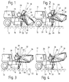
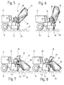
- einen Druckluftförderer mit einer Beschickungseinrichtung für Schüttgut in verschiedenen Stellungen der Beschickungseinrichtung während des Beschickungsvorgangs.
- 1 to 8
- a compressed air conveyor with a loading device for bulk material in different positions of the loading device during the loading process.
Der in der Zeichnung dargestellte Druckluftförderer besteht im wesentlichen aus einem einachsigen Fahrgestell 10, auf welchem ein Kompressor 12, ein Mischkessel 14 und eine dem Mischkessel 14 zugeordnete Beschickungseinrichtung 16 für Schüttgut angeordnet ist. Das Fahrgestell 10 ist mit zwei mischkesselseitigen Stützbeinen 20 auf dem Boden 22 abstützbar. Der Mischkessel 14 ist an seiner Oberseite mit einer Beschickungsöffnung 24 versehen, die mit einem Verschlußdeckel 26 zu Misch- und Förderzwecken druckdicht verschließbar ist. Zur Beschickung des Mischkessels 14 mit Sand, Kies, Zement oder Feinbeton dient die Beschickungseinrichtung 16, die einen um eine gesteilfeste Kippachse 28 mittels eines Hydrozylinders 30 am Fahrgestell 10 verschwenkbaren Beschickungskübel 32 sowie einen um die Kippachse 28 verschwenkbaren Einfülltrichter 34 aufweist. Der Beschickungskübel 32 und der Einfülltrichter 34 sind über ein quer zur Kippachse 28 ausgerichtetes, biegeschlaffes Metallseil 36 miteinander verbunden und führen daher beim Beschickungsvorgang eine gekoppelte Kipp- und Schwenkbewegung aus. Der Beschickungskübel weist eine Einfüllöffnung 38 und eine in Richtung Einfülltrichter 34 weisende tricherförmige Entleeröffnung 40 auf, während der Einfülltrichter 34 eine kübelseitige Eintrittsöffnung 42 und eine kesselseitige Austrittsöffnung 44 aufweist. Beim Beschickungsvorgang ist der Verschlußdeckel 26 der kesselseitigen Beschickungsöffnung 24 offen. Der Bewegungsablauf beim Beschickungsvorgang ist wie folgt:The compressed air conveyor shown in the drawing essentially consists of a
Der Beschickungskübel 32 wird in seiner in Fig. 1 dargestellten abgesenkten Endstellung über die Einfüllöffnung 38 von Hand mit einer Schaufel oder Schrapperschaufel gefüllt. In dieser Stellung ist der Einfülltrichter 34 von der Beschickungsöffnung 24 des Mischkessels 14 abgehoben und liegt unter der Einwirkung der Schwerkraft gegen einen kübelseitigen Anschlag 46 an, während das Verbindungsseil 36 durchhängt.In its lowered end position shown in FIG. 1, the
Sobald der Beschickungskübel 32 voll ist, wird er durch Betätigen des Hydrozylinders 30 von seiner unteren Endstellung (Fig. 1) allmählich in seine obere Endstellung (Fig. 6) um die Kippachse 28 geschwenkt. Er nimmt dabei den Einfülltrichter 34 mit. Dieser erreicht in der in Fig. 2 gezeigten Zwischenstellung mit noch durchhängendem Verbindungsseil 36 seinen oberen Totpunkt, fällt beim Weiterschwenken unter Spannen des Seils 36 in Richtung Kessel (Fig. 3) und schlägt schließlich in der in Fig. 5 gezeigten Zwischenstellung gegen einen kesselseitigen gummigepufferten Anschlag 48 an. An dieser Stellung mündet die Austrittsöffnung 44 des Einfülltrichters 34 über ihren vollen Umfang in die Beschickungsöffnung 24 des Mischkessels 14, so daß der im Beschickungskübel 32 befindliche Sand ohne Überlauf in den Mischkessel gelangen kann. Vor allem trockener Sand beginnt schon bei einem Schüttwinkel von 25° (Fig. 4) aus dem Beschickungskübel über den Einfülltrichter 34 in den Mischkessel zu fließen, bevor der Einfülltrichter auf dem Öffnungsrand aufsitzt. Die aus der Zeichnung zu ersehende Anordnung der austrittsseitigen Begrenzungskante und der Schwenkachse 28 sorgt dafür, daß auch der frühzeitig austretende Sand in den Mischkessel 14 gelangt. In der Zwischenstellung nach Fig. 5 ist die Eintrittsöffnung 42 des Einfülltrichters 34 von oben her noch zugänglich. In dieser Zwischenstellung kann daher über den Einfülltrichter Zement aus Säcken in den Mischkessel zudosiert werden, bevor der Beschickungskübel vollständig in den Mischkessel entleert ist. Der Einfülltrichter weist zu diesem Zweck im Bereich seiner Eintrittsöffnung 42 eine mittig angeordnete, gezackte Aufreißkante 50 für die Zementsäcke auf. In dieser Zwischenstellung können auch weitere Zusätze, wie Glasfasern oder Wasser in den Mischkessel zudosiert werden, bevor der Beschickungskübel vollständig in den Mischkessel entleert ist. Anschließend wird der Beschickungskübel zum vollständigen Entleeren in seine obere Endstellung (Fig. 6) geschwenkt und gegebenenfalls durch oszillierendes Betätigen des Hydrozylinders 30 gerüttelt. In der oberen Endstellung hängt das Verbindungsteil 36 schlaff durch.As soon as the
Beim anschließenden Abwärtskippen des Beschickungskübels 32 wird der Einfülltrichter 34 von der Zwischenstellung gemäß Fig. 5 an unter der Einwirkung des gespannten Verbindungsseils 36 vom Mischkessel 14 abgehoben, bis in der in Fig. 7 gezeigten Zwischenstellung der Totpunkt erreicht ist und der Einfülltrichter 34 unter der Einwirkung seines Eigengewichts gegen den kübelseitigen Anschlag 46 fällt (Fig. 8). In der unteren Endstellung (Fig. 1 und 8) gibt der Einfülltrichter 34 den Schwenkweg für den Verschlußdeckel 26 frei, so daß dieser gegen die Beschickungsöffnung 24 geschwenkt und mit einem Spannmechanismus 52 druckdicht mit dem Mischkessel 14 verspannt werden kann. Das Zement-Sand-Wasser-Gemisch kann sodann unter Einwirkung von in dem Kompressor 12 erzeugter Druckluft über nicht dargestellte Schlauchleitungen zu einer Verarbeitungsstelle gefördert werden, während der leere Beschickungskübel 32 schon während der Druckförderung wieder mit Sand gefüllt werden kann.When the
Zusammenfassend ist folgendes festzustellen: Die Erfindung bezieht sich auf eine Einrichtung zum Beschicken eines Mischkessels eines Druckluftförderers für Dickstoffe mit Schüttgut, insbesondere mit Baustoffen, wie Sand, Kies, Zement und/oder Feinbeton. Die Beschickungseinrichtung umfaßt ein den Mischkessel 14 tragendes Fahrgestell 10, eine an dem Mischkessel angeordnete, nach oben weisende, mittels eines Verschlußdeckels 26 druckdicht verschließbare Beschickungsöffnung 24 und einen am Fahrgestell um eine horizontale gesteilfeste Kippachse zwischen einer abgesenkten Einfüllstellung und einer angehobenen Entleerstellung mit hydraulischen Mitteln begrenzt verschwenkbaren, eine Einfüllöffnung 38 und eine zur kesselseitigen Beschickungsöffnung 24 weisende, in der angehobenen Entleerstellung in diese mündende trichterförmige Entleeröffnung 40 aufweisenden Beschickungskübel 32. Um die Dosiermöglichkeit des Schüttguts ohne die Gefahr eines Überfließens im Bereich der Beschickungsöffnung 24 zu verbessern und eine zuverlässige Zudosierung von Zusatzstoffen zu ermöglichen, wird gemäß der Erfindung ein Einfülltrichter 34 vorgeschlagen, der um die Kippachse 28 des Beschickungskübels gegenüber dem Fahrgestell 10 und dem Beschickungskübel 32 begrenzt verschwenkbar ist und der eine der kübelseitigen Entleeröffnung 40 zugewandte Eintrittsöffnung 42 und eine der kesselseitigen Beschickungsöffnung 24 zugewandte Austrittsöffnung 44 aufweist.In summary, the following can be stated: The invention relates to a device for loading a mixing tank of a compressed air conveyor for thick materials with bulk material, in particular with building materials such as sand, gravel, cement and / or fine concrete. The loading device comprises a
Claims (10)
Applications Claiming Priority (2)
| Application Number | Priority Date | Filing Date | Title |
|---|---|---|---|
| DE19534013A DE19534013A1 (en) | 1995-09-14 | 1995-09-14 | Loading device for bulk goods |
| DE19534013 | 1995-09-14 |
Publications (3)
| Publication Number | Publication Date |
|---|---|
| EP0763409A2 true EP0763409A2 (en) | 1997-03-19 |
| EP0763409A3 EP0763409A3 (en) | 1997-07-02 |
| EP0763409B1 EP0763409B1 (en) | 2000-10-18 |
Family
ID=7772111
Family Applications (1)
| Application Number | Title | Priority Date | Filing Date |
|---|---|---|---|
| EP96110334A Expired - Lifetime EP0763409B1 (en) | 1995-09-14 | 1996-06-27 | Feed arrangement for bulk material |
Country Status (3)
| Country | Link |
|---|---|
| EP (1) | EP0763409B1 (en) |
| AT (1) | ATE197012T1 (en) |
| DE (2) | DE19534013A1 (en) |
Cited By (3)
| Publication number | Priority date | Publication date | Assignee | Title |
|---|---|---|---|---|
| EP1669180A2 (en) * | 2004-12-10 | 2006-06-14 | TURBOSOL PRODUZIONE S.p.A. | Machine for mixing and pumping mortar, plaster and cement mixes in general |
| CN114559551A (en) * | 2022-03-17 | 2022-05-31 | 安徽檀松建筑工程有限公司 | Polyethylene fiber concrete production device and preparation method thereof |
| CN115646360A (en) * | 2022-09-02 | 2023-01-31 | 东营明德化工有限公司 | Hydrogenation reaction kettle quantitative hydrogenation device |
Citations (6)
| Publication number | Priority date | Publication date | Assignee | Title |
|---|---|---|---|---|
| GB472977A (en) * | 1935-04-03 | 1937-10-04 | United Shoe Machinery Corp | Improvements in or relating to spray collectors |
| DE951707C (en) * | 1953-04-14 | 1956-10-31 | Anton Sommer | Concrete mixer with filling bucket and elevator bucket |
| FR1391880A (en) * | 1964-01-27 | 1965-03-12 | R Ponge & Cie Ets | Installation for concrete preparation |
| FR1397715A (en) * | 1964-06-03 | 1965-04-30 | Device for the introduction of powdery or finely granulated materials into a freight elevator | |
| GB1591843A (en) * | 1978-01-13 | 1981-06-24 | Tarmac Ltd | Material depositor |
| DE4440335A1 (en) * | 1994-11-11 | 1996-05-15 | Putzmeister Maschf | Feed arrangement for bulk goods e.g sand, gravel etc. |
Family Cites Families (5)
| Publication number | Priority date | Publication date | Assignee | Title |
|---|---|---|---|---|
| DE1034530B (en) * | 1955-10-28 | 1958-07-17 | Richier Sa Ets | Concrete mixer controlled by liquid pressure |
| DE1947055A1 (en) * | 1969-09-17 | 1971-03-25 | Azar Gmbh & Co Kg | System for mixing and conveying screed mortar |
| US4268175A (en) * | 1980-02-07 | 1981-05-19 | Norlie Robert N | Tractor mounted self-loading concrete mixing apparatus |
| GB2234956A (en) * | 1989-07-25 | 1991-02-20 | Christopher Paul Fenwic Oliver | Skip loader |
| DE9308140U1 (en) * | 1993-05-27 | 1993-07-29 | Fliegl, Josef, 84556 Kastl, De |
-
1995
- 1995-09-14 DE DE19534013A patent/DE19534013A1/en not_active Withdrawn
-
1996
- 1996-06-27 DE DE59606016T patent/DE59606016D1/en not_active Expired - Fee Related
- 1996-06-27 EP EP96110334A patent/EP0763409B1/en not_active Expired - Lifetime
- 1996-06-27 AT AT96110334T patent/ATE197012T1/en not_active IP Right Cessation
Patent Citations (6)
| Publication number | Priority date | Publication date | Assignee | Title |
|---|---|---|---|---|
| GB472977A (en) * | 1935-04-03 | 1937-10-04 | United Shoe Machinery Corp | Improvements in or relating to spray collectors |
| DE951707C (en) * | 1953-04-14 | 1956-10-31 | Anton Sommer | Concrete mixer with filling bucket and elevator bucket |
| FR1391880A (en) * | 1964-01-27 | 1965-03-12 | R Ponge & Cie Ets | Installation for concrete preparation |
| FR1397715A (en) * | 1964-06-03 | 1965-04-30 | Device for the introduction of powdery or finely granulated materials into a freight elevator | |
| GB1591843A (en) * | 1978-01-13 | 1981-06-24 | Tarmac Ltd | Material depositor |
| DE4440335A1 (en) * | 1994-11-11 | 1996-05-15 | Putzmeister Maschf | Feed arrangement for bulk goods e.g sand, gravel etc. |
Cited By (5)
| Publication number | Priority date | Publication date | Assignee | Title |
|---|---|---|---|---|
| EP1669180A2 (en) * | 2004-12-10 | 2006-06-14 | TURBOSOL PRODUZIONE S.p.A. | Machine for mixing and pumping mortar, plaster and cement mixes in general |
| EP1669180A3 (en) * | 2004-12-10 | 2006-12-13 | TURBOSOL PRODUZIONE S.p.A. | Machine for mixing and pumping mortar, plaster and cement mixes in general |
| CN114559551A (en) * | 2022-03-17 | 2022-05-31 | 安徽檀松建筑工程有限公司 | Polyethylene fiber concrete production device and preparation method thereof |
| CN114559551B (en) * | 2022-03-17 | 2023-12-29 | 重庆恩基建材有限公司 | Polyethylene fiber concrete production device and preparation method thereof |
| CN115646360A (en) * | 2022-09-02 | 2023-01-31 | 东营明德化工有限公司 | Hydrogenation reaction kettle quantitative hydrogenation device |
Also Published As
| Publication number | Publication date |
|---|---|
| ATE197012T1 (en) | 2000-11-15 |
| EP0763409B1 (en) | 2000-10-18 |
| DE19534013A1 (en) | 1997-03-20 |
| DE59606016D1 (en) | 2000-11-23 |
| EP0763409A3 (en) | 1997-07-02 |
Similar Documents
| Publication | Publication Date | Title |
|---|---|---|
| DE1937729C3 (en) | Silo for granular or powdery goods | |
| DE2834729A1 (en) | GRAIN CONTAINERS FOR USE WITH A COMBINE | |
| DE2205203C3 (en) | Mobile loading device for fine-grained and powdery bulk goods | |
| EP0763409B1 (en) | Feed arrangement for bulk material | |
| CH685831A5 (en) | Transport equipment for loose building materials | |
| DE4335331A1 (en) | Device for mixing and conveying building materials | |
| DE3616077A1 (en) | DEVICE FOR PREPARING MORTAR AND SCREED | |
| DE3342465C2 (en) | ||
| DE2408914C2 (en) | Device for discharging silos | |
| DD201824A5 (en) | FEEDING SYSTEM FOR DC-REGENERATIVE-SCHACHTOEFEN FOR BURNING LIMESTONE AND SIMILAR MINERAL RAW MATERIALS | |
| DE3608839C2 (en) | ||
| DE1757695A1 (en) | Collection container for bulk goods, especially grain tank for combine harvesters | |
| DE4434710C2 (en) | Weighing and dosing device | |
| DE4440335B4 (en) | Feeding device for bulk goods | |
| DE4328071A1 (en) | Device for removing heavy flowing bulk goods from a silo | |
| DE3115812A1 (en) | Dry-filling or concrete-preparing apparatus of container design | |
| DE2449943A1 (en) | BARREL TILTING DEVICE | |
| DE1584629C3 (en) | Concrete preparation plant | |
| DE1459284B1 (en) | Concrete preparation plant | |
| DE1781271C (en) | Device for processing and forwarding granular, solid material from stationary storage containers, hoppers or silos | |
| DE1459284C2 (en) | Concrete preparation plant | |
| DE2910985A1 (en) | Bulk material elevator from ship's hold - has crane with belt conveyor swivelably carrying vertical double-belt C=shaped conveyor with digger at lower end | |
| AT384556B (en) | Mixing device | |
| DE1781271A1 (en) | Apparatus for processing and forwarding grainy, solid material from stationary storage containers, hoppers or silos | |
| DE1716256U (en) | DEVICE FOR FEING A DRUM OF A BUILDING MATERIAL MIXER WITH DUST-SHAPED BUILDING MATERIALS. |
Legal Events
| Date | Code | Title | Description |
|---|---|---|---|
| PUAI | Public reference made under article 153(3) epc to a published international application that has entered the european phase |
Free format text: ORIGINAL CODE: 0009012 |
|
| AK | Designated contracting states |
Kind code of ref document: A2 Designated state(s): AT BE CH DE FR IT LI |
|
| PUAL | Search report despatched |
Free format text: ORIGINAL CODE: 0009013 |
|
| RAP1 | Party data changed (applicant data changed or rights of an application transferred) |
Owner name: PUTZMEISTER AKTIENGESELLSCHAFT |
|
| AK | Designated contracting states |
Kind code of ref document: A3 Designated state(s): AT BE CH DE FR IT LI |
|
| 17P | Request for examination filed |
Effective date: 19970729 |
|
| GRAG | Despatch of communication of intention to grant |
Free format text: ORIGINAL CODE: EPIDOS AGRA |
|
| 17Q | First examination report despatched |
Effective date: 19990927 |
|
| GRAG | Despatch of communication of intention to grant |
Free format text: ORIGINAL CODE: EPIDOS AGRA |
|
| GRAG | Despatch of communication of intention to grant |
Free format text: ORIGINAL CODE: EPIDOS AGRA |
|
| GRAH | Despatch of communication of intention to grant a patent |
Free format text: ORIGINAL CODE: EPIDOS IGRA |
|
| GRAH | Despatch of communication of intention to grant a patent |
Free format text: ORIGINAL CODE: EPIDOS IGRA |
|
| GRAA | (expected) grant |
Free format text: ORIGINAL CODE: 0009210 |
|
| AK | Designated contracting states |
Kind code of ref document: B1 Designated state(s): AT BE CH DE FR IT LI |
|
| REF | Corresponds to: |
Ref document number: 197012 Country of ref document: AT Date of ref document: 20001115 Kind code of ref document: T |
|
| REG | Reference to a national code |
Ref country code: CH Ref legal event code: EP |
|
| REF | Corresponds to: |
Ref document number: 59606016 Country of ref document: DE Date of ref document: 20001123 |
|
| ET | Fr: translation filed | ||
| ITF | It: translation for a ep patent filed |
Owner name: STUDIO JAUMANN P. & C. S.N.C. |
|
| PLBE | No opposition filed within time limit |
Free format text: ORIGINAL CODE: 0009261 |
|
| STAA | Information on the status of an ep patent application or granted ep patent |
Free format text: STATUS: NO OPPOSITION FILED WITHIN TIME LIMIT |
|
| 26N | No opposition filed | ||
| PGFP | Annual fee paid to national office [announced via postgrant information from national office to epo] |
Ref country code: CH Payment date: 20020521 Year of fee payment: 7 |
|
| PGFP | Annual fee paid to national office [announced via postgrant information from national office to epo] |
Ref country code: BE Payment date: 20020604 Year of fee payment: 7 |
|
| PG25 | Lapsed in a contracting state [announced via postgrant information from national office to epo] |
Ref country code: LI Free format text: LAPSE BECAUSE OF NON-PAYMENT OF DUE FEES Effective date: 20030630 Ref country code: CH Free format text: LAPSE BECAUSE OF NON-PAYMENT OF DUE FEES Effective date: 20030630 Ref country code: BE Free format text: LAPSE BECAUSE OF NON-PAYMENT OF DUE FEES Effective date: 20030630 |
|
| BERE | Be: lapsed |
Owner name: *PUTZMEISTER A.G. Effective date: 20030630 |
|
| REG | Reference to a national code |
Ref country code: CH Ref legal event code: PL |
|
| PGFP | Annual fee paid to national office [announced via postgrant information from national office to epo] |
Ref country code: AT Payment date: 20050510 Year of fee payment: 10 |
|
| PGFP | Annual fee paid to national office [announced via postgrant information from national office to epo] |
Ref country code: FR Payment date: 20050512 Year of fee payment: 10 |
|
| PGFP | Annual fee paid to national office [announced via postgrant information from national office to epo] |
Ref country code: DE Payment date: 20050623 Year of fee payment: 10 |
|
| PG25 | Lapsed in a contracting state [announced via postgrant information from national office to epo] |
Ref country code: AT Free format text: LAPSE BECAUSE OF NON-PAYMENT OF DUE FEES Effective date: 20060627 |
|
| PGFP | Annual fee paid to national office [announced via postgrant information from national office to epo] |
Ref country code: IT Payment date: 20060630 Year of fee payment: 11 |
|
| PG25 | Lapsed in a contracting state [announced via postgrant information from national office to epo] |
Ref country code: DE Free format text: LAPSE BECAUSE OF NON-PAYMENT OF DUE FEES Effective date: 20070103 |
|
| REG | Reference to a national code |
Ref country code: FR Ref legal event code: ST Effective date: 20070228 |
|
| PG25 | Lapsed in a contracting state [announced via postgrant information from national office to epo] |
Ref country code: FR Free format text: LAPSE BECAUSE OF NON-PAYMENT OF DUE FEES Effective date: 20060630 |
|
| PG25 | Lapsed in a contracting state [announced via postgrant information from national office to epo] |
Ref country code: IT Free format text: LAPSE BECAUSE OF NON-PAYMENT OF DUE FEES Effective date: 20070627 |