EP0763398B1 - Verfahren und Vorrichtung zur Beseitigung eines Stauchgrates - Google Patents
Verfahren und Vorrichtung zur Beseitigung eines Stauchgrates Download PDFInfo
- Publication number
- EP0763398B1 EP0763398B1 EP96250177A EP96250177A EP0763398B1 EP 0763398 B1 EP0763398 B1 EP 0763398B1 EP 96250177 A EP96250177 A EP 96250177A EP 96250177 A EP96250177 A EP 96250177A EP 0763398 B1 EP0763398 B1 EP 0763398B1
- Authority
- EP
- European Patent Office
- Prior art keywords
- cutting
- upset
- burr
- tool
- longitudinal direction
- Prior art date
- Legal status (The legal status is an assumption and is not a legal conclusion. Google has not performed a legal analysis and makes no representation as to the accuracy of the status listed.)
- Expired - Lifetime
Links
- 238000003466 welding Methods 0.000 title claims description 13
- 238000000034 method Methods 0.000 title description 4
- 238000005520 cutting process Methods 0.000 claims description 16
- 238000005096 rolling process Methods 0.000 claims description 8
- 238000004519 manufacturing process Methods 0.000 claims description 7
- 230000006835 compression Effects 0.000 description 7
- 238000007906 compression Methods 0.000 description 7
- 239000000969 carrier Substances 0.000 description 3
- 239000000463 material Substances 0.000 description 3
- 238000007688 edging Methods 0.000 description 2
- 230000008030 elimination Effects 0.000 description 2
- 238000003379 elimination reaction Methods 0.000 description 2
- 239000002184 metal Substances 0.000 description 2
- 229910000831 Steel Inorganic materials 0.000 description 1
- 239000011435 rock Substances 0.000 description 1
- 239000010959 steel Substances 0.000 description 1
- 239000006228 supernatant Substances 0.000 description 1
- 230000003313 weakening effect Effects 0.000 description 1
- 238000005493 welding type Methods 0.000 description 1
Images


Classifications
-
- B—PERFORMING OPERATIONS; TRANSPORTING
- B23—MACHINE TOOLS; METAL-WORKING NOT OTHERWISE PROVIDED FOR
- B23K—SOLDERING OR UNSOLDERING; WELDING; CLADDING OR PLATING BY SOLDERING OR WELDING; CUTTING BY APPLYING HEAT LOCALLY, e.g. FLAME CUTTING; WORKING BY LASER BEAM
- B23K37/00—Auxiliary devices or processes, not specially adapted for a procedure covered by only one of the other main groups of this subclass
- B23K37/08—Auxiliary devices or processes, not specially adapted for a procedure covered by only one of the other main groups of this subclass for flash removal
-
- Y—GENERAL TAGGING OF NEW TECHNOLOGICAL DEVELOPMENTS; GENERAL TAGGING OF CROSS-SECTIONAL TECHNOLOGIES SPANNING OVER SEVERAL SECTIONS OF THE IPC; TECHNICAL SUBJECTS COVERED BY FORMER USPC CROSS-REFERENCE ART COLLECTIONS [XRACs] AND DIGESTS
- Y10—TECHNICAL SUBJECTS COVERED BY FORMER USPC
- Y10S—TECHNICAL SUBJECTS COVERED BY FORMER USPC CROSS-REFERENCE ART COLLECTIONS [XRACs] AND DIGESTS
- Y10S83/00—Cutting
- Y10S83/914—Flash trimming
-
- Y—GENERAL TAGGING OF NEW TECHNOLOGICAL DEVELOPMENTS; GENERAL TAGGING OF CROSS-SECTIONAL TECHNOLOGIES SPANNING OVER SEVERAL SECTIONS OF THE IPC; TECHNICAL SUBJECTS COVERED BY FORMER USPC CROSS-REFERENCE ART COLLECTIONS [XRACs] AND DIGESTS
- Y10—TECHNICAL SUBJECTS COVERED BY FORMER USPC
- Y10T—TECHNICAL SUBJECTS COVERED BY FORMER US CLASSIFICATION
- Y10T83/00—Cutting
- Y10T83/465—Cutting motion of tool has component in direction of moving work
- Y10T83/4653—With means to initiate intermittent tool action
-
- Y—GENERAL TAGGING OF NEW TECHNOLOGICAL DEVELOPMENTS; GENERAL TAGGING OF CROSS-SECTIONAL TECHNOLOGIES SPANNING OVER SEVERAL SECTIONS OF THE IPC; TECHNICAL SUBJECTS COVERED BY FORMER USPC CROSS-REFERENCE ART COLLECTIONS [XRACs] AND DIGESTS
- Y10—TECHNICAL SUBJECTS COVERED BY FORMER USPC
- Y10T—TECHNICAL SUBJECTS COVERED BY FORMER US CLASSIFICATION
- Y10T83/00—Cutting
- Y10T83/465—Cutting motion of tool has component in direction of moving work
- Y10T83/4766—Orbital motion of cutting blade
- Y10T83/4795—Rotary tool
-
- Y—GENERAL TAGGING OF NEW TECHNOLOGICAL DEVELOPMENTS; GENERAL TAGGING OF CROSS-SECTIONAL TECHNOLOGIES SPANNING OVER SEVERAL SECTIONS OF THE IPC; TECHNICAL SUBJECTS COVERED BY FORMER USPC CROSS-REFERENCE ART COLLECTIONS [XRACs] AND DIGESTS
- Y10—TECHNICAL SUBJECTS COVERED BY FORMER USPC
- Y10T—TECHNICAL SUBJECTS COVERED BY FORMER US CLASSIFICATION
- Y10T83/00—Cutting
- Y10T83/647—With means to convey work relative to tool station
- Y10T83/6584—Cut made parallel to direction of and during work movement
- Y10T83/6587—Including plural, laterally spaced tools
-
- Y—GENERAL TAGGING OF NEW TECHNOLOGICAL DEVELOPMENTS; GENERAL TAGGING OF CROSS-SECTIONAL TECHNOLOGIES SPANNING OVER SEVERAL SECTIONS OF THE IPC; TECHNICAL SUBJECTS COVERED BY FORMER USPC CROSS-REFERENCE ART COLLECTIONS [XRACs] AND DIGESTS
- Y10—TECHNICAL SUBJECTS COVERED BY FORMER USPC
- Y10T—TECHNICAL SUBJECTS COVERED BY FORMER US CLASSIFICATION
- Y10T83/00—Cutting
- Y10T83/727—With means to guide moving work
- Y10T83/744—Plural guide elements
- Y10T83/745—Opposed
Definitions
- the invention relates to a device for eliminating a resistance welding produced burrs in the manufacture of metallic rim tapes according to the Preamble of claim 1.
- the Resistance pressure welding of the sheet bent into a pipe section a more or less large compression ridge.
- the size of this compression ridge depends on the type of Welding, i.e. whether flash butt welding or pressure butt welding and from Material, i.e. whether steel or light metal.
- the upsetting ridge particularly large, especially with regard to the radial extension and the following one Cutting effort is considerable in order to remove this compression ridge. So far it has been common to remove the edging ridge in layers by lifting it several times. It can occur that the chip rolls heavily and the sharp edges the Damage the workpiece surface. This is particularly on the later outside of the rock in most cases not tolerable, especially since elimination by hand Grinding takes place and at the same time the inadmissible weakening of the wall thickness that is possible must be observed.
- the device consists of an elongated deburring tool that can be arranged in the tube Can be positioned in the longitudinal direction via a rod connected to it.
- the leadership in the pipe take over several roles arranged on the deburring tool, which are on the inner wall support the pipe.
- the actual tool is designed as a roller knife, which on one Bracket is attached, which in turn is releasably connected to the deburring tool.
- the Roller knife is arranged at two inclinations, on the one hand inclined with respect to the Cross-sectional plane and in relation to the diameter plane enclosing the upsetting ridge.
- This double inclination was chosen so that the roller knife by the feed of the Endless strand of the pipe is rotated.
- welding performance is the time-determining factor, so that cutting performance achievable with the deburring tool is of secondary importance.
- the service life of the rolling knife is more important, as each replacement to a standstill Welding line leads.
- the rolling knife is in the form of a truncated cone, the Taper lies in the direction of the attachment.
- JP-A-57-075297 describes the manufacture of a wheel. Starting from one Sheet metal strip this is formed into a round bandage, the two ends of which over one Resistance pressure welding are integrally connected. After removal of the compression ridge created inside and outside is the rim bandage on the exact Cut width. Then the inside is polished and after several Forming steps made the rim. The rim is given the final dimension by a Expander process. The surfaces are then polished and the wheel rim is ready.
- the object of the invention is a device for eliminating a Resistance pressure welding produced upsetting burrs in the manufacture of metallic Specify rim bandages with which in a short cycle time without damaging the surrounding Workpiece surface of the compression ridge is removed.
- the device according to the invention provides a lateral one Cut into the edging ridge, just above the surrounding one Workpiece surface.
- the fact that the compression ridge is at this point is used has only a relatively narrow web. By cutting in on the side, it rolls No longer cut and the known damage on the surrounding This avoids material surfaces.
- the tools used are as standing knife or designed as a rolling knife, which in the longitudinal direction of the upsetting ridge movable tool carriers are attached.
- To cut in the standing To facilitate knives is the cutting edge lying in the cutting direction in relation to the Longitudinally slanted and the cross section perpendicular to it is wedge-shaped. The the latter feature also applies to the roller knives.
- To support the incision have the jaws on the clamping side facing the compression ridge knife-shaped nose.
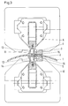
- Figure 3 shows in the same cross section as in Figure 1, a second embodiment of the Device according to the invention, the same reference numerals for the same parts have been used.
- roller knives 11, 12 In contrast to the embodiment in FIG. 1, instead of the standing knives 7, 8 roller knives 11, 12 attached to the movable tool carrier 6, 6 '. Axes 13, 14 of the rolling knives 11, 12 are at an angle to the axis of the tool carriers 6, 6 '. By this inclination is on the side facing away from the upsetting ridge 4, 5 Generates free space, the unhindered rolling movement of the rolling knives 11, 12th ensures. Comparable to the standing knives, the rolling knives 11, 12 have Cutting area a wedge-shaped cross section. To support the side The jaws 2, 3 cut into the cutting ridge 4, 5 facing side each have a nose 15, 16, which is wedge-shaped in cross section are.
Landscapes
- Physics & Mathematics (AREA)
- Optics & Photonics (AREA)
- Engineering & Computer Science (AREA)
- Mechanical Engineering (AREA)
- Milling, Broaching, Filing, Reaming, And Others (AREA)
- Pressure Welding/Diffusion-Bonding (AREA)
- Shearing Machines (AREA)
Description
Es zeigen:
- Figur 1
- einen Querschnitt durch eine erste Ausführungsform der Vorrichtung
- Figur 2
- einen Schnitt A-A in Figur 1
- Figur 3
- einen Querschnitt durch eine zweite Ausführungsform.
Claims (2)
- Vorrichtung zur Beseitigung eines beim Widerstandspreßschweißen erzeugten Stauchgrates (4,5) bei der Herstellung von metallischen Felgenbandagen (1) mit mindestens einer Klemmvorrichtung (2,3) für das Werkstück und einem in Längsrichtung des Stauchgrates (4,5) verfahrbaren Werkzeugträger (6,6'), auf dem ein je oberhalb und unterhalb des Werkstückes angeordnetes spanabhebendes Werkzeug (7,8, 11,12) befestigt ist,
dadurch gekennzeichnet,
daß das Werkzeug ein Scheidmesser (7,8) ist, das in Schneidrichtung eine zur Längsrichtung schrägstehende Schneidkante (17) und senkrecht zur Längsrichtung einen keilförmigen Querschnitt aufweist, wobei das Einschneiden in den Stauchgrat (4,5) nur etwas oberhalb der umgebenden Werkstückoberfläche erfolgt. - Vorrichtung nach Anspruch 1
dadurch gekennzeichnet,
daß das Schneidmesser als Rollmesser (11,12) ausgebildet ist und die Klemmbacken (2,3) auf der Klemmseite je eine den Stauchgrat (4,5) zugewandte messerförmige Nase (15,16) aufweisen.
Applications Claiming Priority (2)
| Application Number | Priority Date | Filing Date | Title |
|---|---|---|---|
| DE19535574 | 1995-09-14 | ||
| DE19535574A DE19535574C1 (de) | 1995-09-14 | 1995-09-14 | Verfahren und Vorrichtung zur Beseitigung eines Stauchgrates |
Publications (2)
| Publication Number | Publication Date |
|---|---|
| EP0763398A1 EP0763398A1 (de) | 1997-03-19 |
| EP0763398B1 true EP0763398B1 (de) | 1998-11-18 |
Family
ID=7773100
Family Applications (1)
| Application Number | Title | Priority Date | Filing Date |
|---|---|---|---|
| EP96250177A Expired - Lifetime EP0763398B1 (de) | 1995-09-14 | 1996-08-15 | Verfahren und Vorrichtung zur Beseitigung eines Stauchgrates |
Country Status (4)
| Country | Link |
|---|---|
| US (1) | US5806395A (de) |
| EP (1) | EP0763398B1 (de) |
| CZ (1) | CZ290940B6 (de) |
| DE (2) | DE19535574C1 (de) |
Families Citing this family (8)
| Publication number | Priority date | Publication date | Assignee | Title |
|---|---|---|---|---|
| DE102006002182A1 (de) * | 2006-01-16 | 2007-07-26 | J. Eberspächer GmbH & Co. KG | Verfahren und Vorrichtung zum Entfernen eines Körpers aus einem Gehäuse |
| JP5267509B2 (ja) * | 2010-06-17 | 2013-08-21 | 日産自動車株式会社 | 切断装置及び切断方法 |
| CN102837075B (zh) * | 2011-06-20 | 2014-07-02 | 泉州市泰达车轮设备有限公司 | 汽车车轮往复式刮渣机 |
| CN203768712U (zh) * | 2013-11-08 | 2014-08-13 | 株式会社瑞光 | 织物切断装置 |
| FR3015329B1 (fr) * | 2013-12-19 | 2016-05-20 | Aerolia | Procede, dispositif et systeme d'assemblage d'une pluralite de panneaux |
| CN105478916B (zh) * | 2015-12-23 | 2017-11-24 | 佛山欧亚特机械设备有限公司 | 一种五轴切割机 |
| CN110328413A (zh) * | 2019-07-12 | 2019-10-15 | 蚌埠捷顺机器有限公司 | 一种轮辋焊缝磨削装置 |
| CN116748603B (zh) * | 2023-06-28 | 2024-09-06 | 东莞市毅帆五金模具有限公司 | 散热器铸件翅片去毛刺机构 |
Family Cites Families (9)
| Publication number | Priority date | Publication date | Assignee | Title |
|---|---|---|---|---|
| DE459571C (de) * | 1928-05-08 | Fried Krupp Grusonwerk Akt Ges | Schneidstahl | |
| US2009670A (en) * | 1930-08-18 | 1935-07-30 | Henry E Morton | Flash removing machine |
| FR1458948A (fr) * | 1965-04-12 | 1966-04-29 | Lorraine Escaut Sa | Dispositif pour raboter les rives d'un feuillard |
| AU450099B2 (en) * | 1971-10-12 | 1974-06-27 | Tubemakers Of Australia Limited | Broach for machining of internal weld upset in the electric resistance weld process of pipe manufacture |
| DE3034243A1 (de) * | 1980-09-09 | 1982-04-22 | Siemens AG, 1000 Berlin und 8000 München | Verfahren und vorrichtung zum stumpfen kaltpressschweissen von draehten oder baendern |
| US4562326A (en) * | 1984-03-27 | 1985-12-31 | Grotnes Metalforming Systems, Inc. | Machine for welding automotive wheel rim blanks |
| FR2608481A1 (fr) * | 1986-12-17 | 1988-06-24 | Miniscloux Francis | Dispositif de rabotage a deplacement circulaire, continu ou non, du bourrelet de soudure des tubes soudes en continu |
| US5007318A (en) * | 1989-12-20 | 1991-04-16 | National Steel Corporation | Metal strip edge trimming apparatus |
| US5192013A (en) * | 1991-09-20 | 1993-03-09 | Abbey Etna Machine Company | Scarfing apparatus |
-
1995
- 1995-09-14 DE DE19535574A patent/DE19535574C1/de not_active Expired - Fee Related
-
1996
- 1996-08-15 DE DE59600829T patent/DE59600829D1/de not_active Expired - Fee Related
- 1996-08-15 EP EP96250177A patent/EP0763398B1/de not_active Expired - Lifetime
- 1996-09-13 US US08/716,640 patent/US5806395A/en not_active Expired - Fee Related
- 1996-09-13 CZ CZ19962692A patent/CZ290940B6/cs not_active IP Right Cessation
Also Published As
| Publication number | Publication date |
|---|---|
| CZ269296A3 (en) | 1997-04-16 |
| DE19535574C1 (de) | 1996-10-24 |
| EP0763398A1 (de) | 1997-03-19 |
| CZ290940B6 (cs) | 2002-11-13 |
| DE59600829D1 (de) | 1998-12-24 |
| US5806395A (en) | 1998-09-15 |
Similar Documents
| Publication | Publication Date | Title |
|---|---|---|
| DE19911927B4 (de) | Formfräser und Verfahren zur Formung einer Nut unter Verwendung desselben | |
| DE2811567C3 (de) | Bohrschraube sowie Verfahren und Vorrichtung zu ihrer Herstellung | |
| DE19654584B4 (de) | Käfig für Nadellager und Verfahren zu dessen Herstellung | |
| EP0623417A2 (de) | Stanzblech, Verfahren zu seiner Herstellung und Werkzeug zur Durchführung des Verfahrens | |
| DE19535574C1 (de) | Verfahren und Vorrichtung zur Beseitigung eines Stauchgrates | |
| DE2520346A1 (de) | Rotationsstanzwerkzeug und verfahren zu seiner herstellung | |
| DE102004022360B4 (de) | Verfahren zur Feinbearbeitung, vorzugsweise zur Feinstschlichtbearbeitung, von Werkstücken vorzugsweise von Kurbelwellen | |
| DE19854481C2 (de) | Verfahren und Vorrichtung zum Drückwalzen | |
| DE3119533C2 (de) | Maschinen zum Läppen der Kanten zwischen der Außen- und/oder Innenumfangsfläche und den Schnittflächen von an einer Stelle ihres Umfanges einen axial verlaufenden Schlitz aufweisenden ringförmigen Werkstücke | |
| EP1518631B1 (de) | Verfahren zur Formgebung und/oder zum mechanischen Entfernen von Ablagerungen, insbesondere von Ablagerungen an Schweisselektroden für das Widerstandsschweissen | |
| EP3269505A1 (de) | Bearbeitungswerkzeug, insbesondere rollierwerkzeug, sowie verfahren zum bearbeiten einer zylinderlauffläche | |
| DE19855364A1 (de) | Schneidenteil mit profilierten Schneiden zum Trennen und Formatieren | |
| EP0221510A2 (de) | Verfahren und Vorrichtung zur Bearbeitung der Laufflächen von Eisenbahnschienen durch Fräsen | |
| EP2523775B1 (de) | Verfahren zur bearbeitung von stangen- oder rohrmaterial oder einlegeteilen zur herstellung von rotationssymmetrischen werkstücken | |
| EP0841116A2 (de) | Verfahren zum Bearbeiten von rotationssymmetrischen Werkstückflächen sowie Werkzeug zur Durchführung eines solchen Verfahrens | |
| DE4130927C2 (de) | Werkzeugzahnrad zum Entgraten bzw. Anfasen der Stirnkanten der Zähne eines schrägverzahnten Werkstückzahnrades | |
| DE10227574A1 (de) | Verfahren zur Herstellung einer Felge und Felge, insbesondere für ein Fahrrad | |
| EP3875197B1 (de) | Verfahren zum abtrennen von rohrstücken | |
| DE112011103571T5 (de) | Schneideinsatz mit abgewinkelter Schneidkante, Schneidwerkzeug und Verfahren | |
| DE102018211380A1 (de) | Vorrichtung und Verfahren zum Abtrennen von stabförmigen Segmenten der Tabak verarbeitenden Industrie von einem Strang | |
| EP4385694A1 (de) | Verfahren zur instandsetzung eines zerspannungswerkzeugs | |
| EP1433577B1 (de) | Werkzeug zum Durchtrennen von Rohren | |
| DD200558A1 (de) | Verfahren und vorrichtung zum herstellen von schraubendruckfedern | |
| DE2348127C3 (de) | Vorrichtung zum Ablängen, Stauchen und Planschleifen von zylindrischen Schraubendruckfedern | |
| DE29615506U1 (de) | Messer zum Einsatz in eine Bearbeitungsvorrichtung von Kunststoffteilen sowie Vorrichtung mit einem derartigen Messer |
Legal Events
| Date | Code | Title | Description |
|---|---|---|---|
| PUAI | Public reference made under article 153(3) epc to a published international application that has entered the european phase |
Free format text: ORIGINAL CODE: 0009012 |
|
| AK | Designated contracting states |
Kind code of ref document: A1 Designated state(s): CH DE FR GB IT LI |
|
| 17P | Request for examination filed |
Effective date: 19970121 |
|
| 17Q | First examination report despatched |
Effective date: 19970716 |
|
| GRAG | Despatch of communication of intention to grant |
Free format text: ORIGINAL CODE: EPIDOS AGRA |
|
| GRAG | Despatch of communication of intention to grant |
Free format text: ORIGINAL CODE: EPIDOS AGRA |
|
| GRAH | Despatch of communication of intention to grant a patent |
Free format text: ORIGINAL CODE: EPIDOS IGRA |
|
| GRAH | Despatch of communication of intention to grant a patent |
Free format text: ORIGINAL CODE: EPIDOS IGRA |
|
| GRAA | (expected) grant |
Free format text: ORIGINAL CODE: 0009210 |
|
| AK | Designated contracting states |
Kind code of ref document: B1 Designated state(s): CH DE FR GB IT LI |
|
| REG | Reference to a national code |
Ref country code: CH Ref legal event code: NV Representative=s name: E. BLUM & CO. PATENTANWAELTE Ref country code: CH Ref legal event code: EP |
|
| ET | Fr: translation filed | ||
| REF | Corresponds to: |
Ref document number: 59600829 Country of ref document: DE Date of ref document: 19981224 |
|
| GBT | Gb: translation of ep patent filed (gb section 77(6)(a)/1977) |
Effective date: 19990217 |
|
| PLBE | No opposition filed within time limit |
Free format text: ORIGINAL CODE: 0009261 |
|
| STAA | Information on the status of an ep patent application or granted ep patent |
Free format text: STATUS: NO OPPOSITION FILED WITHIN TIME LIMIT |
|
| 26N | No opposition filed | ||
| REG | Reference to a national code |
Ref country code: GB Ref legal event code: IF02 |
|
| PGFP | Annual fee paid to national office [announced via postgrant information from national office to epo] |
Ref country code: DE Payment date: 20070822 Year of fee payment: 12 |
|
| REG | Reference to a national code |
Ref country code: CH Ref legal event code: PFA Owner name: MANNESMANN AKTIENGESELLSCHAFT Free format text: MANNESMANN AKTIENGESELLSCHAFT#MANNESMANNUFER 2#40213 DUESSELDORF (DE) -TRANSFER TO- MANNESMANN AKTIENGESELLSCHAFT#MANNESMANNUFER 2#40213 DUESSELDORF (DE) |
|
| PGFP | Annual fee paid to national office [announced via postgrant information from national office to epo] |
Ref country code: CH Payment date: 20070815 Year of fee payment: 12 |
|
| PGFP | Annual fee paid to national office [announced via postgrant information from national office to epo] |
Ref country code: GB Payment date: 20070823 Year of fee payment: 12 |
|
| PGFP | Annual fee paid to national office [announced via postgrant information from national office to epo] |
Ref country code: IT Payment date: 20070827 Year of fee payment: 12 |
|
| PGFP | Annual fee paid to national office [announced via postgrant information from national office to epo] |
Ref country code: FR Payment date: 20070812 Year of fee payment: 12 |
|
| REG | Reference to a national code |
Ref country code: CH Ref legal event code: PL |
|
| GBPC | Gb: european patent ceased through non-payment of renewal fee |
Effective date: 20080815 |
|
| REG | Reference to a national code |
Ref country code: FR Ref legal event code: ST Effective date: 20090430 |
|
| PG25 | Lapsed in a contracting state [announced via postgrant information from national office to epo] |
Ref country code: LI Free format text: LAPSE BECAUSE OF NON-PAYMENT OF DUE FEES Effective date: 20080831 Ref country code: CH Free format text: LAPSE BECAUSE OF NON-PAYMENT OF DUE FEES Effective date: 20080831 |
|
| PG25 | Lapsed in a contracting state [announced via postgrant information from national office to epo] |
Ref country code: IT Free format text: LAPSE BECAUSE OF NON-PAYMENT OF DUE FEES Effective date: 20080815 Ref country code: FR Free format text: LAPSE BECAUSE OF NON-PAYMENT OF DUE FEES Effective date: 20080901 Ref country code: DE Free format text: LAPSE BECAUSE OF NON-PAYMENT OF DUE FEES Effective date: 20090303 |
|
| PG25 | Lapsed in a contracting state [announced via postgrant information from national office to epo] |
Ref country code: GB Free format text: LAPSE BECAUSE OF NON-PAYMENT OF DUE FEES Effective date: 20080815 |