EP0762003A1 - Synchronising apparatus for change-speed gearing, especially for motor vehicle transmissions - Google Patents
Synchronising apparatus for change-speed gearing, especially for motor vehicle transmissions Download PDFInfo
- Publication number
- EP0762003A1 EP0762003A1 EP96112930A EP96112930A EP0762003A1 EP 0762003 A1 EP0762003 A1 EP 0762003A1 EP 96112930 A EP96112930 A EP 96112930A EP 96112930 A EP96112930 A EP 96112930A EP 0762003 A1 EP0762003 A1 EP 0762003A1
- Authority
- EP
- European Patent Office
- Prior art keywords
- teeth
- roof surfaces
- gear
- toothing
- spherical
- Prior art date
- Legal status (The legal status is an assumption and is not a legal conclusion. Google has not performed a legal analysis and makes no representation as to the accuracy of the status listed.)
- Granted
Links
Images
Classifications
-
- F—MECHANICAL ENGINEERING; LIGHTING; HEATING; WEAPONS; BLASTING
- F16—ENGINEERING ELEMENTS AND UNITS; GENERAL MEASURES FOR PRODUCING AND MAINTAINING EFFECTIVE FUNCTIONING OF MACHINES OR INSTALLATIONS; THERMAL INSULATION IN GENERAL
- F16D—COUPLINGS FOR TRANSMITTING ROTATION; CLUTCHES; BRAKES
- F16D23/00—Details of mechanically-actuated clutches not specific for one distinct type
- F16D23/02—Arrangements for synchronisation, also for power-operated clutches
- F16D23/04—Arrangements for synchronisation, also for power-operated clutches with an additional friction clutch
- F16D23/06—Arrangements for synchronisation, also for power-operated clutches with an additional friction clutch and a blocking mechanism preventing the engagement of the main clutch prior to synchronisation
- F16D2023/0656—Details of the tooth structure; Arrangements of teeth
- F16D2023/0668—Details relating to tooth end or tip geometry
Definitions
- the invention relates to a synchronizing device for clutches, in particular for manual transmissions for motor vehicles, according to the preamble of claim 1.
- the axial end faces of the teeth of the switching toothing and locking toothing are designed as sloping ceilings or wedge surfaces in order to facilitate an engagement of the teeth in axial sliding movements when tooth is accidentally on tooth.
- the wedge surfaces are designed as flat surfaces.
- the apex angles of the wedge surfaces or sloping ceilings are usually the same on all teeth, but can also be different on different teeth according to the cited document, the apex angle of elongated teeth on the gearshift sleeve preferably being smaller than that of the non-elongated teeth. Due to the different length of the teeth on the shift sleeve, the shift path can advantageously be shortened.
- the flat shape of the roof surfaces on the axial end faces of the teeth leads to edge pressure in the foot area of the locking teeth, due to the inevitable tolerances during production, which makes shifting difficult even when the gearbox is cold, even after synchronization has been achieved Parts triggers and on the other hand for the partial contact of the roof surfaces only in the head area of the locking teeth, so that the locking surface is then too small for a safe locking of the clutch in the unsynchronized state and thus the circuit tends to scratch.
- the invention has for its object to improve a synchronizing device of the type mentioned in that the defects occurring due to edge pressure on the roof surfaces or only partial contact of the roof surfaces in the head region of the locking toothing, namely stiff switching or insufficient synchronization, even when the usual manufacturing tolerances do not occur.
- the proposed measures can also be implemented at no additional cost if the synchronizing ring carries the spherical roof surfaces and is produced in the usual manner without cutting (e.g. by sintering, forging, casting).
- the tool costs can also be kept relatively low.
- Gear 2 is rotatably mounted on a shaft 1 of a manual transmission by means of needle bearings 3.
- the gear 2, formed from a wheel disc 4 and a clutch body 5, has on the outer periphery of the wheel disc 4 a toothing 6, with which it is in engagement with a counter gear, not shown, and forms a pair of gearwheels with the latter, and a switching toothing 7 and a tapered friction surface 8.
- a guide hub 9 With the shaft 1 rotatably and non-displaceably connected is a guide hub 9, on the outer circumference of which a shift sleeve 10 is rotatably but axially displaceable from a central position a in the directions of arrows b and c.
- the gearshift sleeve 10 has an internal toothing 11 which, when the gearshift sleeve 10 is moved in the direction of the arrow c engages over the gear teeth 7.
- the guide hub 9 guides a synchronizing ring 12, which is provided with a locking toothing 13 corresponding to the diameter of the switching toothing 7 and with a friction surface 14 adapted to and interacting with the friction surface 8.
- the synchronizer ring 12 can be rotated relative to the guide hub 9 or the shift sleeve 10 in both directions of rotation by the pitch of half a tooth of the locking toothing 13 and can also be axially displaced relative to the guide hub 9 and the coupling body 5.
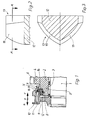
- Both the locking teeth 13 of the synchronizer ring 12 and the inner teeth 11 of the shift sleeve 10 are provided on the mutually facing end faces with roof surfaces 15 and 16, respectively.
- the roof surfaces 16 of the internal toothing 11 are formed in the usual way as flat surfaces.
- the roof surfaces 15 of the locking teeth 13, however, are designed as three-dimensional spherical surfaces. The shape of these surfaces is advantageously a spherical cutout, but can also be used as another shape, such as. B. as an ellipsoid cutout.
- the gear wheel 2 is connected to the shaft 1 in a rotationally rigid manner via the switching sleeve 10 and the guide hub 9.
- the shift sleeve 10 is shifted from the central position a in the direction of the arrow c by means of a shift fork (not shown), the synchronizing ring 12 also being carried along until it rests with its conical friction surface 14 on the likewise conical friction surface 8 of the coupling body 5.
- the internal toothing 11 of the shift sleeve 10 can slide over the locking toothing 13 of the synchronizing ring 12 without greater resistance, the punctiform contact of the curved roof surfaces 15 of the locking toothing 13 on the flat roof surfaces 16 of the Internal toothing 11 jamming or snagging safely is avoided.
- the internal toothing 11 can thus reach and engage the switching toothing 7 on the coupling body 5. This completes the switching process.
- the synchronizing ring 12 is carried along by the frictional torque on the friction surfaces 8 and 14 and rotated by half a tooth pitch of the locking teeth 13 with respect to the shift sleeve 10.
- the shift path of the shift sleeve 10 remains blocked until synchronous speeds between the shaft 1 and the gear 2 are established. Only then can the internal toothing 11 of the shift sleeve 10 with its roof surfaces 16 turn the locking toothing 13 of the synchronizing ring 12 on their spherically curved roof surfaces 15 to such an extent that the internal toothing 11 can slide over the locking toothing 13 to the switching toothing 7.
- the invention is not limited to the example described, rather it can be used with all synchronizing devices in which locking teeth with roof surfaces are used on the end face. It is also possible to provide the spherical shape of the roof surfaces on the internal toothing of the gearshift sleeve and, on the other hand, to design the roof surfaces of the locking toothing as flat surfaces.
Abstract
Description
Die Erfindung betrifft eine Synchronisiereinrichtung für Schaltkupplungen, insbesondere von Schaltgetrieben für Kraftfahrzeuge, nach dem Oberbegriff des Anspruchs 1.The invention relates to a synchronizing device for clutches, in particular for manual transmissions for motor vehicles, according to the preamble of claim 1.
Eine solche Synchronisiereinrichtung ist mit DE 26 59 448 C2 beschrieben und dargestellt. Bei dieser bekannten Ausführung sind die axialen Stirnseiten der Zähne von Schaltverzahnung und Sperrverzahnung als Dachschrägen oder Keilflächen ausgebildet, um bei axialen Schiebebewegungen ein Eingreifen der Zähne ineinander dann zu erleichtern, wenn zufällig Zahn auf Zahn steht. Die Keilflächen sind als ebene Flächen ausgebildet. Die Scheitelwinkel der Keilflächen oder Dachschrägen sind üblicherweise an allen Zähnen gleich, können jedoch nach der genannten Druckschrift an verschiedenen Zähnen auch unterschiedlich sein, wobei bevorzugt der Scheitelwinkel verlängerter Zähne an der Schaltmuffe kleiner als der unverlängerter Zähne ist. Durch die unterschiedliche Länge der Zähne an der Schaltmuffe kann der Schaltweg vorteilhaft verkürzt werden. Die ebene Form der Dachflächen an den axialen Stirnseiten der Zähne führt jedoch infolge der unvermeidlichen Toleranzen bei der Fertigung einerseits zu Kantenpressung im Fußbereich der Sperrverzahnung, was besonders bei kaltem Getriebe schwergängiges Schalten auch nach Erreichen von Gleichlauf der zu schaltenden Teile auslöst und andererseits zur partiellen Anlage der Dachflächen nur im Kopfbereich der Sperrverzahnung, so daß dann die Sperrfläche zu klein ist für eine sichere Sperrung der Schaltkupplung im unsynchronisierten Zustand und damit die Schaltung zum Kratzen neigt.Such a synchronizing device is described and illustrated with DE 26 59 448 C2. In this known embodiment, the axial end faces of the teeth of the switching toothing and locking toothing are designed as sloping ceilings or wedge surfaces in order to facilitate an engagement of the teeth in axial sliding movements when tooth is accidentally on tooth. The wedge surfaces are designed as flat surfaces. The apex angles of the wedge surfaces or sloping ceilings are usually the same on all teeth, but can also be different on different teeth according to the cited document, the apex angle of elongated teeth on the gearshift sleeve preferably being smaller than that of the non-elongated teeth. Due to the different length of the teeth on the shift sleeve, the shift path can advantageously be shortened. However, the flat shape of the roof surfaces on the axial end faces of the teeth, on the one hand, leads to edge pressure in the foot area of the locking teeth, due to the inevitable tolerances during production, which makes shifting difficult even when the gearbox is cold, even after synchronization has been achieved Parts triggers and on the other hand for the partial contact of the roof surfaces only in the head area of the locking teeth, so that the locking surface is then too small for a safe locking of the clutch in the unsynchronized state and thus the circuit tends to scratch.
Das Schaltverhalten einer solchen Synchronisiereinrichtung zu verbessern, insbesondere eine selbsttätige Axialbewegung der Schaltmuffe zu verhindern, wird mit DE 37 14 190 C2 vorgeschlagen, im Bereich vertiefter Zahnnuten der Schaltmuffe glatte Seitenflanken vorzusehen, die in entsprechend höhere Zähne des Synchronringes führend eingreifen. Ein Hinweis auf das Vermeiden von Kantenpressung und reduziertes Synchronisiervermögen wird jedoch nicht gegeben.DE 37 14 190 C2 proposes to improve the switching behavior of such a synchronizing device, in particular to prevent an automatic axial movement of the shift sleeve, to provide smooth side flanks in the area of recessed tooth grooves of the shift sleeve which engage in correspondingly higher teeth of the synchronizer ring. However, there is no indication of avoiding edge pressure and reduced synchronizing ability.
Der Erfindung liegt die Aufgabe zugrunde, eine Synchronisiereinrichtung der eingangs genannten Art dahingehend zu verbessern, daß die infolge Kantenpressung an den Dachflächen bzw. nur teilweise Anlage der Dachflächen im Kopfbereich der Sperrverzahnung auftretenden Mängel, nämlich schwergängiges Schalten bzw. unzureichendes Synchronisieren, auch bei Vorliegen der üblichen Fertigungstoleranzen nicht auftreten.The invention has for its object to improve a synchronizing device of the type mentioned in that the defects occurring due to edge pressure on the roof surfaces or only partial contact of the roof surfaces in the head region of the locking toothing, namely stiff switching or insufficient synchronization, even when the usual manufacturing tolerances do not occur.
Erfindungsgemäß wird diese Aufgabe durch die kennzeichnenden Merkmale des Anspruches 1 gelöst.According to the invention, this object is achieved by the characterizing features of claim 1.
Infolge der Balligkeit der einen, z. B. auf dem Synchronring befindlichen, Dachfläche, liegt deren Berührungspunkt auch bei den toleranzbedingten maßlichen Abweichungen immer in einem definierten mittleren Bereich der ebenen Dachfläche, z. B. der der Innenverzahnung der Schaltmuffe.Due to the crowning of one, e.g. B. located on the synchronizer ring, roof surface, their point of contact is always in a defined central area of the flat roof surface, z. B. the internal toothing of the shift sleeve.
Ein Durchschalten ist somit ohne Kraftsteigerung und Zeitverzug möglich. Es ergibt sich für alle praktischen Toleranzfälle die vorgesehene Sperrsicherheit.Switching through is therefore possible without increasing power and delay. It results for all practical Tolerance cases the intended locking security.
Die vorgeschlagenen Maßnahmen sind darüber hinaus ohne zusätzliche Kosten realisierbar, wenn der Synchronisierring die balligen Dachflächen trägt und in üblicher Weise spanlos (z. B. durch Sintern, Schmieden, Gießen) hergestellt wird.The proposed measures can also be implemented at no additional cost if the synchronizing ring carries the spherical roof surfaces and is produced in the usual manner without cutting (e.g. by sintering, forging, casting).
Bei Ausführung der balligen Flächen als Kugelfläche können auch die Werkzeugkosten relativ gering gehalten werden.When the spherical surfaces are designed as spherical surfaces, the tool costs can also be kept relatively low.
Ein Ausführungsbeispiel der Erfindung ist nachstehend anhand einer Zeichnung näher beschrieben. Es zeigen
- Fig. 1:
- einen Schnitt durch eine Synchronisiereinrichtung;
- Fig. 2:
- eine Einzelheit bei X in Figur 1 in vergrößertem Maßstab;
- Fig. 3:
- einen Schnitt entlang der Linie A-A in
Figur 2.
- Fig. 1:
- a section through a synchronizer;
- Fig. 2:
- a detail at X in Figure 1 on an enlarged scale;
- Fig. 3:
- a section along the line AA in Figure 2.
Auf einer Welle 1 eines Schaltgetriebes ist Zahnrad 2 mittels Nadellager 3 drehbar gelagert. Das Zahnrad 2, gebildet aus einer Radscheibe 4 und einem Kupplungskörper 5, hat am äußeren Umfang der Radscheibe 4 eine Verzahnung 6, mit welcher es in Eingriff mit einem nicht dargestellten Gegenzahnrad steht und mit diesem ein Zahnradpaar bildet sowie am Kupplungskörper 5 eine Schaltverzahnung 7 und eine keglige Reibfläche 8. Mit der Welle 1 drehfest und unverschiebbar verbunden ist eine Führungsnabe 9, auf deren äußeren Umfang eine Schaltmuffe 10 unverdrehbar, aber axial aus einer Mittellage a verschiebbar in die Richtungen der Pfeile b und c gelagert ist. Die Schaltmuffe 10 hat eine Innenverzahnung 11, welche beim Verschieben der Schaltmuffe 10 in Richtung des Pfeiles c über die Schaltverzahnung 7 greift. Die Führungsnabe 9 führt einen Synchronisierring 12, der mit einer dem Durchmesser der Schaltverzahnung 7 entsprechenden Sperrverzahnung 13 und einer der Reibfläche 8 angepaßten und mit ihr zusammenwirkenden Reibfläche 14 versehen ist.Gear 2 is rotatably mounted on a shaft 1 of a manual transmission by means of
Der Synchronring 12 ist gegenüber der Führungsnabe 9 bzw. der Schaltmuffe 10 in beiden Drehrichtungen um die Teilung eines halben Zahnes der Sperrverzahnung 13 verdrehbar und im übrigen gegenüber der Führungsnabe 9 und dem Kupplungskörper 5 axial verschiebbar. Sowohl die Sperrverzahnung 13 des Synchronringes 12 als auch die Innenverzahnung 11 der Schaltmuffe 10 sind an den aneinander zugekehrten Stirnseiten mit Dachflächen 15 bzw. 16 versehen. Die Dachflächen 16 der Innenverzahnung 11 sind in üblicher Weise als ebene Flächen ausgebildet. Die Dachflächen 15 der Sperrverzahnung 13 dagegen sind als dreidimensional ballige Flächen gestaltet. Die Form dieser Flächen ist vorteilhaft ein Kugelausschnitt, kann jedoch auch als andere Form, wie z. B. als Ellipsoidausschnitt, gebildet sein.The
Beim Schaltvorgang wird das Zahnrad 2 über die Schaltmuffe 10 und die Führungsnabe 9 drehstarr mit der Welle 1 verbunden. Dazu wird die Schaltmuffe 10 mittels einer nicht dargestellten Schaltgabel aus der Mittelstellung a in Richtung des Pfeiles c verschoben, wobei auch der Synchronisierring 12 solange mitgenommen wird, bis er mit seiner konischen Reibfläche 14 an der gleichfalls konischen Reibfläche 8 des Kupplungskörpers 5 anliegt. Besteht zwischen der Welle 1 und dem Zahnrad 2 keine Drehzahldifferenz, dann kann die Innenverzahnung 11 der Schaltmuffe 10 ohne größeren Widerstand über die Sperrverzahnung 13 des Synchronisierringes 12 gleiten, wobei durch die punktuelle Anlage der gewölbten Dachflächen 15 der Sperrverzahnung 13 an den ebenen Dachflächen 16 der Innenverzahnung 11 ein Verkanten oder Verhaken sicher vermieden wird. Die Innenverzahnung 11 kann so die Schaltverzahnung 7 am Kupplungskörper 5 erreichen und in diese eingreifen. Damit ist der Schaltvorgang beendet.During the switching process, the
Besteht zwischen der Welle 1 und dem Zahnrad 2 eine Drehzahldifferenz, dann wird der Synchronisierring 12 durch das Reibmoment an den Reibflächen 8 und 14 mitgenommen und um eine halbe Zahnteilung der Sperrverzahnung 13 gegenüber der Schaltmuffe 10 verdreht. Der Schaltweg bleibt der Schaltmuffe 10 somit solange versperrt, bis synchrone Drehzahlen zwischen der Welle 1 und dem Zahnrad 2 hergestellt sind. Erst dann kann die Innenverzahnung 11 der Schaltmuffe 10 mit ihren Dachflächen 16 die Sperrverzahnung 13 des Synchronisierringes 12 an deren sphärisch gewölbten Dachflächen 15 so weit verdrehen, daß die Innenverzahnung 11 über die Sperrverzahnung 13 zu der Schaltverzahnung 7 gleiten kann. Durch die dreidimensionale ballige Form der Dachflächen 15 wird auch bei relativ großen Fertigungstoleranzen eine Berührungszone zwischen den Dachflächen 15 und den Dachflächen 16 der Innenverzahnung 11 eingehalten, die mit sehr guter Annäherung der theoretischen Berührungszone in Mitte der Dachflächen 15, 16 entspricht. Die Synchronisation erfolgt somit in gewünschtem Maße, und ein Verhaken der Schaltung tritt nicht ein.If there is a speed difference between the shaft 1 and the
Die Erfindung ist nicht auf das beschriebene Beispiel beschränkt, sie ist vielmehr bei allen Synchronisiereinrichtungen anwendbar, bei denen eine Sperrverzahnung mit Dachflächen an der Stirnseite Verwendung findet. Dabei ist es auch möglich, die ballige Form der Dachflächen an der Innenverzahnung der Schaltmuffe vorzusehen und die Dachflächen der Sperrverzahnung dagegen als ebene Flächen auszubilden.The invention is not limited to the example described, rather it can be used with all synchronizing devices in which locking teeth with roof surfaces are used on the end face. It is also possible to provide the spherical shape of the roof surfaces on the internal toothing of the gearshift sleeve and, on the other hand, to design the roof surfaces of the locking toothing as flat surfaces.
Claims (5)
Applications Claiming Priority (2)
| Application Number | Priority Date | Filing Date | Title |
|---|---|---|---|
| DE19531155A DE19531155A1 (en) | 1995-08-24 | 1995-08-24 | Synchronizing device for clutches, in particular of manual transmissions for motor vehicles |
| DE19531155 | 1995-08-24 |
Publications (2)
| Publication Number | Publication Date |
|---|---|
| EP0762003A1 true EP0762003A1 (en) | 1997-03-12 |
| EP0762003B1 EP0762003B1 (en) | 1999-10-27 |
Family
ID=7770282
Family Applications (1)
| Application Number | Title | Priority Date | Filing Date |
|---|---|---|---|
| EP96112930A Expired - Lifetime EP0762003B1 (en) | 1995-08-24 | 1996-08-12 | Synchronising apparatus for change-speed gearing, especially for motor vehicle transmissions |
Country Status (4)
| Country | Link |
|---|---|
| EP (1) | EP0762003B1 (en) |
| AT (1) | ATE186105T1 (en) |
| DE (2) | DE19531155A1 (en) |
| ES (1) | ES2139290T3 (en) |
Cited By (4)
| Publication number | Priority date | Publication date | Assignee | Title |
|---|---|---|---|---|
| US6370979B1 (en) * | 1997-09-20 | 2002-04-16 | Blw Praezisionsschmiede Gmbh | Clutch gearing especially for a manual transmission |
| US10024468B2 (en) | 2014-05-09 | 2018-07-17 | Swagelok Company | Conduit fitting with components adapted for facilitating assembly |
| US10215315B2 (en) | 2008-09-05 | 2019-02-26 | Parker-Hannifin Corporation | Tube compression fitting and flared fitting used with connection body and method of making same |
| US10584814B2 (en) | 2016-03-23 | 2020-03-10 | Swagelok Company | Conduit fitting with stroke resisting features |
Families Citing this family (2)
| Publication number | Priority date | Publication date | Assignee | Title |
|---|---|---|---|---|
| DE102006050503A1 (en) * | 2006-10-26 | 2008-04-30 | GM Global Technology Operations, Inc., Detroit | Shifting clutch for switching device or synchronizing device, particularly control gear of vehicle, has ratchet wheel provided with selector teeth and pivoted on shaft around axis |
| DE102009027719B4 (en) * | 2009-07-15 | 2018-08-09 | Zf Friedrichshafen Ag | clutch |
Citations (3)
| Publication number | Priority date | Publication date | Assignee | Title |
|---|---|---|---|---|
| US2627955A (en) * | 1951-01-12 | 1953-02-10 | Fuller Mfg Co | Self-energizing means for interengaging synchronizer friction plates |
| DE1080413B (en) * | 1956-09-20 | 1960-04-21 | Daimler Benz Ag | Frictional clutch, especially for motor vehicle gearboxes |
| AU7781475A (en) * | 1974-02-04 | 1976-08-05 | Kiddle G W | Gear reclaim |
-
1995
- 1995-08-24 DE DE19531155A patent/DE19531155A1/en not_active Withdrawn
-
1996
- 1996-08-12 EP EP96112930A patent/EP0762003B1/en not_active Expired - Lifetime
- 1996-08-12 ES ES96112930T patent/ES2139290T3/en not_active Expired - Lifetime
- 1996-08-12 DE DE59603469T patent/DE59603469D1/en not_active Expired - Lifetime
- 1996-08-12 AT AT96112930T patent/ATE186105T1/en active
Patent Citations (3)
| Publication number | Priority date | Publication date | Assignee | Title |
|---|---|---|---|---|
| US2627955A (en) * | 1951-01-12 | 1953-02-10 | Fuller Mfg Co | Self-energizing means for interengaging synchronizer friction plates |
| DE1080413B (en) * | 1956-09-20 | 1960-04-21 | Daimler Benz Ag | Frictional clutch, especially for motor vehicle gearboxes |
| AU7781475A (en) * | 1974-02-04 | 1976-08-05 | Kiddle G W | Gear reclaim |
Cited By (6)
| Publication number | Priority date | Publication date | Assignee | Title |
|---|---|---|---|---|
| US6370979B1 (en) * | 1997-09-20 | 2002-04-16 | Blw Praezisionsschmiede Gmbh | Clutch gearing especially for a manual transmission |
| US10215315B2 (en) | 2008-09-05 | 2019-02-26 | Parker-Hannifin Corporation | Tube compression fitting and flared fitting used with connection body and method of making same |
| US10024468B2 (en) | 2014-05-09 | 2018-07-17 | Swagelok Company | Conduit fitting with components adapted for facilitating assembly |
| US11079046B2 (en) | 2014-05-09 | 2021-08-03 | Swagelok Company | Conduit fitting with components adapted for facilitating assembly |
| US10584814B2 (en) | 2016-03-23 | 2020-03-10 | Swagelok Company | Conduit fitting with stroke resisting features |
| US11009158B2 (en) | 2016-03-23 | 2021-05-18 | Swagelok Company | Conduit fitting with stroke resisting features |
Also Published As
| Publication number | Publication date |
|---|---|
| EP0762003B1 (en) | 1999-10-27 |
| DE59603469D1 (en) | 1999-12-02 |
| DE19531155A1 (en) | 1997-02-27 |
| ES2139290T3 (en) | 2000-02-01 |
| ATE186105T1 (en) | 1999-11-15 |
Similar Documents
| Publication | Publication Date | Title |
|---|---|---|
| DE3622464C1 (en) | ||
| EP0184077B1 (en) | Synchronising device for clutches | |
| EP0157908B1 (en) | Synchronizing device for shift clutches | |
| DE3445519C2 (en) | ||
| DE1425835B1 (en) | For gear change transmissions, especially in motor vehicles, specific lock-synchronized tooth clutch | |
| DE2751699B2 (en) | Device for noiseless switching of a reverse gear of speed change gears, in particular of motor vehicles | |
| DE3421473A1 (en) | GEARBOX SYNCHRONIZING DEVICE | |
| DE19734492A1 (en) | Coupling tooth of a gearshift sleeve of a gear coupling for coupling a gear to its shaft | |
| EP3354922B1 (en) | Synchronizing device and synchronization method | |
| EP1788271B1 (en) | Synchronizer | |
| EP0762003B1 (en) | Synchronising apparatus for change-speed gearing, especially for motor vehicle transmissions | |
| EP1693589A1 (en) | Synchromesh for a gearbox, particularly of a motor vehicule | |
| DE3729818C2 (en) | ||
| DE102012214430A1 (en) | Shifting device for auxiliary transmission in powertrain, has driver designed as cam such that rotating movement of drum switch is convertible into axial displacement of shift element, where switch comprises guiding groove | |
| EP1101965B1 (en) | Multiple synchronizer assembly for motor vehicle gear box. | |
| DE3225201A1 (en) | Synchroniser | |
| WO2001086163A1 (en) | Synchronizing device with asymmetrical toothing | |
| DE102012216419A1 (en) | Coupling element of synchronization unit in gearbox of motor car, has clutch gearing that is provided with teeth whose end surface is rounded, where teeth of clutch gearing on tooth surface are formed with undercut portion | |
| AT520443B1 (en) | Transmission synchronization device | |
| DE3803845A1 (en) | Dog clutch in a step-change gearbox | |
| DE102005002480B4 (en) | Synchronization device for a manual transmission of a motor vehicle | |
| DE2324860B2 (en) | Synchromesh baulk ring engagement face - has two planes with relatively steep and shallow angles | |
| DE4211769A1 (en) | Synchroniser clutch, for vehicle gear shift mechanism - has inner toothed sleeve, coupling with outer teeth, synchroniser ring and meshing piece | |
| DE10113948A1 (en) | Synchronization device for motor vehicle gear box has synchronization ring turnable relative to transmission shaft or synchronization body, through two different angles for different turning directions | |
| DE2222077A1 (en) | MANUAL TRANSMISSION, ESPECIALLY FOR MOTOR VEHICLES |
Legal Events
| Date | Code | Title | Description |
|---|---|---|---|
| PUAI | Public reference made under article 153(3) epc to a published international application that has entered the european phase |
Free format text: ORIGINAL CODE: 0009012 |
|
| AK | Designated contracting states |
Kind code of ref document: A1 Designated state(s): AT DE ES FR GB IT |
|
| 17P | Request for examination filed |
Effective date: 19970712 |
|
| GRAG | Despatch of communication of intention to grant |
Free format text: ORIGINAL CODE: EPIDOS AGRA |
|
| GRAG | Despatch of communication of intention to grant |
Free format text: ORIGINAL CODE: EPIDOS AGRA |
|
| GRAH | Despatch of communication of intention to grant a patent |
Free format text: ORIGINAL CODE: EPIDOS IGRA |
|
| 17Q | First examination report despatched |
Effective date: 19990316 |
|
| GRAH | Despatch of communication of intention to grant a patent |
Free format text: ORIGINAL CODE: EPIDOS IGRA |
|
| GRAA | (expected) grant |
Free format text: ORIGINAL CODE: 0009210 |
|
| ITF | It: translation for a ep patent filed |
Owner name: BARZANO' E ZANARDO ROMA S.P.A. |
|
| AK | Designated contracting states |
Kind code of ref document: B1 Designated state(s): AT DE ES FR GB IT |
|
| REF | Corresponds to: |
Ref document number: 186105 Country of ref document: AT Date of ref document: 19991115 Kind code of ref document: T |
|
| REF | Corresponds to: |
Ref document number: 59603469 Country of ref document: DE Date of ref document: 19991202 |
|
| ET | Fr: translation filed | ||
| GBT | Gb: translation of ep patent filed (gb section 77(6)(a)/1977) |
Effective date: 19991217 |
|
| REG | Reference to a national code |
Ref country code: ES Ref legal event code: FG2A Ref document number: 2139290 Country of ref document: ES Kind code of ref document: T3 |
|
| PLBE | No opposition filed within time limit |
Free format text: ORIGINAL CODE: 0009261 |
|
| STAA | Information on the status of an ep patent application or granted ep patent |
Free format text: STATUS: NO OPPOSITION FILED WITHIN TIME LIMIT |
|
| 26N | No opposition filed | ||
| REG | Reference to a national code |
Ref country code: GB Ref legal event code: IF02 |
|
| REG | Reference to a national code |
Ref country code: GB Ref legal event code: 732E Free format text: REGISTERED BETWEEN 20090219 AND 20090225 |
|
| REG | Reference to a national code |
Ref country code: GB Ref legal event code: 732E Free format text: REGISTERED BETWEEN 20090305 AND 20090311 |
|
| REG | Reference to a national code |
Ref country code: GB Ref legal event code: 732E Free format text: REGISTERED BETWEEN 20091029 AND 20091104 |
|
| REG | Reference to a national code |
Ref country code: GB Ref legal event code: 732E Free format text: REGISTERED BETWEEN 20091105 AND 20091111 |
|
| REG | Reference to a national code |
Ref country code: DE Ref legal event code: R081 Ref document number: 59603469 Country of ref document: DE Owner name: GM GLOBAL TECHNOLOGY OPERATIONS LLC (N. D. GES, US Free format text: FORMER OWNER: GM GLOBAL TECHNOLOGY OPERATIONS, INC., DETROIT, MICH., US Effective date: 20110323 Ref country code: DE Ref legal event code: R081 Ref document number: 59603469 Country of ref document: DE Owner name: GM GLOBAL TECHNOLOGY OPERATIONS LLC (N. D. GES, US Free format text: FORMER OWNER: GM GLOBAL TECHNOLOGY OPERATIONS, INC., DETROIT, US Effective date: 20110323 |
|
| PGFP | Annual fee paid to national office [announced via postgrant information from national office to epo] |
Ref country code: GB Payment date: 20120808 Year of fee payment: 17 |
|
| PGFP | Annual fee paid to national office [announced via postgrant information from national office to epo] |
Ref country code: FR Payment date: 20120823 Year of fee payment: 17 Ref country code: IT Payment date: 20120809 Year of fee payment: 17 Ref country code: DE Payment date: 20120808 Year of fee payment: 17 Ref country code: ES Payment date: 20120907 Year of fee payment: 17 |
|
| PGFP | Annual fee paid to national office [announced via postgrant information from national office to epo] |
Ref country code: AT Payment date: 20120726 Year of fee payment: 17 |
|
| REG | Reference to a national code |
Ref country code: AT Ref legal event code: MM01 Ref document number: 186105 Country of ref document: AT Kind code of ref document: T Effective date: 20130812 |
|
| GBPC | Gb: european patent ceased through non-payment of renewal fee |
Effective date: 20130812 |
|
| PG25 | Lapsed in a contracting state [announced via postgrant information from national office to epo] |
Ref country code: DE Free format text: LAPSE BECAUSE OF NON-PAYMENT OF DUE FEES Effective date: 20140301 |
|
| REG | Reference to a national code |
Ref country code: DE Ref legal event code: R119 Ref document number: 59603469 Country of ref document: DE Effective date: 20140301 |
|
| REG | Reference to a national code |
Ref country code: FR Ref legal event code: ST Effective date: 20140430 |
|
| PG25 | Lapsed in a contracting state [announced via postgrant information from national office to epo] |
Ref country code: AT Free format text: LAPSE BECAUSE OF NON-PAYMENT OF DUE FEES Effective date: 20130812 Ref country code: IT Free format text: LAPSE BECAUSE OF NON-PAYMENT OF DUE FEES Effective date: 20130812 |
|
| PG25 | Lapsed in a contracting state [announced via postgrant information from national office to epo] |
Ref country code: GB Free format text: LAPSE BECAUSE OF NON-PAYMENT OF DUE FEES Effective date: 20130812 |
|
| PG25 | Lapsed in a contracting state [announced via postgrant information from national office to epo] |
Ref country code: FR Free format text: LAPSE BECAUSE OF NON-PAYMENT OF DUE FEES Effective date: 20130902 |
|
| REG | Reference to a national code |
Ref country code: ES Ref legal event code: FD2A Effective date: 20140908 |
|
| PG25 | Lapsed in a contracting state [announced via postgrant information from national office to epo] |
Ref country code: ES Free format text: LAPSE BECAUSE OF NON-PAYMENT OF DUE FEES Effective date: 20130813 |