EP0761891A1 - Sicherheitsvorrichtung zum Einschalten zwischen eine Trinkwasserleitung und die Anschlussleitung eines Verbrauchergerätes - Google Patents
Sicherheitsvorrichtung zum Einschalten zwischen eine Trinkwasserleitung und die Anschlussleitung eines Verbrauchergerätes Download PDFInfo
- Publication number
- EP0761891A1 EP0761891A1 EP96490032A EP96490032A EP0761891A1 EP 0761891 A1 EP0761891 A1 EP 0761891A1 EP 96490032 A EP96490032 A EP 96490032A EP 96490032 A EP96490032 A EP 96490032A EP 0761891 A1 EP0761891 A1 EP 0761891A1
- Authority
- EP
- European Patent Office
- Prior art keywords
- backflow preventer
- valve
- safety
- safety valve
- sleeve
- Prior art date
- Legal status (The legal status is an assumption and is not a legal conclusion. Google has not performed a legal analysis and makes no representation as to the accuracy of the status listed.)
- Withdrawn
Links
- 239000003651 drinking water Substances 0.000 title claims description 11
- 235000020188 drinking water Nutrition 0.000 title claims description 11
- 238000010438 heat treatment Methods 0.000 claims abstract description 11
- 238000011144 upstream manufacturing Methods 0.000 claims description 24
- 239000012530 fluid Substances 0.000 claims description 7
- XLYOFNOQVPJJNP-UHFFFAOYSA-N water Substances O XLYOFNOQVPJJNP-UHFFFAOYSA-N 0.000 claims description 7
- 239000002351 wastewater Substances 0.000 claims description 2
- 238000006073 displacement reaction Methods 0.000 claims 1
- 238000009434 installation Methods 0.000 description 13
- 238000002955 isolation Methods 0.000 description 6
- 238000012423 maintenance Methods 0.000 description 3
- 239000008236 heating water Substances 0.000 description 2
- 208000031968 Cadaver Diseases 0.000 description 1
- 101100536354 Drosophila melanogaster tant gene Proteins 0.000 description 1
- 230000000295 complement effect Effects 0.000 description 1
- 238000001704 evaporation Methods 0.000 description 1
- 230000008020 evaporation Effects 0.000 description 1
- 238000010926 purge Methods 0.000 description 1
- 238000007789 sealing Methods 0.000 description 1
Images

Classifications
-
- E—FIXED CONSTRUCTIONS
- E03—WATER SUPPLY; SEWERAGE
- E03C—DOMESTIC PLUMBING INSTALLATIONS FOR FRESH WATER OR WASTE WATER; SINKS
- E03C1/00—Domestic plumbing installations for fresh water or waste water; Sinks
- E03C1/02—Plumbing installations for fresh water
- E03C1/10—Devices for preventing contamination of drinking-water pipes, e.g. means for aerating self-closing flushing valves
- E03C1/104—Devices for preventing contamination of drinking-water pipes, e.g. means for aerating self-closing flushing valves using a single check valve
-
- E—FIXED CONSTRUCTIONS
- E03—WATER SUPPLY; SEWERAGE
- E03C—DOMESTIC PLUMBING INSTALLATIONS FOR FRESH WATER OR WASTE WATER; SINKS
- E03C1/00—Domestic plumbing installations for fresh water or waste water; Sinks
- E03C1/02—Plumbing installations for fresh water
- E03C1/10—Devices for preventing contamination of drinking-water pipes, e.g. means for aerating self-closing flushing valves
- E03C1/106—Devices for preventing contamination of drinking-water pipes, e.g. means for aerating self-closing flushing valves using two or more check valves
Definitions
- the invention relates to a safety device intended to be inserted between the pipe of a drinking water distribution network and the supply pipe of a water user device, such as a boiler.
- Such a boiler and the network of radiators connected to it form a normally closed circuit in which the heating water can contain products which are liable to be dangerous for humans.
- this closed circuit To compensate for losses, for example following purges and / or evaporation, this closed circuit must be replenished periodically.
- the upstream and downstream sleeves each carry at their free end a fraction of a connection means with that of the corresponding upstream or downstream pipes.
- these connecting means can be of any known type, such as screw-nut systems in which sealing rings are provided.
- the most recent safety standards also require installers of appliances, for example boilers, to add to these backflow preventers at least one isolation valve and, preferably, two isolation valves, one upstream and the other downstream of the backflow preventer.
- the installer must first study each supply circuit of the appliance such as the boiler he wishes to install.
- each installer uses, for supply reasons, a particular type of valve.
- the installer may also have to use another type of tap, which, generally, it requires him to modify the surrounding pipes to take into account the size of the new valve, thus generating an unnecessary installation time and / or a risk of incorrect adjustment or reassembly.
- valves upstream and downstream of the backflow preventer increase the connections and therefore the risks of leaks and increase the installation times.
- These boilers must also be equipped with a safety valve which, when the temperature controls of the hot water circuit are faulty, evacuates a certain amount of water when the pressure inside the hot water circuit reaches a predetermined threshold.
- a device comprising an isolation valve placed upstream of an assembly comprising a non-return valve and a so-called vacuum breaker valve each mounted on a separate sleeve.
- valve is open.
- the isolating valve is only placed in the closed position to carry out maintenance on the safety elements.
- One of the results which the invention aims to obtain is a safety device of the type mentioned above which is easier to set up whether in new or existing installations and which reduces the potential for leakage inherent in the connections.
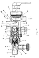
- the invention relates to such a backflow preventer in particular CHARACTERIZED in that, on the one hand, instead of the safety valve being independent of the backflow preventer, one of the sleeves of the backflow preventer directly locally the body intended to house the safety valve and, on the other hand, the discharge pipe of the backflow preventer is connected to the discharge pipe of the safety valve by an intercommunication channel itself housed in the body of the backflow preventer substantially parallel to the axis thereof, so that this safety valve is integrated into the body of the backflow preventer.
- At least one stop valve 12 is added to this backflow preventer, at least one stop valve 12 and, preferably, two stop valves, each for isolating the backflow preventer from one of the upstream and downstream pipes.
- a safety valve 20 interposed between the backflow preventer 7 and the heating circuit, which safety valve 20 also being connected to a discharge line 30.
- one of the sleeves 9, 10 of the backflow preventer produces directly locally the body intended to house the safety valve 20 and, on the other hand, the discharge pipe 8 of the backflow preventer is connected to the discharge pipe 30 of the safety valve by an intercommunication channel 31 itself housed in the body of the backflow preventer substantially parallel to the axis thereof, so that this safety valve is integrated in the body of the backflow preventer.
- the body of the safety device housing the backflow preventer and the safety valve also constitutes the body of at least one shut-off valve.
- a stop valve is provided upstream of the disconnector and / or between the disconnector and the safety valve a second stop valve.
- the stop valve placed between the backflow preventer 7 and safety valve 20 is preferably a ball valve and the valve preferably incorporates in its passage a non-return valve.
- the sleeve 10 connecting the safety device with the heating circuit is connected substantially perpendicular to the longitudinal axis of the body of the backflow preventer and the discharge pipe 30 of the safety valve 20 extends substantially parallel to the axis of this sleeve and the chamber housing the valve and this sleeve are separated at least locally by a common wall 32 which is crossed by a passage 40 having a seat for the valve shutter, the l the axis of movement is substantially parallel to the axis of the body of the backflow preventer.
- the safety valve has an operating means 60 making it possible to deliberately move the shutter away from its seat.
- the intercommunication channel extending between the shutter and the discharge pipe will have its longitudinal axis slightly inclined to promote flow.
Landscapes
- Health & Medical Sciences (AREA)
- Life Sciences & Earth Sciences (AREA)
- Engineering & Computer Science (AREA)
- Hydrology & Water Resources (AREA)
- Public Health (AREA)
- Water Supply & Treatment (AREA)
- Domestic Plumbing Installations (AREA)
- Check Valves (AREA)
Applications Claiming Priority (2)
| Application Number | Priority Date | Filing Date | Title |
|---|---|---|---|
| FR9510878 | 1995-09-12 | ||
| FR9510878A FR2738611B1 (fr) | 1995-09-12 | 1995-09-12 | Dispositif de securite destine a s'intercaler entre la conduite d'un reseau de distribution d'eau potable et la conduite d'alimentation d'un appareil utilisateur d'eau |
Publications (1)
| Publication Number | Publication Date |
|---|---|
| EP0761891A1 true EP0761891A1 (de) | 1997-03-12 |
Family
ID=9482624
Family Applications (1)
| Application Number | Title | Priority Date | Filing Date |
|---|---|---|---|
| EP96490032A Withdrawn EP0761891A1 (de) | 1995-09-12 | 1996-08-07 | Sicherheitsvorrichtung zum Einschalten zwischen eine Trinkwasserleitung und die Anschlussleitung eines Verbrauchergerätes |
Country Status (2)
| Country | Link |
|---|---|
| EP (1) | EP0761891A1 (de) |
| FR (1) | FR2738611B1 (de) |
Citations (7)
| Publication number | Priority date | Publication date | Assignee | Title |
|---|---|---|---|---|
| FR757523A (fr) * | 1932-09-27 | 1933-12-28 | Kula Freres Soc | Dispositif anti-retour d'eau |
| FR2427532A1 (fr) * | 1978-05-30 | 1979-12-28 | Watts Regulator Co | Dispositif anti-reflux |
| US4190071A (en) * | 1977-09-12 | 1980-02-26 | International Telephone And Telegraph Corporation | Backflow prevention devices |
| GB2179121A (en) * | 1985-08-17 | 1987-02-25 | Wigley Albert F | A non-return and/or anti- vacuum spring loaded valve assembly |
| FR2620785A1 (fr) * | 1987-09-22 | 1989-03-24 | Haudiquer Sa | Organe de controle de l'ecoulement d'un fluide constituant au moins un clapet anti-retour |
| DE4101114C1 (de) * | 1991-01-16 | 1992-06-04 | Gruenbeck Wasseraufbereitung Gmbh, 8884 Hoechstaedt, De | |
| EP0671515A1 (de) * | 1994-03-10 | 1995-09-13 | S.A. Haudiquer Industrie | Sicherheitsvorrichtung zum Einbauen zwischen einer Leitung eines Trikwasserleitungnetzes und einer Versorgungsleitung eines Verbrauchergeräts, wie ein Heizkessel |
-
1995
- 1995-09-12 FR FR9510878A patent/FR2738611B1/fr not_active Expired - Fee Related
-
1996
- 1996-08-07 EP EP96490032A patent/EP0761891A1/de not_active Withdrawn
Patent Citations (7)
| Publication number | Priority date | Publication date | Assignee | Title |
|---|---|---|---|---|
| FR757523A (fr) * | 1932-09-27 | 1933-12-28 | Kula Freres Soc | Dispositif anti-retour d'eau |
| US4190071A (en) * | 1977-09-12 | 1980-02-26 | International Telephone And Telegraph Corporation | Backflow prevention devices |
| FR2427532A1 (fr) * | 1978-05-30 | 1979-12-28 | Watts Regulator Co | Dispositif anti-reflux |
| GB2179121A (en) * | 1985-08-17 | 1987-02-25 | Wigley Albert F | A non-return and/or anti- vacuum spring loaded valve assembly |
| FR2620785A1 (fr) * | 1987-09-22 | 1989-03-24 | Haudiquer Sa | Organe de controle de l'ecoulement d'un fluide constituant au moins un clapet anti-retour |
| DE4101114C1 (de) * | 1991-01-16 | 1992-06-04 | Gruenbeck Wasseraufbereitung Gmbh, 8884 Hoechstaedt, De | |
| EP0671515A1 (de) * | 1994-03-10 | 1995-09-13 | S.A. Haudiquer Industrie | Sicherheitsvorrichtung zum Einbauen zwischen einer Leitung eines Trikwasserleitungnetzes und einer Versorgungsleitung eines Verbrauchergeräts, wie ein Heizkessel |
Also Published As
| Publication number | Publication date |
|---|---|
| FR2738611B1 (fr) | 1997-11-07 |
| FR2738611A1 (fr) | 1997-03-14 |
Similar Documents
| Publication | Publication Date | Title |
|---|---|---|
| US7681596B2 (en) | Isolation valve with valve in drain | |
| US7621295B2 (en) | System for controlling fluid flow to an appliance | |
| FR2916033A1 (fr) | Systeme et groupe de melange pour installations sanitaires, avec fonction de desinfection contre la bacterie legionella | |
| US5020563A (en) | Connector set | |
| EP0671515B1 (de) | Sicherheitsvorrichtung zum Einbauen zwischen einer Leitung eines Trinkwasserleitungsnetzes und einer Versorgungsleitung eines Verbrauchergeräts, wie ein Heizkessel | |
| FR2738611A1 (fr) | Dispositif de securite destine a s'intercaler entre la conduite d'un reseau de distribution d'eau potable et la conduite d'alimentation d'un appareil utilisateur d'eau | |
| EP1207805B1 (de) | An einen wasserleitungshahn anschliessbare zahnspüleinrichtung | |
| EP1972867A1 (de) | Anschlussstück zum Verbinden eines Rohres mit einer Zufuhr | |
| FR3054634A1 (fr) | Clapet a bille avec robinet de purge incorpore | |
| KR0186036B1 (ko) | 라디에이터 밸브 | |
| FR2543253A1 (fr) | Mitigeur a levier unique a relier a un chauffe-eau a basse pression | |
| FR2630181A1 (fr) | Robinet melangeur a butees variables | |
| BE1023820B1 (fr) | Dispositif d'installation de chaudière facilitant le remplacement ou la réparation de celle-ci | |
| FR2550605A1 (fr) | Bloc de derivation pour circuit hydraulique, notamment de chauffage | |
| FR2596171A1 (fr) | Dispositif de maintien de la pression dans une canalisation a l'aval d'un poste de detente de gaz alimentant une utilisation tout ou rien | |
| FR2703133A1 (fr) | Dispositif de coupure d'alimentation en gaz naturel, d'une canalisation en dépassement de débit normal d'utilisation. | |
| EP0595718B1 (de) | Ventil mit Anschlussstutzen für Heizungsanlage, Heizungsanlage und Heizkörper mit wenigstens einem solchen Ventil | |
| EP0686795A1 (de) | Leistungsshaltvorrichtung für Erdgas | |
| FR2676530A3 (en) | Valvular unit (valve-containing unit) for combined (combination) boilers | |
| FR2700564A1 (fr) | Ensemble de disconnection pour une canalisation d'eau potable. | |
| FR2516196A1 (fr) | Dispositif d'isolement reglable, en particulier pour le tuyau de court-circuit d'une pompe | |
| FR2690497A1 (fr) | Tube flexible avec réducteur de débit pour des installations sanitaires hydrauliques. | |
| FR2573167A1 (fr) | Robinet anti-refoulement. | |
| GB2586527A (en) | Pressure reducer assembly | |
| FR2633363A1 (fr) | Valve gaz multifonctions |
Legal Events
| Date | Code | Title | Description |
|---|---|---|---|
| PUAI | Public reference made under article 153(3) epc to a published international application that has entered the european phase |
Free format text: ORIGINAL CODE: 0009012 |
|
| AK | Designated contracting states |
Kind code of ref document: A1 Designated state(s): BE DE ES IT NL |
|
| STAA | Information on the status of an ep patent application or granted ep patent |
Free format text: STATUS: THE APPLICATION IS DEEMED TO BE WITHDRAWN |
|
| 18D | Application deemed to be withdrawn |
Effective date: 19970913 |