EP0595718B1 - Ventil mit Anschlussstutzen für Heizungsanlage, Heizungsanlage und Heizkörper mit wenigstens einem solchen Ventil - Google Patents
Ventil mit Anschlussstutzen für Heizungsanlage, Heizungsanlage und Heizkörper mit wenigstens einem solchen Ventil Download PDFInfo
- Publication number
- EP0595718B1 EP0595718B1 EP93402636A EP93402636A EP0595718B1 EP 0595718 B1 EP0595718 B1 EP 0595718B1 EP 93402636 A EP93402636 A EP 93402636A EP 93402636 A EP93402636 A EP 93402636A EP 0595718 B1 EP0595718 B1 EP 0595718B1
- Authority
- EP
- European Patent Office
- Prior art keywords
- valve
- radiator
- valve body
- pipe
- cylindrical portion
- Prior art date
- Legal status (The legal status is an assumption and is not a legal conclusion. Google has not performed a legal analysis and makes no representation as to the accuracy of the status listed.)
- Expired - Lifetime
Links
- 238000009434 installation Methods 0.000 title claims abstract description 46
- 238000010438 heat treatment Methods 0.000 title claims abstract description 35
- XLYOFNOQVPJJNP-UHFFFAOYSA-N water Substances O XLYOFNOQVPJJNP-UHFFFAOYSA-N 0.000 claims abstract description 13
- 230000002093 peripheral effect Effects 0.000 claims description 4
- 230000005465 channeling Effects 0.000 description 1
- 230000008878 coupling Effects 0.000 description 1
- 238000010168 coupling process Methods 0.000 description 1
- 238000005859 coupling reaction Methods 0.000 description 1
- 238000004519 manufacturing process Methods 0.000 description 1
- 238000011144 upstream manufacturing Methods 0.000 description 1
Images
Classifications
-
- F—MECHANICAL ENGINEERING; LIGHTING; HEATING; WEAPONS; BLASTING
- F24—HEATING; RANGES; VENTILATING
- F24D—DOMESTIC- OR SPACE-HEATING SYSTEMS, e.g. CENTRAL HEATING SYSTEMS; DOMESTIC HOT-WATER SUPPLY SYSTEMS; ELEMENTS OR COMPONENTS THEREFOR
- F24D19/00—Details
- F24D19/0002—Means for connecting central heating radiators to circulation pipes
- F24D19/0009—In a two pipe system
- F24D19/0012—Comprising regulation means
Definitions
- the invention relates to a valve for installing heating, as well as a central heating and a radiator comprising at least one such valve.
- valves In heating systems or in sanitary facilities, the valves are used to regulate the water flow hot or cold circulating in the pipes, or serve as a tap of flow.
- a valve has a valve body and a shutter internal control to close or open the valve body. This internal shutter is controlled by a thermostatic device or control manual.
- the valve includes a shutter which is supported on a shoulder, on both sides of which are on the one hand a internal chamber and a peripheral chamber of the valve body and on the other hand a conduit.
- the orientation of the valve is determined by the position of the control device in relation to the heater or to the sanitary appliance on which the valve is mounted.
- the control device In general, the thermostat should extend horizontally.
- heaters or fixtures are fixed near vertical walls, the pipes intended to be connected to the device emerging from the floor or wall near the device.
- the problem which therefore generally arises is that of connection of the pipe (s) to the valve when neither the orientation of the free end of the pipe or that of the valve cannot be changed at will. Indeed, this connection requires a significant assembly time, and the use of parts numerous and voluminous connections (elbow, tee ).
- connection of a device in parallel to a pipe is generally carried out embedded in the ground or in walls.
- a recessed connection poses problems reliability and security.
- the invention therefore aims to remedy these drawbacks and aims to propose a valve for installation of heating to change the orientation relative to the valve body of at least one pipe to which it is connected, and which is otherwise of a extremely small footprint and does not require specific connection piece.
- the invention aims at also particularly to propose such a valve which contains a minimum number of parts and with which the mounting is quick and easy.
- the invention also aims to propose such a valve whereby the connection of the valve in parallel to a pipeline can be made directly on this valve.
- the invention also aims to propose such a valve which is more particularly suitable for connection to at least one semi-rigid plastic pipe such as crosslinked PVC.
- the invention also aims to propose such a valve which is more particularly suitable for carrying out a thermostatic valve for central heating installation.
- the invention also aims to provide a central heating system including at least one pipe and at least one sanitary appliance or heating connected to the pipeline without any recessed connection in the floor or walls.
- the invention aims to propose such a installation in which the device can be connected in parallel to the pipeline.
- the invention also aims to propose an installation for central heating free of recessed connection, the pipes can be made of semi-rigid plastic such as Crosslinked PVC, which has a low manufacturing and assembly cost and whose balancing can be carried out easily.
- semi-rigid plastic such as Crosslinked PVC
- the invention aims to propose a radiator central heating installation including mounting and connection to the heating pipes is simple and quick.
- the invention relates to a valve heating installation comprising the features of claim 1.
- the valve body includes a internal diaphragm in which each orifice is formed in communication with an axial bore of the diaphragm open on the side of the shutter, as well as at least one longitudinal transfer of the diaphragm connecting the chamber of the body with one end emerging from the body, so that water can circulate freely around of the cylindrical portion passing through the orifices to end up in the chamber, the shutter being controlled in axial translation relative to to the valve body to come into contact with the internal diaphragm and seal the axial bore, or to deviate from it and open it.
- the machon comprises at least one orifice communicating on the one hand with each orifice of the portion cylindrical, and on the other hand with at least one connecting tube intended to be connected to a pipe of a heating installation central, free of connection in the ground or walls, while the cylindrical portion of the valve body extends on one side and beyond the diaphragm and the shutter is mounted on an associated shutter support at a free end of the valve body.
- the support is screwed into a thread internal of the valve body.
- each connection tube is bent in the axial direction of the valve body.
- the sleeve has two openings and two connection tubes.
- the valve body comprises an outlet end of flow or connection to a channeling of a device.
- the valve body constitutes either the outlet end of a tap or has an external thread of connection to a device pipe.
- the cylindrical portion extends between this through end and a peripheral external shoulder against which the sleeve bears.
- the through end has a thread external connection and the valve has a gasket of each side of the sleeve tightened when screwing the external thread between the pipe of the device and the shoulder when screwing the thread external.
- the sleeve is tightened by a nut screwed onto the external thread.
- the external thread and the end opening extend axially in the same direction as the axis of translation of the shutter.
- each orifice of the cylindrical portion is in communication with the diaphragm on the side opposite the shutter, and the diaphragm has at least one transfer longitudinal connecting the valve body chamber comprising the shutter with the through end of the valve body.
- the invention also relates to an installation central heating comprising at least one pipeline and at least one sanitary or heating connected to the pipeline by a valve especially in parallel -.
- the valve is a valve according to the invention and the pipeline can be in matters semi-rigid plastic free of connection in the ground or in the walls.
- each radiator has a valve supply according to the invention.
- each radiator is connected to the pipeline parallel supply by a supply valve to two connection tubes except the last radiator - that is to say of the one which is furthest downstream - , which includes a supply valve to a tube connection.
- the outputs of the radiators are connected between them in parallel, the output of the last radiator being connected to the return pipe to the boiler room.
- the outlet of at least one radiator is equipped with a output according to the invention. So in a mode of embodiment and according to the invention, each radiator comprises a supply valve fitted with a device thermostatic control, and an outlet valve fitted a manual control device.
- the invention also relates to a radiator. central heating installation characterized in that it includes a supply valve and / or an outlet valve according to the invention.
- the supply valve is equipped with a thermostatic control device, while the valve outlet is equipped with a manual control device.
- the invention also relates to a valve, a central heating installation and a radiator comprising in combination all or part of the features mentioned above or below.
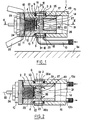
- FIG. 1 shows a thermostatic valve 1 supply of a radiator according to the invention which includes a valve body 2, and an internal shutter 4 controlled to close or open the valve body 2.
- the valve body 2 has a cylindrical portion 3 provided of two orifices 5 opening onto the outer surface 23 of the cylindrical portion 3 and communicating with the shutter 4.
- This chamber circulation 7 ring device ports each orifice 5 of the cylindrical portion 3 with at least an orifice 8 of the sleeve 6.
- valve body 2 has an internal diaphragm 9 and the shutter 4 is controlled in axial translation by relative to valve body 2 to come into contact with the internal diaphragm 9 and seal it or to deviate from it and open it.
- the shutter 4 is mounted on an axial shaft 24 shutter itself mounted on a shutter support 10 associated with a free end 11 of the valve body 2.
- the cylindrical portion 3 of the valve body 2 extends on one side and beyond the diaphragm 9, and the orifices 5 communicate with the diaphragm 9 on the side opposite the shutter 4.
- the shutter support 10 is screwed into a internal thread 12 formed at the end 11 of the body valve 2. This shutter support 10 guides the shaft shutter 24 in axial translation by recalling it in its position away from the diaphragm 9, and carries a device thermostatic control 25 known in itself and represented only partially and schematically on Figure 1.
- the shutter shaft 24 slides in translation axial along an axis 20 of translation which is coincident with the central axis of the diaphragm 9, itself coincident with the axis center of valve body 2 and of cylindrical portion 3.
- the orifices 5 emerging from the cylindrical portion 3 are constituted in the embodiment of Figure 1 of a radial bore 26 passing through the cylindrical portion 3 of right through to communicate with an axial bore 27 extending from the shutter side 4 to form the opening of the diaphragm 9.
- each orifice 5 of the cylindrical portion 3 is in communication with the diaphragm 9 on the side opposite the shutter 4.
- the valve body 2 has one end 14 drain outlet or connection to the appliance or to a pipe 15 of the radiator or of the appliance, and the cylindrical portion 3 extends between this end 14 opening and a peripheral external shoulder 16 against which the sleeve 6 comes to bear axially.
- the shutter 4 extends and moves in a room 22 shutter formed in the valve body 2.
- This chamber 22 is delimited at the end 11 of the valve body 2 opposite the through end 14 between the diaphragm 9 and the threaded end 29 of the shutter support 10 engaged in the internal thread 12 of the valve body 2.
- the diaphragm 9 includes at least one transfer 28 - in particular two transfers 28a, 28b symmetrical to each other by relative to axis 20 - longitudinal connecting the shutter chamber 22 with the through end 14 valve body 2.
- valve 1 has a seal 18 interposed between the sleeve 6 and the pipe 15 of the device (or device), and a seal 19 interposed between the sleeve 6 and the shoulder, the sleeve 6 and the seals 18, 19 being clamped between the pipe 15 of the device (or device) and the shoulder when screwing the external thread 17 into the thread of the line 15 (or of the device).
- External thread 17 and the through end 14 extend axially in the same direction as the axis 20 of translation of the shutter 4.
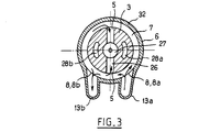
- the sleeve 6 is generally toroidal in shape, the torus generation section is U-shaped whose the opening is oriented towards the axis 20.
- the core 32 of the U defines an external cylindrical wall of the sleeve 6 away from the outer surface 23 of the portion cylindrical 3
- the wings 33 of the U extend radially to form crowns with an internal edge corresponding to the end of wing 33 comes into contact of the outer surface 23 of the cylindrical portion 3.
- the circulation chamber 7 is thus formed between the surface outer 23 of the cylindrical portion 3, the wings 33 and the core 32 of the sleeve 6. Consequently, the water can freely circulate around the cylindrical portion 3 in the chamber 7 circulation.
- Each orifice 8 of the sleeve 6 places the circulation 7 in communication with at least one tube 13 of connection - in particular with two connection tubes 13a, 13b - intended to be connected to a pipe of a central heating installation.
- each connecting tube 13 is bent in the axial direction of the valve body 2, that is to say for extend parallel to axis 20 and end 14 through the valve body 2.
- the sleeve 6 advantageously comprises two orifices 8a, 8b, communicating with the circulation chamber 7 and two tubes 13a, 13b so that you can connect directly the sleeve 6 and the valve according to the invention in parallel to the installation pipeline heater which enters the valve through one of the tubes 13a connection and exit from the valve through the other 13b of connecting tubes.
- the sleeve 6 can have only one connection tube 13, in particular in the case where the valve is intended to be mounted at the end of a pipeline.
- Thermostatic valve 1 shown in Figures 1 to 3 is a valve supply, i.e.
- Valve 1 thermostatic is extremely compact, allows to leave the thermostatic device 25 in perfect position horizontal, parallel to the wall 34 shown in Figure 1 and can be installed instantly on the pipeline 15 of the device itself or on the device by simple screwing.
- the end of the angled connection tubes 13 also includes a thread for connection to the installation pipeline. Connection tubes 13 cubits can extend into the space between the radiator and wall 34.
- Sleeve 6 can be rotated around axis 20 in the proper position for the connection of the tubes 13 for connection to the pipeline of the installation before tightening the valve on the device.
- the valve body 2 consists of a part of a in one piece receiving the shutter support 10 and the sleeve 6.
- the valve 1 is therefore essentially constituted of three parts and seals 18, 19.
- a seal 35 is also interposed between the shutter support 10 and the valve body 2.
- connection tubes 13 are not not necessarily angled and can be simply consisting of threads connecting to the pipeline of the installation extending in a radial plane.
- valves 1 and 36 shown in the figures the water pressure on the shutter 4 tends to open spontaneously this shutter 4. This is indeed essential in thermostatic valves including the shutter 4 is returned to the open position by a spring to prevent the shutter 4 from sticking to the diaphragm 9.
- a valve according to the invention can also include several cylindrical portions 3 and several sleeves 6, or even several shutters 4 depending on the types of desired connection.
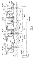
- Figure 4 shows an exemplary embodiment of a central heating installation according to the invention which comprises at least one pipe 43, 44 and at least an apparatus 45 connected to the pipe 43, 44 by a valve 1 or 36 according to the invention.
- Line 43, 44 of such an installation according to the invention can be in semi-rigid plastic - especially cross-linked PVC - and be free from embedded connections in the ground 46 or in walls 34, the valve connection in parallel to the piping taking place directly on the valve itself which comprises two connection tubes 13a, 13b.
- the central heating installation of Figure 5 includes a supply line 43 coming from a boiler room or nurse 47 and a pipeline from return 44 to the boiler room or nurse 47, and at least a radiator 45 provided with at least one valve 1 or 36 according to the invention.
- each radiator 45 comprises a supply valve 1 or 36 according to the invention.
- Each radiator 45 is connected to the pipeline supply 43 in parallel by a supply valve 1 to two connection tubes 13a, 13b except for the last radiator 45c - that is to say the most downstream on the supply line 43 - which includes a supply valve 1 having only one connection tube 13. Indeed, for the last 45c radiator, the entire water flow arriving in the connection tube 13 must pass inside the radiator 45c until its outlet 48c.
- the supply line comprises a first portion 43a connecting the nurse 47 to the valve thermostatic 1a of the first radiator 45a.
- This pipe 43a is connected to connection tube 13a inlet valve 1a.
- the through end of this valve 1a is connected to line 15a of the first radiator 45a.
- the outlet connection tube 13b is connected to an intermediate portion 43b of the pipeline that connects continuously and without connection this supply valve 1a to supply valve 1b of a intermediate radiator 45b.
- the intermediate pipeline 43b from the first radiator 45a is therefore connected to the valve inlet connection tube 13a thermostatic 1b.
- Another intermediate pipeline supply 43b is connected to the connection tube 13b outlet of this valve 1b to connect this radiator 45b to a subsequent intermediate radiator 45b.
- Valve 1b supply of an intermediate radiator 45b to its through end 14 connected to the pipe 15b of the radiator.
- the last radiator 45c is connected to the radiator intermediate 45b immediately upstream with a final portion 43c of the supply line 43 which is connected to the connection tube 13 of the valve 1c of this last radiator 45c.
- the through end 14 of this valve 1c communicates with the pipe 15c of the latter 45c radiator.
- the outputs 48 of the radiators 45 are connected together in parallel, the output 48c of the last radiator 45c being connected to the pipe of back 44 to nurse 47.
- a manually operated outlet valve 36 such as shown in Figure 4. So in a installation according to the invention outlet 48 of at least one radiator 45 is fitted with an outlet valve according to the invention.
- the first outlet valve 36a connected to the outlet 48a of the first radiator 45a has a single tube connection 13 which is connected to a first portion 44a from the return line. This first portion 44a is connected to the inlet connection tube 13a of a outlet valve 36b of an intermediate radiator 45b.
- each radiator comprises a valve supply 1 fitted with a thermostatic device control 25 and an outlet valve 36 fitted with a manual control device 37.
- Each portion of pipe can be made of plastic semi-rigid such as cross-linked PVC and no connection recessed is not necessary in the walls or in the ground, all connections being made on valves 1 or 36.
- the sleeves 6 of the valves make it possible to facilitate greatly the installation and installation of radiators in slightly varying the orientation of the connection 13.
- the invention also relates to a radiator 45 central heating installation that includes a valve supply 1 and / or an outlet valve 36 according to the invention.
Landscapes
- Engineering & Computer Science (AREA)
- General Engineering & Computer Science (AREA)
- Chemical & Material Sciences (AREA)
- Thermal Sciences (AREA)
- Combustion & Propulsion (AREA)
- Mechanical Engineering (AREA)
- Physics & Mathematics (AREA)
- Valve Housings (AREA)
- Chair Legs, Seat Parts, And Backrests (AREA)
- Steam Or Hot-Water Central Heating Systems (AREA)
- Self-Closing Valves And Venting Or Aerating Valves (AREA)
- Details Of Valves (AREA)
- Pipe Accessories (AREA)
Claims (19)
- Ventil für eine Heizungsanlage, das ein Ventilgehäuse (2) und ein in einer Kammer (22) des Ventilgehäuses (2) angeordnetes inneres Ventilverschlussglied (4) aufweist, das im Sinne eines Öffnens und Schließens des Ventils (2,38) zu steuern ist, wobei das Gehäuse (2) wenigstens einen zylindrischen Abschnitt (3) aufweist, der mit wenigstens einer Öffnung (5) versehen ist, die an der Außenumfangsfläche (23) des zylindrischen Teils (3) mündet und die mit dem Absperrglied (49 in Verbindung steht; und zu dem Ventil ferner eine Manschette (6), die den zylindrischen Teil umgibt, und wenigstens eine Öffnung (8) gehören, die einerseits mit der Öffnung (5) des zylindrischen Abschnittes (3) und andererseits mit wenigstens einem Anschlussrohr (13) strömungsmäßig in Verbindung steht, das dazu vorgesehen ist, an einem Rohrsystem einer Zentralheizungsanlage angeschlossen zu werden, dadurch gekennzeichnet, dass das Ventilgehäuse (2) eine innere Blende (9) enthält, in der alle Öffnungen (5) vorgesehen sind, die mit einer axialen Bohrung (27) der Blende strömungsmäßig in Verbindung stehen, die in Richtung auf das Verschlußglied (4) offen ist, ebenso wie wenigstens ein Längskanal (28) der Blende (9) aufweist, der die Kammer (22) des Gehäuses (2) mit einem Auslassanschluss (14) des Gehäuses (2) strömungsmäßig verbindet, in der Weise, dass das Wasser, frei um den zylindrischen Teil (3) zirkulieren kann, indem es die Öffnungen (5) passiert, um in die Kammer (7) einzumünden; und
dass das Ventilverschlussglied (4, 39) bezüglich des Ventilgehäuses (2) axial bewegbar ist, um mit der inneren Blende (9) in Berührung zu kommen und die Axialbohrung (27) zu verschließen oder um sich von dieser zu entfernen und diese frei zu geben. - Ventil nach Anspruch 1, dadurch gekennzeichnet, dass die Manschette (6) wenigstens eine Öffnung (8) aufweist, die einerseits mit allen Öffnungen (5) des zylindrischen Abschnittes (3) und andererseits mit wenigstens einem Anschlussrohr (13) strömungsmäßig in Verbindung steht, das dazu vorgesehen ist, an das Rohrleitungssystem einer Zentralheizungsanlage ohne Anschlüsse im Boden oder in den Wänden angeschlossen zu werden, wohingegen sich der zylindrische Teil (3) des Ventilgehäuses (2,38) an einer Seite und jenseits der Membrane (9,41) erstreckt, und das Ventilverschlussglied (4,39) auf einem Ventilverschlussgliedhalter (10,40) gelagert ist, der einem freien Ende (11) des Ventilgehäuses (238) zugeordnet ist.
- Ventil nach Anspruch 2, dadurch gekennzeichnet, dass der Halter (10,40) in ein Innengewinde (12) des Ventilgehäuses (2,38) eingeschraubt ist.
- Ventil nach einem der Ansprüche 1 bis 3, dadurch gekennzeichnet, dass alle Anschlussrohre (13) in Richtung parallel zu der Achse des Ventilgehäuses (2,38) umgebogen sind.
- Ventil nach einem der Ansprüche 1 bis 4, dadurch gekennzeichnet, dass die Manschette (6) zwei Öffnungen (8a, 8b) sowie zwei Anschlussrohre (13a,13b) aufweist.
- Ventil nach einem der Ansprüche 1 bis 5, dadurch gekennzeichnet, dass das Ventilgehäuse (2,38) einen Auslassanschluss (14) oder einen Anschluss für eine Rohrleitung eines Heizkörpers oder einen Heizkörper aufweist, und dass sich der zylindrische Abschnitt (3) zwischen diesem Auslassanschluss (14) und einer äußeren am Umfang gelegenen Schulter (16) erstreckt, gegen die die Manschette (6) anliegt.
- Ventil nach Anspruch 6, dadurch gekennzeichnet, dass der Auslassanschluss (14) ein Außengewinde (17) zum Befestigen aufweist, und das das Ventil an jeder Seite der Manschette (6) eine Dichtung (18,19) aufweist, die zwischen die Rohrleitung des Gerätes oder das Gerät und der Schulter (16) beim Einschrauben des Außengewindes (17) eingefügt wird.
- Ventil nach Anspruch 7, dadurch gekennzeichnet, dass das Außengewinde (17) und der Auslassanschluss (14) sich axial in die selbe Richtung erstrecken, wie die Bewegungsachse (20) des Ventilverschlussgliedes (4,39).
- Ventil nach einem der Ansprüche 1 bis 8, dadurch gekennzeichnet, dass alle Öffnungen (5) des zylindrischen Teils (3) mit der Blende (9) auf der von dem Ventilverschlussglied (4) abliegenden Seite strömungsmäßig in Verbindung stehen, und dass die Blende (9) wenigstens einen Längskanal (28) aufweist, um eine Strömungsverbindung zwischen der das Ventilverschlussglied (4) enthaltenen Kammer des Ventilgehäuses (2) und dem Auslassanschluss (14) des Ventilgehäuses (2) herzustellen.
- Zentralheizungsanlage mit wenigstens einem Rohrkreislauf (43,44) und wenigstens einem Heizkörper, der an den Rohrkreislauf (43,44) über ein Ventil (1,36) nach einem der Ansprüche 1 bis 9 angeschlossen ist.
- Anlage nach Anspruch 10, dadurch gekennzeichnet, dass der Rohrkreislauf ohne Anschlüsse im Boden oder in den Wänden aus einem halbstarren Kunststoffmaterial besteht.
- Zentralheizungsanlage, zu der eine Vorlaufleitung (43), die von einer Wärmequelle kommt, und eine Rücklaufleitung (44), die zu der Wärmequelle führt, sowie wenigstens ein Radiator (45) gehören, der mit wenigstens einem Ventil (1, 36) nach einem der Ansprüche 1 bis 9 versehen ist.
- Anlage nach Anspruch 12, dadurch gekennzeichnet, dass jeder Radiator ein Vorlaufventil (1, 36) nach einem der Ansprüche 1 bis 9 aufweist.
- Anlage nach einem der Ansprüche 12 und 13, dadurch gekennzeichnet, dass jeder Radiator (45) parallel an eine Vorlaufleitung (43) über ein Vorlaufventil (1) mit zwei Anschlussrohre (13a, 13b) angeschlossen ist, mit Ausnahme des letzen Radiators (45), der ein Vorlaufventil (1) mit einem Anschlussrohr (13) aufweist.
- Anlage nach einem der Ansprüche 12 bis 14, dadurch gekennzeichnet, dass alle Auslässe (48) aller Radiatoren (45) zueinander parallel angeschlossen sind, und dass der Auslass (48c) des letzen Radiators (45c) an die Rücklaufleitung (44) angeschlossen ist.
- Anlage nach einem der Ansprüche 12 bis 15, dadurch gekennzeichnet, dass der Auslass (48) wenigstens eines Radiators (45) mit einem Rücklaufventil (36) nach einem der Ansprüche 1 bis 9 versehen ist.
- Anlage nach einem der Ansprüche 12 bis 16, dadurch gekennzeichnet, dass jeder Radiator ein Vorlaufventil (19 aufweist, das mit einer thermostatischen Steuereinrichtung (25) versehen ist, sowie mit einem Rücklaufventil (36), das mit einer manuellen Betätigungseinrichtung (37) versehen ist.
- Heizkörper einer Zentralheizungsanlage, dadurch gekennzeichnet, dass er ein Vorlaufventil (1) nach einem der Ansprüche 1 bis 9 aufweist.
- Heizkörper nach Anspruch 18, dadurch gekennzeichnet, dass das Vorlaufventil (1) mit einer thermostatischen Steuereinrichtung (25) versehen ist und dass das Rücklaufventil mit einer manuellen Betätigungseinrichtung (37) versehen ist.
Applications Claiming Priority (2)
| Application Number | Priority Date | Filing Date | Title |
|---|---|---|---|
| FR9212862A FR2697322B1 (fr) | 1992-10-28 | 1992-10-28 | Vanne pour installation de chauffage ou sanitaire à manchon de raccord, installation sanitaire ou de chauffage central et radiateur comportant au moins une telle vanne. |
| FR9212862 | 1992-10-28 |
Publications (2)
| Publication Number | Publication Date |
|---|---|
| EP0595718A1 EP0595718A1 (de) | 1994-05-04 |
| EP0595718B1 true EP0595718B1 (de) | 1999-12-15 |
Family
ID=9434928
Family Applications (1)
| Application Number | Title | Priority Date | Filing Date |
|---|---|---|---|
| EP93402636A Expired - Lifetime EP0595718B1 (de) | 1992-10-28 | 1993-10-27 | Ventil mit Anschlussstutzen für Heizungsanlage, Heizungsanlage und Heizkörper mit wenigstens einem solchen Ventil |
Country Status (5)
| Country | Link |
|---|---|
| EP (1) | EP0595718B1 (de) |
| AT (1) | ATE187815T1 (de) |
| DE (1) | DE69327299T2 (de) |
| ES (1) | ES2139639T3 (de) |
| FR (1) | FR2697322B1 (de) |
Family Cites Families (3)
| Publication number | Priority date | Publication date | Assignee | Title |
|---|---|---|---|---|
| FR1362559A (fr) * | 1963-04-13 | 1964-06-05 | Finissage De Produits Metallur | Raccord orientable |
| IT1183037B (it) | 1985-12-04 | 1987-10-05 | R B Raccorderie Bresciane S R | Collettore-deviatore per fluidi con asse di derivazione orientabile |
| DE4011111C1 (en) * | 1990-04-06 | 1991-08-01 | F.W. Oventrop Kg, 5787 Olsberg, De | Panel radiator connection - has feed and return connections joined to connection piece linking two radiator panels and screwed in place |
-
1992
- 1992-10-28 FR FR9212862A patent/FR2697322B1/fr not_active Expired - Fee Related
-
1993
- 1993-10-27 ES ES93402636T patent/ES2139639T3/es not_active Expired - Lifetime
- 1993-10-27 DE DE69327299T patent/DE69327299T2/de not_active Expired - Fee Related
- 1993-10-27 EP EP93402636A patent/EP0595718B1/de not_active Expired - Lifetime
- 1993-10-27 AT AT93402636T patent/ATE187815T1/de not_active IP Right Cessation
Also Published As
| Publication number | Publication date |
|---|---|
| ES2139639T3 (es) | 2000-02-16 |
| DE69327299T2 (de) | 2000-07-20 |
| ATE187815T1 (de) | 2000-01-15 |
| FR2697322A1 (fr) | 1994-04-29 |
| EP0595718A1 (de) | 1994-05-04 |
| DE69327299D1 (de) | 2000-01-20 |
| FR2697322B1 (fr) | 1994-12-30 |
Similar Documents
| Publication | Publication Date | Title |
|---|---|---|
| US7681596B2 (en) | Isolation valve with valve in drain | |
| US7621295B2 (en) | System for controlling fluid flow to an appliance | |
| EP1155271B1 (de) | Plattenwärmetauscher mit integriertem ventil | |
| FR2914044A1 (fr) | Raccord destine a raccorder un tube avec une nourrice | |
| FR3054634A1 (fr) | Clapet a bille avec robinet de purge incorpore | |
| KR20090042119A (ko) | 유체 분배기 | |
| FR2472707A1 (fr) | Dispositif pour la commande de l'alimentation en liquide d'un appareil, notamment d'un echangeur de chaleur, en particulier pour vehicule automobile | |
| FR2697322A1 (fr) | Vanne pour installation de chauffage ou sanitaire à manchon de raccord, installation sanitaire ou de chauffage central et radiateur comportant au moins une telle vanne. | |
| FR2590655A1 (fr) | Appareil de cuisson a gaz | |
| RU2215220C2 (ru) | Вентиль, в частности вентиль радиатора отопления | |
| FR2486194A1 (fr) | Dispositif de raccordement pour tuyauteries de circulation de fluides et dispositif de commande de la circulation de fluides comportant un tel dispositif de raccordement | |
| FR2704293A1 (fr) | Robinet à tournant cylindrique. | |
| FR2649464A1 (fr) | Robinet a boisseau | |
| FR2527736A1 (fr) | Vanne magnetique | |
| FR2860057A3 (fr) | Dispositif de valve d'interception et de regulation d'ecoulement pour radiateurs | |
| EP0671515B1 (de) | Sicherheitsvorrichtung zum Einbauen zwischen einer Leitung eines Trinkwasserleitungsnetzes und einer Versorgungsleitung eines Verbrauchergeräts, wie ein Heizkessel | |
| FR2803025A1 (fr) | Echangeur thermique a plaques, a clapet de decharge integre | |
| EP2966325A1 (de) | Kugelventil | |
| EP0533514A1 (de) | Regelungsmittel für Heizungsflüssigkeit | |
| FR2864151A1 (fr) | Boitier de sortie d'eau | |
| FR2640020A3 (fr) | Robinet anti-fuite a cones inverses | |
| FR2826435A1 (fr) | Robinetterie de raccordement pour radiateurs | |
| FR2528531A1 (fr) | Raccord collecteur modulaire pour la distribution de fluide | |
| GB2300695A (en) | A water supply assembly | |
| FR2973855A1 (fr) | Dispositif de sertissage interieur et exterieur |
Legal Events
| Date | Code | Title | Description |
|---|---|---|---|
| PUAI | Public reference made under article 153(3) epc to a published international application that has entered the european phase |
Free format text: ORIGINAL CODE: 0009012 |
|
| AK | Designated contracting states |
Kind code of ref document: A1 Designated state(s): AT BE CH DE DK ES FR GB GR IE IT LI NL PT SE |
|
| 17P | Request for examination filed |
Effective date: 19941209 |
|
| 17Q | First examination report despatched |
Effective date: 19951121 |
|
| GRAG | Despatch of communication of intention to grant |
Free format text: ORIGINAL CODE: EPIDOS AGRA |
|
| TPAD | Observations filed by third parties |
Free format text: ORIGINAL CODE: EPIDOS TIPA |
|
| GRAG | Despatch of communication of intention to grant |
Free format text: ORIGINAL CODE: EPIDOS AGRA |
|
| GRAG | Despatch of communication of intention to grant |
Free format text: ORIGINAL CODE: EPIDOS AGRA |
|
| GRAG | Despatch of communication of intention to grant |
Free format text: ORIGINAL CODE: EPIDOS AGRA |
|
| GRAH | Despatch of communication of intention to grant a patent |
Free format text: ORIGINAL CODE: EPIDOS IGRA |
|
| GRAH | Despatch of communication of intention to grant a patent |
Free format text: ORIGINAL CODE: EPIDOS IGRA |
|
| GRAA | (expected) grant |
Free format text: ORIGINAL CODE: 0009210 |
|
| RIN1 | Information on inventor provided before grant (corrected) |
Inventor name: ALEXANDRE, NOEL |
|
| AK | Designated contracting states |
Kind code of ref document: B1 Designated state(s): AT BE CH DE DK ES FR GB GR IE IT LI NL PT SE |
|
| PG25 | Lapsed in a contracting state [announced via postgrant information from national office to epo] |
Ref country code: SE Free format text: THE PATENT HAS BEEN ANNULLED BY A DECISION OF A NATIONAL AUTHORITY Effective date: 19991215 Ref country code: NL Free format text: LAPSE BECAUSE OF FAILURE TO SUBMIT A TRANSLATION OF THE DESCRIPTION OR TO PAY THE FEE WITHIN THE PRESCRIBED TIME-LIMIT Effective date: 19991215 Ref country code: GR Free format text: LAPSE BECAUSE OF NON-PAYMENT OF DUE FEES Effective date: 19991215 Ref country code: AT Free format text: LAPSE BECAUSE OF FAILURE TO SUBMIT A TRANSLATION OF THE DESCRIPTION OR TO PAY THE FEE WITHIN THE PRESCRIBED TIME-LIMIT Effective date: 19991215 |
|
| REF | Corresponds to: |
Ref document number: 187815 Country of ref document: AT Date of ref document: 20000115 Kind code of ref document: T |
|
| REG | Reference to a national code |
Ref country code: CH Ref legal event code: EP |
|
| REF | Corresponds to: |
Ref document number: 69327299 Country of ref document: DE Date of ref document: 20000120 |
|
| REG | Reference to a national code |
Ref country code: ES Ref legal event code: FG2A Ref document number: 2139639 Country of ref document: ES Kind code of ref document: T3 |
|
| REG | Reference to a national code |
Ref country code: IE Ref legal event code: FG4D |
|
| ITF | It: translation for a ep patent filed | ||
| GBT | Gb: translation of ep patent filed (gb section 77(6)(a)/1977) |
Effective date: 20000222 |
|
| PG25 | Lapsed in a contracting state [announced via postgrant information from national office to epo] |
Ref country code: PT Free format text: LAPSE BECAUSE OF FAILURE TO SUBMIT A TRANSLATION OF THE DESCRIPTION OR TO PAY THE FEE WITHIN THE PRESCRIBED TIME-LIMIT Effective date: 20000315 Ref country code: DK Free format text: LAPSE BECAUSE OF FAILURE TO SUBMIT A TRANSLATION OF THE DESCRIPTION OR TO PAY THE FEE WITHIN THE PRESCRIBED TIME-LIMIT Effective date: 20000315 |
|
| NLV1 | Nl: lapsed or annulled due to failure to fulfill the requirements of art. 29p and 29m of the patents act | ||
| PLBE | No opposition filed within time limit |
Free format text: ORIGINAL CODE: 0009261 |
|
| STAA | Information on the status of an ep patent application or granted ep patent |
Free format text: STATUS: NO OPPOSITION FILED WITHIN TIME LIMIT |
|
| PG25 | Lapsed in a contracting state [announced via postgrant information from national office to epo] |
Ref country code: LI Free format text: LAPSE BECAUSE OF NON-PAYMENT OF DUE FEES Effective date: 20001031 Ref country code: CH Free format text: LAPSE BECAUSE OF NON-PAYMENT OF DUE FEES Effective date: 20001031 Ref country code: BE Free format text: LAPSE BECAUSE OF NON-PAYMENT OF DUE FEES Effective date: 20001031 |
|
| PG25 | Lapsed in a contracting state [announced via postgrant information from national office to epo] |
Ref country code: IE Free format text: LAPSE BECAUSE OF NON-PAYMENT OF DUE FEES Effective date: 20001116 |
|
| 26N | No opposition filed | ||
| REG | Reference to a national code |
Ref country code: IE Ref legal event code: FD4D |
|
| BERE | Be: lapsed |
Owner name: ALEXANDRE NOEL Effective date: 20001031 Owner name: S.A. GRIPP Effective date: 20001031 |
|
| REG | Reference to a national code |
Ref country code: CH Ref legal event code: PL |
|
| REG | Reference to a national code |
Ref country code: GB Ref legal event code: IF02 |
|
| PGFP | Annual fee paid to national office [announced via postgrant information from national office to epo] |
Ref country code: DE Payment date: 20071108 Year of fee payment: 15 |
|
| PGFP | Annual fee paid to national office [announced via postgrant information from national office to epo] |
Ref country code: IT Payment date: 20071026 Year of fee payment: 15 |
|
| PGFP | Annual fee paid to national office [announced via postgrant information from national office to epo] |
Ref country code: GB Payment date: 20071019 Year of fee payment: 15 |
|
| GBPC | Gb: european patent ceased through non-payment of renewal fee |
Effective date: 20081027 |
|
| PG25 | Lapsed in a contracting state [announced via postgrant information from national office to epo] |
Ref country code: IT Free format text: LAPSE BECAUSE OF NON-PAYMENT OF DUE FEES Effective date: 20081027 Ref country code: DE Free format text: LAPSE BECAUSE OF NON-PAYMENT OF DUE FEES Effective date: 20090501 |
|
| PG25 | Lapsed in a contracting state [announced via postgrant information from national office to epo] |
Ref country code: GB Free format text: LAPSE BECAUSE OF NON-PAYMENT OF DUE FEES Effective date: 20081027 |
|
| REG | Reference to a national code |
Ref country code: FR Ref legal event code: TP Owner name: WATTS INDUSTRIES FRANCE, FR Effective date: 20120719 |
|
| PGFP | Annual fee paid to national office [announced via postgrant information from national office to epo] |
Ref country code: FR Payment date: 20121126 Year of fee payment: 20 |
|
| REG | Reference to a national code |
Ref country code: ES Ref legal event code: PC2A Owner name: WATTS INDUSTRIES FRANCE Effective date: 20130129 |
|
| PGFP | Annual fee paid to national office [announced via postgrant information from national office to epo] |
Ref country code: ES Payment date: 20121022 Year of fee payment: 20 |
|
| REG | Reference to a national code |
Ref country code: FR Ref legal event code: TQ Owner name: ALEXANDRE NOEL, FR Effective date: 20130205 Ref country code: FR Ref legal event code: TQ Owner name: WATTS INDUSTRIES FRANCE, FR Effective date: 20130205 |
|
| REG | Reference to a national code |
Ref country code: ES Ref legal event code: FD2A Effective date: 20140108 |
|
| PG25 | Lapsed in a contracting state [announced via postgrant information from national office to epo] |
Ref country code: ES Free format text: LAPSE BECAUSE OF EXPIRATION OF PROTECTION Effective date: 20131028 |