EP0761888A1 - Entfernbarer verriegelbarer Poller - Google Patents
Entfernbarer verriegelbarer Poller Download PDFInfo
- Publication number
- EP0761888A1 EP0761888A1 EP96420286A EP96420286A EP0761888A1 EP 0761888 A1 EP0761888 A1 EP 0761888A1 EP 96420286 A EP96420286 A EP 96420286A EP 96420286 A EP96420286 A EP 96420286A EP 0761888 A1 EP0761888 A1 EP 0761888A1
- Authority
- EP
- European Patent Office
- Prior art keywords
- cover
- base
- well
- terminal
- bolt
- Prior art date
- Legal status (The legal status is an assumption and is not a legal conclusion. Google has not performed a legal analysis and makes no representation as to the accuracy of the status listed.)
- Granted
Links
- 230000000295 complement effect Effects 0.000 claims description 3
- 230000002093 peripheral effect Effects 0.000 claims description 3
- 238000000605 extraction Methods 0.000 description 11
- 241001310793 Podium Species 0.000 description 1
- 238000010276 construction Methods 0.000 description 1
- 230000000694 effects Effects 0.000 description 1
- 238000009434 installation Methods 0.000 description 1
- 238000012423 maintenance Methods 0.000 description 1
Images

Classifications
-
- E—FIXED CONSTRUCTIONS
- E01—CONSTRUCTION OF ROADS, RAILWAYS, OR BRIDGES
- E01F—ADDITIONAL WORK, SUCH AS EQUIPPING ROADS OR THE CONSTRUCTION OF PLATFORMS, HELICOPTER LANDING STAGES, SIGNS, SNOW FENCES, OR THE LIKE
- E01F13/00—Arrangements for obstructing or restricting traffic, e.g. gates, barricades ; Preventing passage of vehicles of selected category or dimensions
- E01F13/02—Arrangements for obstructing or restricting traffic, e.g. gates, barricades ; Preventing passage of vehicles of selected category or dimensions free-standing; portable, e.g. for guarding open manholes ; Portable signs or signals specially adapted for fitting to portable barriers
- E01F13/024—Removable barriers with permanently installed base members, e.g. to provide occasional passage
- E01F13/026—Detachable barrier bollards or parking posts
-
- E—FIXED CONSTRUCTIONS
- E01—CONSTRUCTION OF ROADS, RAILWAYS, OR BRIDGES
- E01F—ADDITIONAL WORK, SUCH AS EQUIPPING ROADS OR THE CONSTRUCTION OF PLATFORMS, HELICOPTER LANDING STAGES, SIGNS, SNOW FENCES, OR THE LIKE
- E01F9/00—Arrangement of road signs or traffic signals; Arrangements for enforcing caution
- E01F9/60—Upright bodies, e.g. marker posts or bollards; Supports for road signs
- E01F9/658—Upright bodies, e.g. marker posts or bollards; Supports for road signs characterised by means for fixing
- E01F9/673—Upright bodies, e.g. marker posts or bollards; Supports for road signs characterised by means for fixing for holding sign posts or the like
- E01F9/685—Subsoil means, e.g. foundations
Definitions
- the invention relates to a lockable removable terminal used in public spaces to mark and organize pedestrian traffic and the parking of cars and other mobiles.
- It relates more particularly to the removable terminals which can be removed to free the passage or to clear the ground, for example to make temporary constructions such as podium or marquee.
- bollards relates to the terminals in which the sole is extended by a tubular barrel which, of smaller diameter than it, is fitted into the vertical well of a base sealed in the ground.
- Such bollards must meet many safety rules. Indeed, they must not be able to be removed by an unauthorized person, to guarantee their function, and above all to avoid that the well of the base, whose mouth is flush with the ground level, constitutes a source of accident for pedestrians.
- the object of the present invention is to remedy these drawbacks by providing a removable bollard provided with locking means opposing the removal of any of its elements, bollard or cover, for any unauthorized person and eliminating the risks consecutive in the absence of a cover after extraction of the terminal.
- the base comprises on the one hand, in its upper and outer part, a radial lug provided with a lower bearing for the rotor of a pivoting bolt and a bearing upper for the imprisonable end of a removable key for actuating the rotor, on the other hand, and in the bottom of its vertical well, a vertical housing capable of receiving all or part of the cover, and, in addition and projecting of the internal cylindrical face of its well, vertical positioning ribs, while the bole of the terminal has a lower flange with radial notches capable of cooperating with the ribs of the well and laterally of a radial fin capable of come under the pivoting trajectory of the bolt, and that the cover comprises, near its peripheral edge, on the one hand, positioning fingers projecting downward and capable of cooperating with one vertical ribs of the well, and, on the other hand, a keeper capable of receiving the end of the bolt.
- the cover can be stored inside the base when not in use, which makes it possible, during the extraction of the terminal, to very quickly close the well of this base. .
- the cover is engaged again in the base housing. This arrangement simplifies the task of maintenance personnel and considerably reduces the risk of accidents.
- the cover is locked by the same means as those locking the terminal, which prevents its extraction by an unauthorized person.
- the rotor of the pivoting bolt comprises a head which, projecting axially in the upper bearing for the end piece of the key, has in cross section an asymmetrical profile complementary to that internal to the end piece, while the upper bearing has at least one longitudinal groove which, opening into a housing provided for the bolt between the two bearings, allows the passage of at least one lug projecting radially from the tip of the key.
- the particular profile of the rotor head is opposed to its actuation by standard commercial keys, while the lug is opposed to any extraction of the key when its tip has been engaged in the upper bearing and pivoted to bring the mechanism in unlocked position.
- This constructive arrangement therefore makes it possible to extract the key only when the mechanism is brought into the locking position and therefore encourages personnel wishing to recover their key, after extraction of the terminal, to put the cover in place and to lock it.
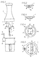
- this lockable removable terminal is composed of a terminal 2, the sole 3 of which is integral with a tubular barrel 4, of diameter smaller than that of the sole, and a base 5 sealable in the ground and comprising an axial well 6 for receiving the barrel 4 of the base.
- This base can also receive a cover 7. It is provided with a locking mechanism which can be actuated by a removable key 8.
- the base 5 has, at its upper part, and as shown in FIG. 5, a radial lug 10 projecting outwards.
- this lug and provided with an upper bearing 12 and a lower bearing 13 for the rotor 14 of the locking mechanism, constituted here by a rotary bolt 15 driven in rotation by the head 14a of the rotor 14.
- This bolt is disposed, in part, in a housing 16 formed between the two bearings 12 and 13.
- the head 14a forms an axial projection in the upper bearing 12.
- This head has, in cross section, a shape not symmetrical or not compatible with the standard forms of traditional keys, so as to oppose its rotation drive by an unsuitable tool. It is obvious that the shape of this head is complementary to the internal profile of the end piece 8a of the key 8.
- the key 8 is moreover provided with at least one and in this case two lugs 17 which can reach the housing 16 of the ear 10 by virtue of vertical grooves 11 formed in the bearing 12, visible in FIG. 5.
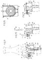
- the vertical well 6 of the base is extended beyond its bottom 6a by a vertical housing 18, arranged diametrically and capable of containing all or part of the cover 7. As shown in FIG. 12, this housing is capable of receiving at least the lower half of the cover 7, the other half of which is housed in part in the barrel 4 of the terminal 2.
- the cover comprises near its peripheral edge, on the one hand, two positioning fingers 19 projecting downward and on the other hand, a cavity 20 forming a keeper for the bolt 15.
- the fingers 19 are diametrically opposite the keeper 20.
- the facing edges 19a of the two fingers form a flared light downwards.
- Figures 6 to 8 show that, when the cover is in the housing 18, it is positioned with its keeper 20 facing downwards and so that its two fingers 19 are positioned on either side of one of the ribs vertical 22 projecting inside the barrel 4 of the terminal 2.
- the base 5 comprises, projecting from the internal face of its well 6, and as shown in FIG. 5, several vertical ribs 23 and 24.
- This Figure also shows that the housing 18 for the cover has, at its bottom, a clearance 25 for angular positioning of the keeper 20 of the cover.
- the barrel 4 of terminal 2 is provided with a collar 26 which has radial notches 23a and 24a corresponding to the ribs 23 and 24 of the well 6 and intended to ensure the angular positioning of this terminal during its implementation place in this barrel. This positioning is necessary to orient, relative to the locking device, a radial fin 27 projecting from the barrel of the terminal and which, as shown in Figures 6 and 7, is intended to cooperate with the rotary bolt 15 of the locking mechanism.
- the barrel 4 is provided with two diametrically opposite cutouts 28 facilitating the passage of the upper part of the cover when this barrel is placed in the base.
- the housing 12a of the bearing 12, formed in the ear 10 of the base is normally closed by a plug 30, as shown in FIG. 6.
- the cover is in turn extracted (FIG. 10), then placed on the mouth of the well 6. During this positioning, it is angularly positioned so that the two fingers 19 are arranged on either side of the rib 23 projecting inside the barrel, then is pressed. During this maneuver, the sloping edges 19a of the fingers 19 cooperate with the rib 23 to ensure precise angular positioning of the cover, so that its keeper 20 comes in perfect coincidence with the trajectory of the bolt 15. In a following phase, the bolt is returned to the locked position, the key 8 is extracted and the plug 30 is replaced.
- the operator When replacing the terminal, the operator is obliged to correctly position the cover, failing which his fingers 19, larger than the width of the housing 18, oppose the complete engagement of the cover in this housing, which prevents the subsequent installation of the keg of the terminal.
- the ribs 23 and 24 of the was obligate to radially position the notches 23a, 24a of the terminal failing which the flange 26 thereof cannot penetrate into the well.
Landscapes
- Engineering & Computer Science (AREA)
- Architecture (AREA)
- Civil Engineering (AREA)
- Structural Engineering (AREA)
- Connector Housings Or Holding Contact Members (AREA)
- Acyclic And Carbocyclic Compounds In Medicinal Compositions (AREA)
- Closures For Containers (AREA)
- Orthopedics, Nursing, And Contraception (AREA)
- Soil Working Implements (AREA)
- Refuge Islands, Traffic Blockers, Or Guard Fence (AREA)
Applications Claiming Priority (2)
| Application Number | Priority Date | Filing Date | Title |
|---|---|---|---|
| FR9510689A FR2738267B1 (fr) | 1995-09-05 | 1995-09-05 | Borne amovible verrouillable |
| FR9510689 | 1995-09-05 |
Publications (2)
| Publication Number | Publication Date |
|---|---|
| EP0761888A1 true EP0761888A1 (de) | 1997-03-12 |
| EP0761888B1 EP0761888B1 (de) | 1999-10-20 |
Family
ID=9482480
Family Applications (1)
| Application Number | Title | Priority Date | Filing Date |
|---|---|---|---|
| EP96420286A Expired - Lifetime EP0761888B1 (de) | 1995-09-05 | 1996-09-03 | Entfernbarer verriegelbarer Poller |
Country Status (5)
| Country | Link |
|---|---|
| EP (1) | EP0761888B1 (de) |
| AT (1) | ATE185859T1 (de) |
| DE (1) | DE69604754T2 (de) |
| ES (1) | ES2138800T3 (de) |
| FR (1) | FR2738267B1 (de) |
Cited By (1)
| Publication number | Priority date | Publication date | Assignee | Title |
|---|---|---|---|---|
| ES2345920A1 (es) * | 2010-03-16 | 2010-10-05 | Sabacaucho S.A. | Base encofrada para una pilona extraible. |
Families Citing this family (1)
| Publication number | Priority date | Publication date | Assignee | Title |
|---|---|---|---|---|
| ES2302594B1 (es) * | 2005-12-30 | 2009-05-20 | Celaya Emparanza Y Galdos Internacional, S.A. | Baliza cilindrica permanente para señalizacion vertical de carretera. |
Citations (6)
| Publication number | Priority date | Publication date | Assignee | Title |
|---|---|---|---|---|
| US2259610A (en) * | 1940-01-31 | 1941-10-21 | Leland S Dougan | Removable and replaceable traffic marker |
| DE2002452A1 (de) * | 1970-01-21 | 1971-07-29 | Theodor Laudahn | Bodenhuelse mit Verschluss-Klappdeckel fuer ein Staenderrohr |
| GB2125084A (en) * | 1982-08-10 | 1984-02-29 | Gray Securities | A security upright |
| GB2209785A (en) * | 1987-09-14 | 1989-05-24 | Eamonn William Joseph Kelly | Security post with fixed cover to base tube |
| FR2630169A1 (fr) * | 1988-04-18 | 1989-10-20 | Verra Yvan | Installation pour l'amenagement amovible et verrouillable de tout mobilier |
| DE29504110U1 (de) * | 1995-02-02 | 1995-06-08 | Schäper, Klemens, 48161 Münster | Deckelanordnung für eine Bodenhülse |
-
1995
- 1995-09-05 FR FR9510689A patent/FR2738267B1/fr not_active Expired - Fee Related
-
1996
- 1996-09-03 AT AT96420286T patent/ATE185859T1/de not_active IP Right Cessation
- 1996-09-03 EP EP96420286A patent/EP0761888B1/de not_active Expired - Lifetime
- 1996-09-03 DE DE69604754T patent/DE69604754T2/de not_active Expired - Fee Related
- 1996-09-03 ES ES96420286T patent/ES2138800T3/es not_active Expired - Lifetime
Patent Citations (6)
| Publication number | Priority date | Publication date | Assignee | Title |
|---|---|---|---|---|
| US2259610A (en) * | 1940-01-31 | 1941-10-21 | Leland S Dougan | Removable and replaceable traffic marker |
| DE2002452A1 (de) * | 1970-01-21 | 1971-07-29 | Theodor Laudahn | Bodenhuelse mit Verschluss-Klappdeckel fuer ein Staenderrohr |
| GB2125084A (en) * | 1982-08-10 | 1984-02-29 | Gray Securities | A security upright |
| GB2209785A (en) * | 1987-09-14 | 1989-05-24 | Eamonn William Joseph Kelly | Security post with fixed cover to base tube |
| FR2630169A1 (fr) * | 1988-04-18 | 1989-10-20 | Verra Yvan | Installation pour l'amenagement amovible et verrouillable de tout mobilier |
| DE29504110U1 (de) * | 1995-02-02 | 1995-06-08 | Schäper, Klemens, 48161 Münster | Deckelanordnung für eine Bodenhülse |
Cited By (2)
| Publication number | Priority date | Publication date | Assignee | Title |
|---|---|---|---|---|
| ES2345920A1 (es) * | 2010-03-16 | 2010-10-05 | Sabacaucho S.A. | Base encofrada para una pilona extraible. |
| ES2345920B1 (es) * | 2010-03-16 | 2011-08-16 | Sabacaucho S.A. | Base encofrada para una pilona extraible. |
Also Published As
| Publication number | Publication date |
|---|---|
| ATE185859T1 (de) | 1999-11-15 |
| ES2138800T3 (es) | 2000-01-16 |
| EP0761888B1 (de) | 1999-10-20 |
| DE69604754T2 (de) | 2000-02-10 |
| DE69604754D1 (de) | 1999-11-25 |
| FR2738267B1 (fr) | 1997-10-17 |
| FR2738267A1 (fr) | 1997-03-07 |
Similar Documents
| Publication | Publication Date | Title |
|---|---|---|
| EP2331418B1 (de) | Verschluss mit einer geschnittenen schwächungslinie und verfahren zur herstellung des verschlusses | |
| FR2627242A2 (fr) | Liaison rapide entre deux arbres ou analogues | |
| FR2517739A1 (fr) | Dispositif de montage et de fixation d'aubes a pied marteau de compresseur et de turbine et procede de montage | |
| EP0723086A1 (de) | Schraube mit einem trennbaren Schraubenkopf und Schraubwerkzeug für eine solche Schraube | |
| EP0410913B1 (de) | Kombination von Verschlusskappe und einem flaschenförmigen Behälter aus Kunststoff und ihre Verwendung | |
| FR2487275A1 (fr) | Dispositif antivol pour vehicules automobiles | |
| EP1818458A1 (de) | Vorrichtung zum Verschliessen eines Schachts unter Verwendung einer auf dem Schacht montierten Platte | |
| EP0761888B1 (de) | Entfernbarer verriegelbarer Poller | |
| EP2109702B1 (de) | Feuerhydrant mit Anschlüssvorrichtung | |
| FR2500506A1 (fr) | Bollard a rupture | |
| EP0227510A1 (de) | Sicherheitsverschluss für einen Aerosolspender | |
| EP0511130B1 (de) | Drehbare Durchfahrtsperre | |
| FR2692609A1 (fr) | Borne et procédé de pose de celle-ci. | |
| EP1175533B1 (de) | Strassenbaueinrichtung | |
| FR2599064A1 (fr) | Dispositif formant borne amovible verrouillable | |
| FR2633954A1 (fr) | Borne a ancrage elastique | |
| FR2678328A1 (fr) | Dispositif de verrouillage inviolable d'un lien et scelle le comportant. | |
| FR2704136A1 (fr) | Vis, notamment pour intervention chirurgicale. | |
| EP0203850A1 (de) | Einrichtung zum schnellen Verbinden oder Lösen des Lenkrades und der Lenksäule eines Kraftfahrzeuges zwecks Diebstahlsicherung | |
| EP3235753B1 (de) | System für das schliessen einer tube, tube damit und entsprechende perforierende kappe | |
| EP0612887B1 (de) | Schwenktüre | |
| FR2653814A1 (fr) | Verrou de surete a gorge verrouillable en cas de tentative d'effraction. | |
| EP1104064B1 (de) | Gehäuse mit Verriegelungsvorrichtung für einen Deckel und Rückhaltesystem des Deckels, insbesondere für elektrische Geräte | |
| EP0336837A1 (de) | Automatische Sperrvorrichtung für ausgezogene Teleskoprohre | |
| EP1814684B1 (de) | Spitzenfestklemmanordnung |
Legal Events
| Date | Code | Title | Description |
|---|---|---|---|
| PUAI | Public reference made under article 153(3) epc to a published international application that has entered the european phase |
Free format text: ORIGINAL CODE: 0009012 |
|
| 17P | Request for examination filed |
Effective date: 19960907 |
|
| AK | Designated contracting states |
Kind code of ref document: A1 Designated state(s): AT BE CH DE ES GB IT LI LU NL PT SE |
|
| 17Q | First examination report despatched |
Effective date: 19980713 |
|
| GRAG | Despatch of communication of intention to grant |
Free format text: ORIGINAL CODE: EPIDOS AGRA |
|
| GRAG | Despatch of communication of intention to grant |
Free format text: ORIGINAL CODE: EPIDOS AGRA |
|
| GRAH | Despatch of communication of intention to grant a patent |
Free format text: ORIGINAL CODE: EPIDOS IGRA |
|
| GRAH | Despatch of communication of intention to grant a patent |
Free format text: ORIGINAL CODE: EPIDOS IGRA |
|
| GRAA | (expected) grant |
Free format text: ORIGINAL CODE: 0009210 |
|
| AK | Designated contracting states |
Kind code of ref document: B1 Designated state(s): AT BE CH DE ES GB IT LI LU NL PT SE |
|
| REF | Corresponds to: |
Ref document number: 185859 Country of ref document: AT Date of ref document: 19991115 Kind code of ref document: T |
|
| REG | Reference to a national code |
Ref country code: CH Ref legal event code: EP |
|
| REG | Reference to a national code |
Ref country code: CH Ref legal event code: NV Representative=s name: MICHELI & CIE INGENIEURS-CONSEILS |
|
| GBT | Gb: translation of ep patent filed (gb section 77(6)(a)/1977) |
Effective date: 19991021 |
|
| REF | Corresponds to: |
Ref document number: 69604754 Country of ref document: DE Date of ref document: 19991125 |
|
| ITF | It: translation for a ep patent filed | ||
| REG | Reference to a national code |
Ref country code: ES Ref legal event code: FG2A Ref document number: 2138800 Country of ref document: ES Kind code of ref document: T3 |
|
| REG | Reference to a national code |
Ref country code: PT Ref legal event code: SC4A Free format text: AVAILABILITY OF NATIONAL TRANSLATION Effective date: 20000106 |
|
| PLBE | No opposition filed within time limit |
Free format text: ORIGINAL CODE: 0009261 |
|
| STAA | Information on the status of an ep patent application or granted ep patent |
Free format text: STATUS: NO OPPOSITION FILED WITHIN TIME LIMIT |
|
| 26N | No opposition filed | ||
| REG | Reference to a national code |
Ref country code: CH Ref legal event code: PUE Owner name: SOCIETE ANONYME DITE : SODIF TRANSFER- NORINCO |
|
| REG | Reference to a national code |
Ref country code: CH Ref legal event code: NV Representative=s name: TROESCH SCHEIDEGGER WERNER AG |
|
| REG | Reference to a national code |
Ref country code: GB Ref legal event code: 732E |
|
| NLS | Nl: assignments of ep-patents |
Owner name: NORINCO |
|
| REG | Reference to a national code |
Ref country code: PT Ref legal event code: PC4A Free format text: NORINCO FR Effective date: 20010306 |
|
| PGFP | Annual fee paid to national office [announced via postgrant information from national office to epo] |
Ref country code: PT Payment date: 20010903 Year of fee payment: 6 |
|
| PGFP | Annual fee paid to national office [announced via postgrant information from national office to epo] |
Ref country code: GB Payment date: 20010905 Year of fee payment: 6 |
|
| PGFP | Annual fee paid to national office [announced via postgrant information from national office to epo] |
Ref country code: SE Payment date: 20010906 Year of fee payment: 6 |
|
| PGFP | Annual fee paid to national office [announced via postgrant information from national office to epo] |
Ref country code: DE Payment date: 20010910 Year of fee payment: 6 |
|
| PGFP | Annual fee paid to national office [announced via postgrant information from national office to epo] |
Ref country code: LU Payment date: 20010911 Year of fee payment: 6 |
|
| PGFP | Annual fee paid to national office [announced via postgrant information from national office to epo] |
Ref country code: AT Payment date: 20010912 Year of fee payment: 6 |
|
| PGFP | Annual fee paid to national office [announced via postgrant information from national office to epo] |
Ref country code: CH Payment date: 20010914 Year of fee payment: 6 |
|
| PGFP | Annual fee paid to national office [announced via postgrant information from national office to epo] |
Ref country code: ES Payment date: 20010921 Year of fee payment: 6 |
|
| PGFP | Annual fee paid to national office [announced via postgrant information from national office to epo] |
Ref country code: NL Payment date: 20010927 Year of fee payment: 6 |
|
| PGFP | Annual fee paid to national office [announced via postgrant information from national office to epo] |
Ref country code: BE Payment date: 20011116 Year of fee payment: 6 |
|
| REG | Reference to a national code |
Ref country code: GB Ref legal event code: IF02 |
|
| PG25 | Lapsed in a contracting state [announced via postgrant information from national office to epo] |
Ref country code: LU Free format text: LAPSE BECAUSE OF NON-PAYMENT OF DUE FEES Effective date: 20020903 Ref country code: GB Free format text: LAPSE BECAUSE OF NON-PAYMENT OF DUE FEES Effective date: 20020903 Ref country code: AT Free format text: LAPSE BECAUSE OF NON-PAYMENT OF DUE FEES Effective date: 20020903 |
|
| PG25 | Lapsed in a contracting state [announced via postgrant information from national office to epo] |
Ref country code: SE Free format text: LAPSE BECAUSE OF NON-PAYMENT OF DUE FEES Effective date: 20020904 Ref country code: ES Free format text: LAPSE BECAUSE OF NON-PAYMENT OF DUE FEES Effective date: 20020904 |
|
| PG25 | Lapsed in a contracting state [announced via postgrant information from national office to epo] |
Ref country code: LI Free format text: LAPSE BECAUSE OF NON-PAYMENT OF DUE FEES Effective date: 20020930 Ref country code: CH Free format text: LAPSE BECAUSE OF NON-PAYMENT OF DUE FEES Effective date: 20020930 Ref country code: BE Free format text: LAPSE BECAUSE OF NON-PAYMENT OF DUE FEES Effective date: 20020930 |
|
| BERE | Be: lapsed |
Owner name: *NORINCO Effective date: 20020930 |
|
| PG25 | Lapsed in a contracting state [announced via postgrant information from national office to epo] |
Ref country code: PT Free format text: LAPSE BECAUSE OF NON-PAYMENT OF DUE FEES Effective date: 20030331 |
|
| PG25 | Lapsed in a contracting state [announced via postgrant information from national office to epo] |
Ref country code: NL Free format text: LAPSE BECAUSE OF NON-PAYMENT OF DUE FEES Effective date: 20030401 Ref country code: DE Free format text: LAPSE BECAUSE OF NON-PAYMENT OF DUE FEES Effective date: 20030401 |
|
| GBPC | Gb: european patent ceased through non-payment of renewal fee |
Effective date: 20020903 |
|
| EUG | Se: european patent has lapsed | ||
| REG | Reference to a national code |
Ref country code: CH Ref legal event code: PL |
|
| REG | Reference to a national code |
Ref country code: PT Ref legal event code: MM4A Free format text: LAPSE DUE TO NON-PAYMENT OF FEES Effective date: 20030331 |
|
| REG | Reference to a national code |
Ref country code: ES Ref legal event code: FD2A Effective date: 20031011 |
|
| PG25 | Lapsed in a contracting state [announced via postgrant information from national office to epo] |
Ref country code: IT Free format text: LAPSE BECAUSE OF NON-PAYMENT OF DUE FEES;WARNING: LAPSES OF ITALIAN PATENTS WITH EFFECTIVE DATE BEFORE 2007 MAY HAVE OCCURRED AT ANY TIME BEFORE 2007. THE CORRECT EFFECTIVE DATE MAY BE DIFFERENT FROM THE ONE RECORDED. Effective date: 20050903 |