EP0761833B1 - Hydrogen occluding alloy and electrode made of the alloy - Google Patents

Hydrogen occluding alloy and electrode made of the alloy Download PDF

Info

Publication number
EP0761833B1
EP0761833B1 EP96113226A EP96113226A EP0761833B1 EP 0761833 B1 EP0761833 B1 EP 0761833B1 EP 96113226 A EP96113226 A EP 96113226A EP 96113226 A EP96113226 A EP 96113226A EP 0761833 B1 EP0761833 B1 EP 0761833B1
Authority
EP
European Patent Office
Prior art keywords
alloy
hydrogen
rare earth
earth element
ingot
Prior art date
Legal status (The legal status is an assumption and is not a legal conclusion. Google has not performed a legal analysis and makes no representation as to the accuracy of the status listed.)
Expired - Lifetime
Application number
EP96113226A
Other languages
German (de)
French (fr)
Other versions
EP0761833A1 (en
Inventor
Norikazu c/o Sohgou-kenkyusho Komada
Shinichiro c/o Sohgou-kenkyusho Kakehashi
Mitsugu c/o Sohgou-kenkyusho Matsumoto
Yoshitaka c/o Sohgou-kenkyusho Tamo
Current Assignee (The listed assignees may be inaccurate. Google has not performed a legal analysis and makes no representation or warranty as to the accuracy of the list.)
Mitsubishi Materials Corp
Original Assignee
Mitsubishi Materials Corp
Priority date (The priority date is an assumption and is not a legal conclusion. Google has not performed a legal analysis and makes no representation as to the accuracy of the date listed.)
Filing date
Publication date
Priority claimed from JP8105096A external-priority patent/JPH09176778A/en
Priority claimed from JP10509296A external-priority patent/JPH09118948A/en
Application filed by Mitsubishi Materials Corp filed Critical Mitsubishi Materials Corp
Publication of EP0761833A1 publication Critical patent/EP0761833A1/en
Application granted granted Critical
Publication of EP0761833B1 publication Critical patent/EP0761833B1/en
Anticipated expiration legal-status Critical
Expired - Lifetime legal-status Critical Current

Links

Images

Classifications

    • HELECTRICITY
    • H01ELECTRIC ELEMENTS
    • H01MPROCESSES OR MEANS, e.g. BATTERIES, FOR THE DIRECT CONVERSION OF CHEMICAL ENERGY INTO ELECTRICAL ENERGY
    • H01M4/00Electrodes
    • H01M4/02Electrodes composed of, or comprising, active material
    • H01M4/36Selection of substances as active materials, active masses, active liquids
    • H01M4/38Selection of substances as active materials, active masses, active liquids of elements or alloys
    • H01M4/383Hydrogen absorbing alloys
    • CCHEMISTRY; METALLURGY
    • C22METALLURGY; FERROUS OR NON-FERROUS ALLOYS; TREATMENT OF ALLOYS OR NON-FERROUS METALS
    • C22CALLOYS
    • C22C19/00Alloys based on nickel or cobalt
    • C22C19/03Alloys based on nickel or cobalt based on nickel
    • YGENERAL TAGGING OF NEW TECHNOLOGICAL DEVELOPMENTS; GENERAL TAGGING OF CROSS-SECTIONAL TECHNOLOGIES SPANNING OVER SEVERAL SECTIONS OF THE IPC; TECHNICAL SUBJECTS COVERED BY FORMER USPC CROSS-REFERENCE ART COLLECTIONS [XRACs] AND DIGESTS
    • Y02TECHNOLOGIES OR APPLICATIONS FOR MITIGATION OR ADAPTATION AGAINST CLIMATE CHANGE
    • Y02EREDUCTION OF GREENHOUSE GAS [GHG] EMISSIONS, RELATED TO ENERGY GENERATION, TRANSMISSION OR DISTRIBUTION
    • Y02E60/00Enabling technologies; Technologies with a potential or indirect contribution to GHG emissions mitigation
    • Y02E60/10Energy storage using batteries

Landscapes

  • Chemical & Material Sciences (AREA)
  • Engineering & Computer Science (AREA)
  • Materials Engineering (AREA)
  • Mechanical Engineering (AREA)
  • Metallurgy (AREA)
  • Organic Chemistry (AREA)
  • Chemical Kinetics & Catalysis (AREA)
  • Electrochemistry (AREA)
  • General Chemical & Material Sciences (AREA)
  • Battery Electrode And Active Subsutance (AREA)

Description

Field of the Invention
The present invention relates to a hydrogen occluding alloy exhibiting significantly high hydrogen absorption and desorption rates and excellent initial activation during practical use, for example, as electrodes of batteries.
Background of the Invention
Hitherto, a variety of hydrogen occluding alloys have been suggested, as exemplified by a hydrogen occluding alloy disclosed recently in "INTERNATIONAL SYMPOSIUM REGARDING THE FOUNDATION AND APPLICATION OF METAL-HYDROGEN SYSTEMS", held on November 6 to 11, 1994, in Fujiyoshida, Japan (Journal of Alloys and Compounds, 1995; 231: 392-396).
The foregoing hydrogen occluding alloy is a Ni-Zr based alloy having a composition according to the formula: Ti0.5-x/2Zr0.5-x/2LaxMn0.8Cr0.8Ni0.4, in which x = 0.0 - 0.1. Such alloys have a two-phase structure comprising a main phase made of a Zr-Ni-Mn based alloy and a phase made of a La-Ni type alloy which is dispersively distributed along the grain boundary of the main phase, as illustrated in an enlarged schematic view of the structure in Fig. 3.
In the foregoing conventional hydrogen occluding alloy, the phase made of the La-Ni type alloy dissociates atmospheric hydrogen molecules (H2) to form hydrogen atoms (H) by its catalytic action, and absorbs the dissociated hydrogen atoms at a rate higher than that of the main phase made of the Zr-Ni-Mn based alloy; thus the absorption of the hydrogen atoms in the main phase made of the Zr-Ni-Mn based alloy is carried out mainly through the phase made of the La-Ni type alloy; and the hydrogen desorption is carried out by a function contrary to the foregoing function.
In addition, the foregoing conventional hydrogen occluding alloy can be made by preparing a Ni-Zr based liquid alloy having the foregoing composition, casting it into an ingot, and annealing the ingot for homogenization at a predetermined temperature within the range from 950 to 1,050 °C for a predetermined time in a non-oxidizing atmosphere, such as vacuum or inert gas.
In general, when the hydrogen occluding alloy is applied to an electrode of a battery, the battery can serve a practical use after an initial activation treatment in which charge/discharge cycles are repeated until the electrode including the hydrogen occluding alloy has a sufficient discharge capacity, in other words, until the discharge capacity caused by the hydrogen occluding alloy reaches near its maximum.
Objects of the Invention
Meanwhile, there recently has been a great demand for large output, good performance, and energy saving with respect to batteries and heat pumps to which the hydrogen occluding alloy is widely applied. Therefore, there is a need for a hydrogen occluding alloy which has higher hydrogen absorption/desorption rates and a shorter initial activation time as compared with conventional hydrogen occluding alloys.
Summary of the Invention
In the above viewpoint, the inventors of the present invention hereby provide hydrogen occluding alloys having improved hydrogen absorption/desorption rates and initial activation time according to the following descriptions (a) and (b):
  • (a) A hydrogen occluding alloy comprising (all percentages herein, unless specified otherwise, are weight percentages):
  • 25% to 45% of Zr,   1% to 12% of Ti,
  • 10% to 20% of Mn,   2% to 12% of V,
  • 0.5 to 5% of at least one rare earth element, preferably comprising La and/or Ce, preferably consisting of 50% or more of La and/or Ce, and more preferably, consisting essentially of La and/or Ce,
  • optionally 0.1% to 4% of Hf,
  • and the balance being Ni (25% or more of Ni) and unavoidable impurities,
  • preferably comprising:
    • 25% to 40% of Zr,   4% to 12% of Ti,
    • 10% to 20% of Mn,   2% to 8% of V,
    • 0.5% to 5% of La and/or Ce,
    • optionally 0.1% to 2% of Hf,
    • and the balance being Ni (25% or more of Ni) and unavoidable impurities,
    more preferably comprising:
    • 30% to 37% of Zr,   5% to 10% of Ti,
    • 14% to 18% of Mn,   3% to 6% of V,
    • 2% to 4% of La and/or Ce,
    • optionally 1% to 1.7% of Hf,
    • and the balance being Ni (25% or more of Ni) and unavoidable impurities,
    is obtained by mixing and melting Ni, Zr, Ti, Mn, V and rare earth element (and optionally Hf) and casting to obtain ingots. By a subsequent homogenizing heat treatment at a temperature within the range of from 900 °C to 1100 °C, for a period of not less than 1 hour, the ingots are provided with a structure comprising a main phase made of a Zr-Ni-Mn based alloy and a phase made of a rare earth element-Ni type alloy dispersively distributed along the grain boundary of the main phase. Further, following the foregoing homogenizing heat treatment, hydrogenation is carried out by heating in the range of from 400°C to 900°C for a period of not less than 30 minutes in a pressurized hydrogen atmosphere in the range of from 1 to 11 atm. (optionally followed by cooling--this cooling step is generally not necessary and can be omitted if desired). As a result, the phase made of a rare earth element-Ni type alloy preferentially reacts with the atmospheric hydrogen and changes to a hydride product phase comprising a rare earth element hydride and a rare earth element-Ni type alloy. Since the hydride product phase exhibits larger thermal expansion as compared with the main phase made of the Zr-Ni-Mn based alloy, numerous cracks starting from the hydride product phase are formed in the main phase such that the hydride product phase is exposed on the surfaces of the cracks. The ingot is next subjected to a dehydrogenation step comprising holding the ingot in an atmosphere maintained at a temperature in the range of from 600 to 700 °C and a vacuum pressure (not greater than 10 Torr). During this dehydrogenation step, rare earth element hydride in the hydride product phase changes to rare earth element, and the new born rare earth element reacts with the coexisting rare earth element-Ni type alloy to form a regenerated phase made of the rare earth element-Ni type alloy. Since the phase made of the rare earth element-Ni type alloy is fluidized during the regeneration, the phase distributes expansively along the cracks. As a result, there is obtained a structure comprising a main phase 11 made of the Zr-Ni-Mn based alloy, numerous cracks 12 formed during hydrogenation of the rare earth element-Ni type alloy, and a regenerated phase 13 made of a rare earth element-Ni type alloy phase being distributed as a result of flowing along the cracks during the dehydrogenation step, as shown in Figs. 1 and 2 which are enlarged schematic views, and in Fig. 5, which is an SEM picture, of the structure of the alloy of an embodiment in accordance with the present invention. in Fig. 5, there are identified a piece of main phase 11, a piece of regenerated phase 13 (which is white), and a crack 12 (just under another piece of white regenerated phase).
  • (b) In the Zr-Ni-Mn based alloy described in (a), the regenerated phase made of the rare earth element-Ni alloy as one component catalytically dissociates atmospheric hydrogen molecules (H2) to form hydrogen atoms (H), and absorbs the dissociated hydrogen atoms at a higher rate as compared with the main phase made of the Zr-Ni-Mn based alloy. Thus, the hydrogen absorption in the main phase is carried out mainly through the regenerated phase made of the rare earth element-Ni type alloy and the desorption is carried out by the function contrary to the foregoing function. since the regenerated phase made of the rare earth element-Ni type alloy flows expansively along the numerous cracks, the effective area significantly increases. Thus, the regenerated phase can absorb and desorb hydrogen atoms at rates higher than those of the conventional hydrogen occluding alloy. Further, initial activation is significantly promoted because the absorption of hydrogen atoms at the initial activation is carried out through the regenerated Phase made of the rare earth element-Ni type alloy having such large effective area.
  • In accordance with the present invention as described in (a) and (b) above, the hydrogenation step can be conducted immediately after the homogenization step, with or without cooling. Alternatively, the hydrogenation step can be conducted any time after the homogenization step, i.e., with a time period between the two steps. For example, if desired, the ingot can be cooled e.g., to room temperature between the two steps, or the ingot can be transferred directly from the homogenization step to the hydrogenation step without cooling.
    As mentioned above, the matrix phases of the alloys in accordance with the present invention as described above in (a) and (b) have numerous cracks. These cracks are generally of varying size, and the matrix phase has at least about 100 cracks having a major dimension which exceeds 0.1 micrometers per square millimeter.
    The present invention was achieved based on the results set forth above, and is characterized by a hydrogen occluding alloy exhibiting high hydrogen absorption and desorption rates and excellent initial activation. The hydrogen occluding alloy has a composition comprising:
  • 25% to 45% of Zr,   1% to 12% of Ti,
  • 10% to 20% of Mn,   2% to 12% of V,
  • 0.5 to 5% of at least one rare earth element, preferably comprising La and/or Ce, preferably consisting of 50% or more of La and/or Ce, and more preferably, consisting essentially of La and/or Ce,
  • optionally 0.1% to 4% of Hf,
  • and the balance being Ni (25% or more of Ni) and unavoidable impurities,
  • preferably comprising:
    • 25% to 40% of Zr,   4% to 12% of Ti,
    • 10% to 20% of Mn,   2% to 8% of V,
    • 0.5% to 5% of La and/or Ce,
    • optionally 0.1% to 2% of Hf,
    • and the balance being Ni (25% or more of Ni) and unavoidable impurities,
    and more preferably comprising:
    • 30% to 37% of Zr,   5% to 10% of Ti,
    • 14% to 18% of Mn,   3% to 6% Of V,
    • 2% to 4% of La and/or Ce,
    • optionally 1% to 1.7% of Hf,
    • and the balance being Ni (25% or more of Ni) and unavoidable impurities;
    and has a structure comprising:
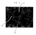
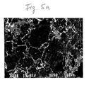
    • a main phase made of a Zr-Ni-Mn based alloy,
    • numerous cracks formed at the time when the rare earth element hydride is generated, and
    • a regenerated phase made of a rare earth element-Ni type alloy being exposed on the surfaces of the cracks.
    "Zr-Ni-Mn based alloy" refers to an alloy whose approximate formula is (Zr, Ti)(Ni, Mn, V)2.
    As used herein, "rare earth element(s)-Ni type alloy" (or, e.g., "La-Ni type alloy") refers to an alloy which may include small amounts of materials other than rare earth element and Ni, e.g., a suitable rare earth element(s)-Ni type alloy may consist of 71.0 - 78.6 % La, 21.2 - 28.8 % Ni, and < 0.4 % other materials.
    The reason the composition of the hydrogen occluding alloy according to the present invention is limited to the foregoing ranges will now be described.
    (a) Zr
    The Zr component forms the main phase in association with Ni and Mn to increase the amount of the hydrogen occluded as described above. When the Zr content is less than 25%, the desired amount of hydrogen cannot be occluded. Whereas, if the content exceeds 45%, the amount of hydrogen occluded by the alloy decreases. Therefore, the Zr content is determined to be 25% to 45%, preferably 25% to 40% and more preferably 30% to 37%.
    (b) Ti
    The Ti component, dissolved in the main phase set forth above, lowers the equilibrium pressure for dissociating hydrogen to a level lower than the atmospheric pressure at room temperature, for example, so that the component promotes the hydrogen absorption/desorption and increases the amount of hydrogen occluded. If the Ti content is less than 1%, the desired effect as set forth above cannot be achieved. on the other hand, when the content exceeds 12%, the equilibrium pressure for dissociating hydrogen is again raised to, for example, a level higher than the atmospheric pressure at room temperature. As a result, the hydrogen absorption/desorption decreases. Therefore, the Ti content is determined to be 1% to 12%, and preferably 4% to 12% and more preferably 5% to 10%.
    (c) Mn
    The Mn component forms the main phase made of the Zr-Ni-Mn based alloy which occludes hydrogen as set forth above. When the Mn content is less than 10%, the main phase does not achieve the desired hydrogen-occluding capacity, whereas an Mn content over 20% suppresses the hydrogen absorption/desorption capability. Therefore, the content is determined to be 10% to 20%, and preferably, 14% to 18%.
    (d) V
    The V component dissolved in the main phase stabilizes absorption/desorption of hydrogen by adjusting the equilibrium pressure for dissociating hydrogen and increases the quantity of occluded hydrogen. If the V content is less than 2%, the desired effect set forth above cannot be achieved, whereas a content exceeding 12% does not bring about further improvement in such effects. Therefore, the content is determined to be 2% to 12%, and preferably 2% to 8% and more preferably 3% to 6%.
    (e) Rare earth element(s)
    This component(s) is/are essential for the formation of the regenerated phase made of the rare earth element-Ni type alloy which dissociates to absorb atmospheric hydrogen at a higher rate than that of the main phase and desorbs to recombine hydrogen to the atmosphere, as described above. If the content is less than 0.5%, the resulting amount of the regenerated phase made of the rare earth element-Ni type alloy is too small to maintain such functions. On the other hand, since a content exceeding 5% causes an excessive amount of the phase made of the regenerated rare earth element-Ni type alloy, the amount of hydrogen that can be occluded into the overall alloy decreases unsatisfactorily. Therefore, the content is determined to be 0.5% to 5% and preferably 2% to 4%.
    To enhance the effects of the rare earth element-Ni type alloy and the regenerated phase made of the rare earth element-Ni type alloy, it is preferred that the rare earth element comprises La and/or Ce, preferably consists of 50% or more of La and/or Ce, and more preferably, consists essentially of La and/or Ce.
    (f) Hf
    The Hf content (Hf is optional), when present, which forms a main phase made of a Zr-Ni-Mn based alloy along with the Zr component, enhances the effects set forth above. If the Hf content is less than 0.1%, the desired effect cannot be obtained, whereas if the content exceeds 4%, the above function of the Zr content is impaired. Therefore, when Hf is present, the content is determined to be 0.1% to 4%, preferably 0.1% to 2% and more preferably 1% to 1.7%.
    (g) Ni
    If the Ni content is less than 25%, rare earth element-Ni type alloy and the regenerated rare earth element-Ni type alloy cannot be sufficiently formed. Since such alloy does not exhibit a desired hydrogen discharge rate and initial activation, the content is determined to be at least 25%.
    The hydrogen occluding alloy in accordance with the present invention can be used as powder having a predetermined particle size by any conventional mechanical pulverization. In addition, the alloy can also be pulverized by a hydrogenation process in which hydrogen is absorbed at a given temperature ranging from 10 to 200 °C and desorbed by evacuation.
    Brief Description of the Figures
  • Fig. 1 is an enlarged schematic view of the structure of hydrogen occluding alloys 1 to 13, 33 to 53, 93 and 94, with no Hf, in accordance with the present invention;
  • Fig. 2 is an enlarged schematic view of the structure of hydrogen occluding alloys 14 to 32, 54 to 92, 95 and 96, with Hf, in accordance with the present invention;
  • Fig. 3 is an enlarged schematic view of the structure of a conventional hydrogen occluding alloy;
  • Fig. 4 is a schematic view of the apparatus used for measuring the hydrogen absorption/desorption rates of the hydrogen occluding alloy; and
  • Fig. 5 is an SEM picture of a hydrogen occluding alloy in accordance with embodiment (a), discussed above. Fig. 5a is an original photograph of the SEM picture.
  • Detailed Description of Preferred Embodiments
    The hydrogen occluding alloy in accordance with the present invention will now be described in further detail by an embodiment.
    In an ordinary high-frequency induction melting furnace, Ni, Zr, Ti, Mn, V, La, Ce, Cr and Hf, as well as misch metal, each having a purity higher than 99.9%, are melted in an Ar atmosphere to prepare alloys having compositions as shown in Tables 1, 3, 5, 7, 9, 11, 13 and 15. Each alloy is cast in a water-cooled copper casting mold to be formed into an ingot. Each of the ingots is heated for homogenization under vacuum at a predetermined temperature within the range of from 900°C to 1100°C for 20 hours.
    After the ingot is maintained at room temperature for 1 hour in a hydrogen atmosphere of a pressure in the range of from 1 to 1.2 atm., it is heated to a predetermined temperature within a range of from 600°C to 700°C and subjected to a hydrogenation treatment at the predetermined temperature for 30 minutes, so that the phase made of the rare earth element-Ni type alloy, which distributes along the grain boundary of the main phase made of the Zr-Ni-Mn based alloy, is converted into the hydride product phase mainly including rare earth element hydride and the rare earth element-Ni type alloy, where numerous cracks start from the hydride product phase. While holding the hydrogenation temperature set forth above, the ingot is subjected to dehydrogenation while evacuating until reaching a vacuum of 10-5 Torr, so that the phase made of the rare earth element-Ni type alloy is regenerated from the hydride product phase, Since the product is fluidized during the dehydrogenation process, the phase made of the regenerated rare earth element-Ni type alloy distributes expansively along numerous cracks as shown in Fig. 1 and 2. In such a way, hydrogen occluding alloys 1 to 92 in accordance with the present invention (hereinafter called "alloys of the present invention") are prepared. Alloys 93-96 are prepared in a similar way, except that after the hydrogenation step, they are cooled.
    For comparison, comparative hydrogen occluding alloys having compositions as shown in Tables 3, 5, 9 and 15 are prepared under the same conditions as those described above, except that the hydrogenation and dehydrogenation processes following the homogenizing heat treatment are omitted.
    The comparative alloy has a structure consisting of a matrix phase 21 made of a Zr-Ni-Mn based alloy and a dispersed phase 23 made of an La-Ni type alloy and distributed along the grain boundary 22 of the matrix phase, as shown in Fig. 3.
    Then, the hydrogen absorption rate and the hydrogen desorption rate of each of the alloys 1 to 96 of the present invention and the comparative alloys are measured in accordance with JIS·H7202 "Method for Measuring Hydrogenation Rate of Hydrogen Occluding Alloy".
    Prior to the measurement, alloys 1 to 96 of the present invention and the comparative alloys are respectively enclosed in a pressure container and subjected to hydrogenation pulverization including hydrogen absorption in a hydrogen atmosphere of 8 atm. at 200 °c for one hour, and the hydrogen desorption by evacuation to prepare powders having a particle size of 200 mesh or less.
    First, the hydrogen-absorption rate is, as illustrated in a schematic view in Fig. 4, measured as follows:
  • (a) Powder is enclosed in a container 41 immersed in a (oil or water) bath 42, then a valve Vb is closed and valves Va and Vc are opened while maintaining the temperature in the bath at 200°C in order to introduce pressurized hydrogen into the system from a hydrogen cylinder 43. When the pressure in the system reaches 30 atm., the valve Va is closed and the system is then allowed to stand until the pressure in the system decreases to a predetermined level (until the hydrogen absorption is completed). Thus, the powder is initially activated.
  • (b) After the pressure in the system decreases to a predetermined level (around 20 atm.), the valve Vb is opened, followed by lowering the pressure in the system to 10-2 Torr by a vacuum pump 44. The bath temperature is lowered to 20°C and the valves Vb and Vc are closed and the valve Va is opened to introduce hydrogen into the system, except for the container. When the pressure is raised to 30 atm., the valve Va is closed and the valve Vc is opened. In such a state, the pressure drop in the system with respect to time is measured. The quantity of occluded hydrogen at the point when the quantity of hydrogen occluded by powder reaches 80%, and time taken to the foregoing moment are obtained from the pressure-drop curve so that (the quantity of occluded hydrogen when the occlusion of 80 % is realized)/(the time taken to realize the occlusion of 80%) is calculated. The thus-obtained value is defined as the hydrogen absorption rate.
  • The hydrogen desorption rate is determined by the following procedure: The bath is maintained at a temperature of, for example, 120°C, appropriate for hydrogen desorption within a range of from 100°C to 300°C in a state in which the measurement of the hydrogen absorption rate has been completed, that is, in a state in which the valves Va and Vb are closed, the valve Vc is opened, and the pressure in the system reaches a predetermined level (usually around 20 atm.). Then, the valve Vb is opened and the valve Vc is closed, and in the foregoing state, the pressure in the system, except for the container 41, is lowered to 10-2 Torr. Then, the valve Vb is closed and the valve Vc is opened, and in this state, the pressure rise in the system with respect to time is measured. The quantity of desorbed hydrogen at the point when the quantity of hydrogen desorbed from powder reaches 80%, and time taken to the foregoing moment are obtained from the pressure-rise curve so that (the quantity of desorbed hydrogen when the desorption of 80% is realized)/(the time taken to realize the desorption of 80%) is calculated. The thus-obtained value is defined as the hydrogen desorption rate. The results are shown in Tables 2, 4, 6, 8, 10, 12, 14 and 16.
    For the purpose of evaluating the initial activation of alloys 1 to 96 of the present invention and conventional alloy, each alloy is used for an active material of a battery in the powder state, and the battery is subjected to repeated charge/discharge cycles until the battery shows a maximum discharge capacity as shown below in detail. The initial activation is taken as the number of charge/discharge cycles at which the discharge capacity corresponds to 95% of the maximum discharge capacity.
    The conventional alloy is roughly crushed to form coarse particles of 2 mm or less in diameter with a jaw crusher, and each of alloys 1 to 96 of the present invention and roughly crushed conventional alloy is finely ground to 200 mesh or less with a ball mill. After water, polytetrafluoroethylene (PTFE) as a binder and carboxymethyl cellulose (CMC) as a thickener are added into each powder to obtain a paste, the paste is loaded on a commercial foamed nickel plate having a porosity of 95%. The foamed nickel plate is dried, pressed, and shaped into a cut plate of 30 by 40 mm having a thickness of 0.40 to 0.43 mm. The amount of the loaded active material is approximately 1.8 g. A nickel thin plate as a lead is welded at a side of the cut plate to form a negative electrode. On the other hand, a positive electrode is formed by preparing a paste from Ni(OH)2 as an active material, water, polytetrafluoroethylene (PTFE) as a binder and carboxymethyl cellulose (CMC) as a thickener; loading the paste on the foamed nickel plate; drying, pressing and shaping the foamed nickel plate into a cut plate of 30 by 40 mm having a thickness of 0.71 to 0.73 mm; and welding the nickel thin plate at a side of the cut plate. The positive electrodes are provided at both sides of the negative electrodes through separators made of a polypropylene/polyethylene copolymer, and, protecting plates made of polyvinyl chloride are integrated therewith at both sides of the positive electrodes to prevent the omission of the active material from the outside of the positive electrodes.
    • 1 The battery, whose electrode has component composition shown in samples 1-13, is fabricated by inserting thus-obtained integrated electrodes into a cell made of polyvinyl chloride and pouring a 35% KOH aqueous solution, as an electrolyte solution, into the cell. The resultant battery is subjected to charge/discharge cycles under conditions of a charging rate of 0.20 C, a discharging rate of 0.20 C and a quantity of charged capacity corresponding to 135% of the negative electrode capacity. The charge/discharge cycles are repeated until the battery exhibits the maximum discharge capacity, in which one cycle of charge and discharge is counted as one charge/discharge.Tables 2 and 4 show the maximum discharge capacity obtained by the procedure set forth above, as well as the number of charge/discharge cycles as a measure evaluating the initial activation, at which the discharge capacity is 95% of the maximum discharge capacity.
    • 2 The battery, whose electrodes have component compositions shown in samples 14-32, is fabricated by inserting thus-obtained integrated electrodes into a cell made of polyvinyl chloride and pouring a 35% KOH aqueous solution, as an electrolyte solution, into the cell. The resulting battery is subjected to charge/discharge cycles under conditions of a charging rate of 0.20 C a discharging rate of 0.22 C, and a quantity of charged capacity corresponding to 135% of the negative electrode capacity. The charge/discharge cycles are repeated until the battery exhibits the maximum discharge capacity, in which one cycle of charge and discharge is counted as one charge/discharge.Tables 4 and 6 show the maximum discharge capacity obtained by the procedure set forth above, as well as the number of charge/discharge cycles as a measure evaluating the initial activation, at which the discharge capacity is 95% of the maximum discharge capacity.
    • 3 The battery, whose electrodes have component compositions shown in samples 33-92, is fabricated by inserting thus-obtained integrated electrodes into a cell made of polyvinyl chloride and pouring a 30% KOH aqueous solution, as an electrolyte solution, into the cell. The resulting battery is subjected to charge/discharge cycles under conditions of a charging rate of 0.15 C, a discharging rate of 0.15 C, and a quantity of charged capacity corresponding to 135% of the negative electrode capacity. The charge/discharge cycles are repeated until the battery exhibits the maximum discharge capacity, in which one cycle of charge and discharge is counted as one charge/discharge.Tables 6, 8, 10, 12, 14 and 16 show the maximum discharge capacity obtained by the procedure set forth above, as well as the number of charge/discharge cycles as a measure evaluating the initial activation, at which the discharge capacity is 95% of the maximum discharge capacity.
    • 4 The battery, whose electrodes have component compositions shown in samples 93-96, is fabricated by inserting thus-obtained integrated electrodes into a cell made of polyvinyl chloride and pouring a 30% KOH aqueous solution, as an electrolyte solution, into the cell.
    The resulting battery is subjected to charge/discharge cycles under conditions of a charging rate of 0.15 C, a discharging rate of 0.15 C, and a quantity of charged capacity corresponding to 135% of the negative electrode capacity. The charge/discharge cycles are repeated until the battery exhibits the maximum discharge capacity, in which one cycle of charge and discharge is counted as one charge/discharge.
    Table 16 shows the maximum discharge capacity obtained by the procedure set forth .above, as well as the number of charge/discharge cycles as a measure evaluating the initial activation, at which the discharge capacity is 95% of the maximum discharge capacity.
    Results in Tables 2, 4, 6, 8, 10, 12, 14 and 16 evidently demonstrate that each of alloys 1 to 96 of the present invention exhibits higher hydrogen absorption and desorption rates by the effect of the regenerated phase made of the rare earth element-Ni type alloy having a wide effective area since the phase distributes expansively while flowing along numerous cracks, compared with the conventional alloy having the phase made of the La-Ni type alloy dispersively distributed along grains, resulting in an improvement in the initial activity.
    As described above, since the hydrogen occluding alloy in accordance with the present invention exhibits significantly high hydrogen absorption/desorption rates, and excellent initial activity, it significantly contributes to the achievement of high output, high performance, and energy savings in various mechanical apparatuses.
    Figure 00220001
    Figure 00230001
    Figure 00240001
    Figure 00250001
    Figure 00260001
    Figure 00270001
    Figure 00280001
    Figure 00290001
    Figure 00300001
    Figure 00310001
    Figure 00320001
    Figure 00330001
    Figure 00340001
    Figure 00350001
    Figure 00360001
    Figure 00370001

    Claims (10)

    1. A hydrogen occluding alloy having a composition comprising by wt%:
      25 to 45 % of Zr,
      1 to 12 % of Ti,
      10 to 20 % of Mn,
      2 to 12 % of V,
      0,5 to 5 % of at least one rare earth element,
      unavoidable impurities,
      optionally 0,1 to 4 % of Hf
      and balance Ni, wherein the amount of Ni is at least 25 %,
      having a structure comprising main phase made of Zr-Ni-Mn based alloy and having cracks and a phase made of a regenerated rare earth element-Ni type alloy expansively distributed along said cracks.
    2. A hydrogen occluding alloy as recited in claim 1, wherein said composition comprises by wt%:
      25 to 40% of Zr,   4 to 12% of Ti,
      10 to 20% of Mn,   2 to 8% of V,
      0.5 to 5% of at least one rare earth element,
      unavoidable impurities, and at least 25% of Ni
    3. A hydrogen occluding alloy as recited in claim 1, wherein said composition consists essentially of, by wt%:
      30 to 37% of Zr,   5 to 10% of Ti,
      14 to 18% of Mn,   3 to 6% of V,
      2 to 4 % of La and/or Ce,
      unavoidable impurities,
      and at least 25% of Ni.
    4. A hydrogen occluding alloy as recited in claims 1, 2 or 3, wherein said composition further comprises 0.1 - 2.0 weight percent of Hf.
    5. A hydrogen occluding alloy as recited in claims 1, 2 or 3, wherein said composition further comprises 1.0 - 1.7 weight percent of Hf.
    6. A hydrogen occluding alloy as recited in claims 1 to 5, wherein said at least one rare earth element comprises La and/or Ce.
    7. A process for producing a hydrogen occluding alloy, comprising:
      (a) preparing an alloy ingot having a composition comprising, by weight:
      25 to 45% of Zr,   1 to 12% of Ti,
      10 to 20% of Mn,   2 to 12% of V,
      0.5% to 5% of at least one rare earth element,
      unavoidable impurities
         and at least 25% of Ni,
      (b) homogenizing said ingot in a non-oxidizing atmosphere,
      (c) hydrogenating said ingot in a hydrogen atmosphere at a temperature in the range of from 400°C to 700°C, and
      (d) dehydrogenating said ingot at a temperature in the range of from 600°C to 700°C.
    8. A process as recited in claim 7, wherein said composition is a composition as claimed in any of claims 2 to 6.
    9. A hydrogen occluding alloy formed according to a process comprising:
      (a) preparing an alloy ingot having a composition comprising, by weight:
      25 to 45% of Zr,   1 to 12% of Ti,
      10 to 20% of Mn,   2 to 12% of V,
      0.5% to 5% of at least one rare earth element,
      unavoidable impurities,
         and at least 25% of Ni,
      (b) homogenizing said ingot in a non-oxidizing atmosphere to provide a structure including Zr-Ni-Mn based alloy and rare earth-Ni type alloy,
      (c) hydrogenating said ingot in a hydrogen atmosphere at a temperature in the range of from 400°C to 700°C, thereby forming cracks in said Zr-Ni-Mn based alloy and converting at least some of said rare earth-Ni type alloy to rare earth element hydride, and
      (d) dehydrogenating said ingot at a temperature in the range of from 600°C to 700°C, thereby regenerating and fluidizing a rare earth element-Ni type alloy which flows along said cracks.
    10. An electrode for a Ni-hydrogen battery, said electrode comprising a hydrogen occluding alloy as recited in any of claims 1 to 6, and 9.
    EP96113226A 1995-08-21 1996-08-17 Hydrogen occluding alloy and electrode made of the alloy Expired - Lifetime EP0761833B1 (en)

    Applications Claiming Priority (12)

    Application Number Priority Date Filing Date Title
    JP23477195 1995-08-21
    JP234771/95 1995-08-21
    JP23477195 1995-08-21
    JP27754495 1995-10-25
    JP27754495 1995-10-25
    JP277544/95 1995-10-25
    JP8105096A JPH09176778A (en) 1995-10-25 1996-04-25 Hydrogen storage alloy
    JP10509296 1996-04-25
    JP105092/96 1996-04-25
    JP10509296A JPH09118948A (en) 1995-08-21 1996-04-25 Hydrogen storage alloy
    JP10509696 1996-04-25
    JP105096/96 1996-04-25

    Publications (2)

    Publication Number Publication Date
    EP0761833A1 EP0761833A1 (en) 1997-03-12
    EP0761833B1 true EP0761833B1 (en) 2001-12-12

    Family

    ID=27469287

    Family Applications (1)

    Application Number Title Priority Date Filing Date
    EP96113226A Expired - Lifetime EP0761833B1 (en) 1995-08-21 1996-08-17 Hydrogen occluding alloy and electrode made of the alloy

    Country Status (4)

    Country Link
    EP (1) EP0761833B1 (en)
    KR (1) KR970070220A (en)
    CN (1) CN1151616A (en)
    DE (1) DE69617837T2 (en)

    Families Citing this family (2)

    * Cited by examiner, † Cited by third party
    Publication number Priority date Publication date Assignee Title
    WO2002014567A1 (en) * 2000-08-16 2002-02-21 Ovonic Battery Company, Inc. High power nickel-metal hydride batteries and high power alloys/electrodes for use therein
    CN105071857B (en) * 2015-06-30 2019-01-22 武汉光迅科技股份有限公司 Optical transmission system is relayed on cascade multi-span tower

    Family Cites Families (5)

    * Cited by examiner, † Cited by third party
    Publication number Priority date Publication date Assignee Title
    JPS60241652A (en) * 1984-05-16 1985-11-30 Matsushita Electric Ind Co Ltd Electrochemical electrode employing metal hydride
    KR920010422B1 (en) * 1987-05-15 1992-11-27 마쯔시다덴기산교 가부시기가이샤 Electrode and method of storage hidrogine
    JPH04188805A (en) * 1990-11-22 1992-07-07 Seiko Epson Corp Manufacture of rare-earth bonded magnet
    JPH06283169A (en) * 1993-03-29 1994-10-07 Hitachi Chem Co Ltd Sealed type secondary battery
    JPH06306413A (en) * 1993-04-28 1994-11-01 Daido Steel Co Ltd Production of hydrogen storage alloy powder

    Also Published As

    Publication number Publication date
    DE69617837D1 (en) 2002-01-24
    KR970070220A (en) 1997-11-07
    DE69617837T2 (en) 2002-04-11
    EP0761833A1 (en) 1997-03-12
    CN1151616A (en) 1997-06-11

    Similar Documents

    Publication Publication Date Title
    JP3965209B2 (en) Low Co hydrogen storage alloy
    US5932369A (en) Hydrogen occluding alloy and electrode made of the alloy
    EP0806803B1 (en) Hydrogen occluding alloy, process for its preparation and electrode
    EP0753590B1 (en) Hydrogen occluding alloy and electrode made of the alloy
    EP0761833B1 (en) Hydrogen occluding alloy and electrode made of the alloy
    EP0969110A2 (en) Hydrogen occluding alloy
    US5951945A (en) Hydrogen occluding alloy and electrode made of the alloy
    US5810981A (en) Three phase hydrogen occluding alloy and electrode made of the alloy
    JPH1025528A (en) Hydrogen storage alloy
    JPH09176778A (en) Hydrogen storage alloy
    JP2002075347A (en) Hydrogen storage alloy
    JPH10195569A (en) Hydrogen storage alloy excellent in initial activity
    JPH09176777A (en) Hydrogen storage alloy
    JPH10152740A (en) Hydrogen storage alloy
    JPH0978167A (en) Hydrogen storage alloy
    JPH0959733A (en) Hydrogen storage alloy
    JPH0978176A (en) Hydrogen storage alloy
    JPH10195575A (en) Hydrogen storage alloy excellent in initial activity
    JPH0987784A (en) Hydrogen storage alloy
    JPH10195584A (en) Hydrogen storage alloy excellent in initial activity
    JPH09176776A (en) Hydrogen storage alloy
    JPH09176775A (en) Hydrogen storage alloy
    JPH09118948A (en) Hydrogen storage alloy
    JPH10195572A (en) Hydrogen storage alloy excellent in initial activity
    JPH0987785A (en) Hydrogen storage alloy

    Legal Events

    Date Code Title Description
    PUAI Public reference made under article 153(3) epc to a published international application that has entered the european phase

    Free format text: ORIGINAL CODE: 0009012

    AK Designated contracting states

    Kind code of ref document: A1

    Designated state(s): CH DE FR GB IT LI NL SE

    17P Request for examination filed

    Effective date: 19970814

    17Q First examination report despatched

    Effective date: 19980819

    GRAG Despatch of communication of intention to grant

    Free format text: ORIGINAL CODE: EPIDOS AGRA

    GRAG Despatch of communication of intention to grant

    Free format text: ORIGINAL CODE: EPIDOS AGRA

    GRAG Despatch of communication of intention to grant

    Free format text: ORIGINAL CODE: EPIDOS AGRA

    GRAH Despatch of communication of intention to grant a patent

    Free format text: ORIGINAL CODE: EPIDOS IGRA

    GRAH Despatch of communication of intention to grant a patent

    Free format text: ORIGINAL CODE: EPIDOS IGRA

    GRAA (expected) grant

    Free format text: ORIGINAL CODE: 0009210

    AK Designated contracting states

    Kind code of ref document: B1

    Designated state(s): CH DE FR GB IT LI NL SE

    PG25 Lapsed in a contracting state [announced via postgrant information from national office to epo]

    Ref country code: NL

    Free format text: LAPSE BECAUSE OF FAILURE TO SUBMIT A TRANSLATION OF THE DESCRIPTION OR TO PAY THE FEE WITHIN THE PRESCRIBED TIME-LIMIT

    Effective date: 20011212

    Ref country code: LI

    Free format text: LAPSE BECAUSE OF FAILURE TO SUBMIT A TRANSLATION OF THE DESCRIPTION OR TO PAY THE FEE WITHIN THE PRESCRIBED TIME-LIMIT

    Effective date: 20011212

    Ref country code: IT

    Free format text: LAPSE BECAUSE OF FAILURE TO SUBMIT A TRANSLATION OF THE DESCRIPTION OR TO PAY THE FEE WITHIN THE PRE;WARNING: LAPSES OF ITALIAN PATENTS WITH EFFECTIVE DATE BEFORE 2007 MAY HAVE OCCURRED AT ANY TIME BEFORE 2007. THE CORRECT EFFECTIVE DATE MAY BE DIFFERENT FROM THE ONE RECORDED.SCRIBED TIME-LIMIT

    Effective date: 20011212

    Ref country code: CH

    Free format text: LAPSE BECAUSE OF FAILURE TO SUBMIT A TRANSLATION OF THE DESCRIPTION OR TO PAY THE FEE WITHIN THE PRESCRIBED TIME-LIMIT

    Effective date: 20011212

    REG Reference to a national code

    Ref country code: CH

    Ref legal event code: EP

    REG Reference to a national code

    Ref country code: GB

    Ref legal event code: IF02

    REF Corresponds to:

    Ref document number: 69617837

    Country of ref document: DE

    Date of ref document: 20020124

    PG25 Lapsed in a contracting state [announced via postgrant information from national office to epo]

    Ref country code: SE

    Free format text: LAPSE BECAUSE OF FAILURE TO SUBMIT A TRANSLATION OF THE DESCRIPTION OR TO PAY THE FEE WITHIN THE PRESCRIBED TIME-LIMIT

    Effective date: 20020312

    NLV1 Nl: lapsed or annulled due to failure to fulfill the requirements of art. 29p and 29m of the patents act
    REG Reference to a national code

    Ref country code: CH

    Ref legal event code: PL

    PGFP Annual fee paid to national office [announced via postgrant information from national office to epo]

    Ref country code: DE

    Payment date: 20020809

    Year of fee payment: 7

    PGFP Annual fee paid to national office [announced via postgrant information from national office to epo]

    Ref country code: FR

    Payment date: 20020812

    Year of fee payment: 7

    PG25 Lapsed in a contracting state [announced via postgrant information from national office to epo]

    Ref country code: GB

    Free format text: LAPSE BECAUSE OF NON-PAYMENT OF DUE FEES

    Effective date: 20020817

    PLBE No opposition filed within time limit

    Free format text: ORIGINAL CODE: 0009261

    STAA Information on the status of an ep patent application or granted ep patent

    Free format text: STATUS: NO OPPOSITION FILED WITHIN TIME LIMIT

    26N No opposition filed
    GBPC Gb: european patent ceased through non-payment of renewal fee

    Effective date: 20020817

    NLV1 Nl: lapsed or annulled due to failure to fulfill the requirements of art. 29p and 29m of the patents act
    PG25 Lapsed in a contracting state [announced via postgrant information from national office to epo]

    Ref country code: DE

    Free format text: LAPSE BECAUSE OF NON-PAYMENT OF DUE FEES

    Effective date: 20040302

    PG25 Lapsed in a contracting state [announced via postgrant information from national office to epo]

    Ref country code: FR

    Free format text: LAPSE BECAUSE OF NON-PAYMENT OF DUE FEES

    Effective date: 20040430

    REG Reference to a national code

    Ref country code: FR

    Ref legal event code: ST