EP0761432B2 - Damping unit for an offset printing machine - Google Patents
Damping unit for an offset printing machine Download PDFInfo
- Publication number
- EP0761432B2 EP0761432B2 EP96110864A EP96110864A EP0761432B2 EP 0761432 B2 EP0761432 B2 EP 0761432B2 EP 96110864 A EP96110864 A EP 96110864A EP 96110864 A EP96110864 A EP 96110864A EP 0761432 B2 EP0761432 B2 EP 0761432B2
- Authority
- EP
- European Patent Office
- Prior art keywords
- roller
- damping
- dampening
- unit
- agent
- Prior art date
- Legal status (The legal status is an assumption and is not a legal conclusion. Google has not performed a legal analysis and makes no representation as to the accuracy of the status listed.)
- Expired - Lifetime
Links
- 238000007645 offset printing Methods 0.000 title claims abstract description 4
- 238000013016 damping Methods 0.000 title claims description 33
- 238000007639 printing Methods 0.000 claims abstract description 18
- 239000003795 chemical substances by application Substances 0.000 claims abstract 15
- 230000002093 peripheral effect Effects 0.000 claims description 10
- 238000000926 separation method Methods 0.000 claims description 3
- VYZAMTAEIAYCRO-UHFFFAOYSA-N Chromium Chemical compound [Cr] VYZAMTAEIAYCRO-UHFFFAOYSA-N 0.000 claims description 2
- 229910052710 silicon Inorganic materials 0.000 claims description 2
- 239000010703 silicon Substances 0.000 claims description 2
- 229910001220 stainless steel Inorganic materials 0.000 claims description 2
- 239000010935 stainless steel Substances 0.000 claims description 2
- 238000011144 upstream manufacturing Methods 0.000 claims description 2
- 229910000669 Chrome steel Inorganic materials 0.000 claims 1
- 239000000919 ceramic Substances 0.000 claims 1
- 239000000463 material Substances 0.000 claims 1
- 230000003534 oscillatory effect Effects 0.000 claims 1
- 239000000976 ink Substances 0.000 abstract 1
- 238000012549 training Methods 0.000 description 5
- XUIMIQQOPSSXEZ-UHFFFAOYSA-N Silicon Chemical compound [Si] XUIMIQQOPSSXEZ-UHFFFAOYSA-N 0.000 description 2
- 239000011248 coating agent Substances 0.000 description 2
- 238000000576 coating method Methods 0.000 description 2
- 238000011161 development Methods 0.000 description 2
- 230000018109 developmental process Effects 0.000 description 2
- 239000000203 mixture Substances 0.000 description 2
- XLYOFNOQVPJJNP-UHFFFAOYSA-N water Substances O XLYOFNOQVPJJNP-UHFFFAOYSA-N 0.000 description 2
- LFQSCWFLJHTTHZ-UHFFFAOYSA-N Ethanol Chemical compound CCO LFQSCWFLJHTTHZ-UHFFFAOYSA-N 0.000 description 1
- 229910010293 ceramic material Inorganic materials 0.000 description 1
- 230000008878 coupling Effects 0.000 description 1
- 238000010168 coupling process Methods 0.000 description 1
- 238000005859 coupling reaction Methods 0.000 description 1
- 230000006735 deficit Effects 0.000 description 1
- 230000000694 effects Effects 0.000 description 1
- 230000001771 impaired effect Effects 0.000 description 1
- 238000000034 method Methods 0.000 description 1
- 239000003973 paint Substances 0.000 description 1
- 239000002245 particle Substances 0.000 description 1
- 238000005406 washing Methods 0.000 description 1
- 239000002699 waste material Substances 0.000 description 1
Images

Classifications
-
- B—PERFORMING OPERATIONS; TRANSPORTING
- B41—PRINTING; LINING MACHINES; TYPEWRITERS; STAMPS
- B41F—PRINTING MACHINES OR PRESSES
- B41F7/00—Rotary lithographic machines
- B41F7/20—Details
- B41F7/24—Damping devices
- B41F7/26—Damping devices using transfer rollers
Definitions
- the invention relates to a dampening system for a Offset printing machine with an inking unit and a plate cylinder in a printing form Active connection is established.
- a dampening unit of this type is known from DE 3 416 845 A1 known. Then there is a dampening system in the essentially from a feeder for the Fountain solution, a device for dosing the Fountain solution film and an applicator roller, the Transfers dampening solution film to a platter cylinder and coupled with the neighboring inking unit or also can be operated separately.
- the dampening roller can be different to the plate cylinder Have peripheral speed so that a for example, wiping effect removing foreign particles arises.
- a dampening system is for Rotary printing presses with a duct roller, one Dampening roller and an intermediate and applicator roller known.
- the intermediate and applicator roller is after an inking roller at the point of contact with the plate cylinder subordinate as contact point, the one Buffer roller absorbing dampening solution as further contact point is additionally subordinate.
- the buffer roller should temporarily store a dampening solution excess and gradually to the intermediate and applicator roller hand back. The dampening solution excess results from the pre-dampening of the intermediate and Applicator roller fed, but from the plate cylinder channel not included, supply of dampening solution.
- EP-A-0 450 155 is a control circuit for a printing unit of an offset sheet-fed printing machine known with a dampening system.
- the dampening roller of the dampening unit is removed from the plate cylinder turned off, pre-moistened and then in the pre-moistened state on the plate cylinder employed and this moistened. thereupon the inking rollers on the plate cylinder hired.
- This control circuit is designed to measure the amount Noticeably reduce waste sheets at the start of printing.
- the object of the invention is the print quality through an even, trouble-free dampening solution supply to improve the plate cylinder noticeably. Solved this is according to the invention through the training features of claims 1 to 4. Further developments result from the subclaims.
- the object of the invention is the print quality through an even, trouble-free dampening solution supply to improve the plate cylinder noticeably. Solved this is according to the invention through the training features of claim 1. Further developments result itself from the subclaims.
- dampening roller is after the contact point of Damping roller and plate cylinder of the dampening roller absorbing at least one dampening solution Assigned roller as rider roller.
- this rider roller can also be a additional dampening solution absorbing second roller (Tandem roller) adjacent, which also in Is in contact with the dampening roller.
- second roller Tedem roller
- the dampening solution absorbing (First and second) rollers mostly separate the fountain solution from the printing ink and lead the dampening solution in a different place in preferred reduced amount of the dampening roller again to.
- the ink / dampening solution mixture is on the dampening roller equalized as structure, so that the Dampening roller from the dampening solution supply device supplied dampening solution again and on transported the plate cylinder. Will this structure not completely destroyed, this leads to an unstable Dampening. Thanks to a dampening agent-friendly surface the rider roll or rider roll and subordinate Tandem roller thus finds a better one Exchange of residual water between the dampening roller, the rider roll and possibly the Tandem roller and again the dampening roller instead of. This creates a uniform surface structure on the dampening roller after contact with the rider roller or tandem roller if necessary.
- the dampening roller absorbing reduces the Stencil tendency (shadow-like markings) with the surface pressure as well as the one uneven Cord stripe that creates pressure. It was found, that in the present dampening system the dampening solution supply from the dampening roller is reduced can be reduced and the use of alcohol is reduced can be.
- the dampening system can Printing process coupled with the inking unit as well operated separately.
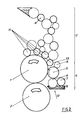
- a platter cylinder 1 stands with a dampening system 4 in operative connection.
- the inking unit 3 consists of several inking rollers 11, the ink to be fed Rollers (unspecified) are connected.
- the dampening unit 4 is - in the direction of rotation of the plate cylinder 1 considered - upstream of the inking unit 3 and in the present example consists of a dampening solution tank 8, a dampening device 6, a dampening device 7 and a dampening roller 5.
- the dampening solution tank 8 and dampening duct 6 form the Fountain solution supply device 12 and the dampening device 7 forms at the nip to the dampening roller 5 the already very thin dampening solution film out.
- the dampening roller 5 is one according to FIG.
- the roller 9 is after the contact point of Damping roller 5 / plate cylinder 1 of the dampening roller 5 downstream in their direction of rotation. She is in the present example, simultaneously as a bridge roller arranged by the roller 9 with the in the direction of rotation of the platter cylinder 1 first inking roller 11 des Inking unit 3 can be brought into contact. This switch position the roller 9, represented by a dashed line, becomes Coupling of the dampening unit 4 with the inking unit 3 for Washing the rollers used.
- the dampening roller 5 is still in the direction of rotation after the roller 9 another (second) dampening roller 10, referred to as a tandem roller.
- the rollers 9 and 10 are with an axially acting traversing drive coupled. Roller 9 and roller 10 have one Matt chrome surface coating.
- the dampening unit 4 is from Inking unit 3 at a separation point 13 (shown in FIG. 2) decoupled by the dampening roller 9 is separated from the first inking roller 11.
- the Dampening roller 5 is at a peripheral speed of the plate cylinder 1 same or deviating peripheral speed over a switchable positive drive operated. From the platter cylinder 1, the rotary movement is non-positive (by means of Friction) transferred to the inking rollers 11.
- the dampening rollers 9 and 10 can in a further training also a surface Stainless steel or from a dampening solution Ceramic material exist. So the roller surface also have a silicon metal or at least Silicon can be contained in the coating.
- the dampening solution-carrying second roller 10 is not assigned to the dampening roller 5.
- Fig. 2 Much more can the dampening unit 4 also in training gem. Fig. 2 are operated. After that is only one Dampening roller 9 of the dampening roller 5 assigned. This version is preferred in use when the dampening roller 5 little Fountain solution leads. The roller 9 then works perfectly sufficient in the dampening solution film on the Dampening roller 5 existing printing ink.
- the Dampening solution roller 9 to the dampening roller with different or the same peripheral speed operate.
- the downstream of the roller 9 Roller 10 can also be different or the same peripheral speed to the dampening roller 5 operated.
- the cylinder jacket length the rollers 9 and 10 is preferably identical to that Length of the circular arc of the channel of the plate cylinder 1.
- dampening agent-friendly Roller 9 forms after the contact point of dampening roller 5 / plate cylinder 1 on the dampening roller 5 a structure of dampening solution and color.
- the dampening agent-friendly Roller 9 including when using another dampening agent-friendly roller 10, this structure equalized.
- the surface structure of the ink / fountain solution mixture is on the dampening roller 5 equally distributed.
- the rollers 9 and 10 have a locking function compared to the paint on their dampening roller 5, which felt the return transport of printing ink into the Prevents dampening 4 and at the same time a stable Dampening solution dosage in the form of a very thin Guaranteed wet film.
Landscapes
- Engineering & Computer Science (AREA)
- Mechanical Engineering (AREA)
- Rotary Presses (AREA)
- Inking, Control Or Cleaning Of Printing Machines (AREA)
Abstract
Description
Die Erfindung betrifft ein Feuchtwerk für eine Offsetdruckmaschine, das mit einem Farbwerk und einem, eine Druckform tragenden Plattenzylinder in Wirkverbindung steht.The invention relates to a dampening system for a Offset printing machine with an inking unit and a plate cylinder in a printing form Active connection is established.
Ein Feuchtwerk dieser Art ist aus der DE 3 416 845 A1 bekannt. Danach besteht ein Feuchtwerk im wesentlichen aus einer Zuführeinrichtung für das Feuchtmittel, einer Einrichtung zur Dosierung des Feuchtmittelfilmes sowie einer Auftragwalze, die den Feuchtmittelfilm an einen Platterzylinder überträgt und mit dem benachbarten Farbwerk gekoppelt oder auch getrennt betrieben werden kann. Die Feuchtauftragwalze kann dabei zum Plattenzylinder eine unterschiedliche Umfangsgeschwindigkeit aufweisen, so daß ein beispielsweise Fremdpartikel beseitigender Wischeffekt entsteht.A dampening unit of this type is known from DE 3 416 845 A1 known. Then there is a dampening system in the essentially from a feeder for the Fountain solution, a device for dosing the Fountain solution film and an applicator roller, the Transfers dampening solution film to a platter cylinder and coupled with the neighboring inking unit or also can be operated separately. The dampening roller can be different to the plate cylinder Have peripheral speed so that a for example, wiping effect removing foreign particles arises.
Aus der DE 3 432 807 A1 in Verbindung mit der US-PS 4 724 764 ist ein weiterführendes Feuchtwerk bekannt. Neben wahlweise unterschiedlichen Umfangsgeschwindigkeiten von Plattenzylinder und Feuchtauftragwalze ist eine farbaufnehmende Walze als sogenannte Reiterwalze der Feuchtauftragwalze zugeordnet. Die farbaufnehmende Walze rotiert dabei mit einer zum Platterzylinder unterschiedlichen Umfangsgeschwindigkeit und kann mit einem benachbarten Farbwerk gekoppelt oder von diesem getrennt betrieben werden.From DE 3 432 807 A1 in connection with the U.S. Patent No. 4,724,764 is a continuing dampening system known. In addition to different peripheral speeds of plate cylinder and dampening roller is an ink receptive roller as so-called rider roller assigned to the dampening roller. The ink-absorbing roller rotates with it a different peripheral speed to the platter cylinder and can be with an adjacent Inking unit coupled or operated separately from this become.
Nachteilig bei diesen Ausführungen ist es, daß die auf der Feuchtauftragwalze sich ansammelnde Farbe in das Feuchtwerk geführt wird und damit das Farb-/Feuchtmittelgleichgewicht beeinträchtigt wird. Diese Beeinträchtigungen zeigen sich in Form von Schablonieren oder Kordstreifen (Schlieren).A disadvantage of these designs is that the one that accumulates on the dampening roller Ink is fed into the dampening system and thus the Color / fountain solution balance is impaired. These impairments are shown in the form of Stenciling or cord strips (streaks).
Gemäß GB-A- 20 35 903 ist ein Feuchtwerk für Rotationsdruckmaschinen mit einer Duktorwalze, einer Feuchtwerkwalze und einer Zwischen- und Auftragwalze bekannt. Der Zwischen-und Auftragwalze ist nach der Kontaktstelle mit dem Plattenzylinder eine Farbwerkswalze als Kontaktstelle nachgeordnet, der eine Feuchtmittel aufnehmende Pufferwalze als weitere Kontaktstelle zusätzlich nachgeordnet ist. Die Pufferwalze soll vorübergehend einen Feuchtmittelüberschuß speichern und allmählich an die Zwischen- und Auftragwalze zurückgeben. Der Feuchtmittelüberschuß resultiert aus dem vor Feuchtwerk der Zwischen- und Auftragwalze zugeführten, jedoch vom Plattenzylinderkanal nicht aufgenommenen, Angebot an Feuchtmittel.According to GB-A-20 35 903 a dampening system is for Rotary printing presses with a duct roller, one Dampening roller and an intermediate and applicator roller known. The intermediate and applicator roller is after an inking roller at the point of contact with the plate cylinder subordinate as contact point, the one Buffer roller absorbing dampening solution as further contact point is additionally subordinate. The buffer roller should temporarily store a dampening solution excess and gradually to the intermediate and applicator roller hand back. The dampening solution excess results from the pre-dampening of the intermediate and Applicator roller fed, but from the plate cylinder channel not included, supply of dampening solution.
Schließlich ist aus EP-A- 0 450 155 eine Steuerschaltung für ein Druckwerk einer Offset-Bogendruckmaschine mit einem Feuchtwerk bekannt. Die Feuchtauftragwalze des Feuchtwerkes wird vom Plattenzylinder kontaktlos abgestellt, vorgefeuchtet und anschließend im vorgefeuchteten Zustand an den Plattenzylinder angestellt und dieser befeuchtet. Daraufhin werden die Farbauftragwalzen an den Plattenzylinder angestellt. Diese Steuerschaltung soll die Menge an Makulaturbogen bei Druckbeginn spürbar reduzieren.Finally, EP-A-0 450 155 is a control circuit for a printing unit of an offset sheet-fed printing machine known with a dampening system. The The dampening roller of the dampening unit is removed from the plate cylinder turned off, pre-moistened and then in the pre-moistened state on the plate cylinder employed and this moistened. thereupon the inking rollers on the plate cylinder hired. This control circuit is designed to measure the amount Noticeably reduce waste sheets at the start of printing.
Aufgabe der Erfindung ist es, die Druckqualität
durch eine gleichmäßige, störungsfreie Feuchtmittelzufuhr
zum Plattenzylinder spürbar zu verbessern. Gelöst
wird dies erfindungsgemäß durch die Ausbildungsmerkmale
der Patentansprüche 1 bis 4. Weiterbildungen
ergeben sich aus den Unteransprüchen.The object of the invention is the print quality
through an even, trouble-free dampening solution supply
to improve the plate cylinder noticeably. Solved
this is according to the invention through the training features
of
Aufgabe der Erfindung ist es, die Druckqualität
durch eine gleichmäßige, störungsfreie Feuchtmittelzufuhr
zum Plattenzylinder spürbar zu verbessern. Gelöst
wird dies erfindungsgemäß durch die Ausbildungsmerkmale
des Patentanspruches 1. Weiterbildungen ergeben
sich aus den Unteransprüchen.The object of the invention is the print quality
through an even, trouble-free dampening solution supply
to improve the plate cylinder noticeably. Solved
this is according to the invention through the training features
of
In einem Feuchtwerk mit mindestens einer Feuchtauftragwalze ist nach der Kontaktstelle von Feuchtauftragwalze und Plattenzylinder der Feuchtauftragwalze mindestens eine Feuchtmittel aufnehmende Walze als Reiterwalze zugeordnet. In einer bevorzugten Weiterbildung kann diese Reiterwalze auch eine zusätzliche Feuchtmittel aufnehmende zweite Walze (Tandemwalze) benachbart aufweisen, die ebenfalls in Kontakt mit der Feuchtauftragwalze ist. Nach der Kontaktstelle von Feuchtauftragwalze/Plattenzylinder bildet sich eine Sujet bedingte Struktur von Wasser und Farbe auf der Feuchtauftragwalze aus. Die Feuchtmittel aufnehmenden (erste und zweite) Walzen trennen überwiegend das Feuchtmittel von der Druckfarbe und führen das Feuchtmittel an veränderter Stelle in bevorzugt reduzierter Menge wieder der Feuchtauftragwalze zu. Das Farb-/Feuchtmittelgemisch wird auf der Feuchtauftragwalze als Struktur egalisiert, derart daß die Feuchtauftragwalze von der Feuchtmittelzuführeinrichtung zugeführtes Feuchtmittel erneut aufnimmt und an den Plattenzylinder transportiert. Wird diese Struktur nicht vollständig zerstört, führt dies zu einer instabilen Feuchtung. Durch eine feuchtmittelfreundliche Oberfläche der Reiterwalze bzw. von Reiterwalze und nachgeordneter Tandemwalze findet somit ein besserer Austausch von Sujetrestwasser zwischen der Feuchtauftragwalze, der Reiterwalze und gegebenenfalls der Tandemwalze und wiederum der Feuchtauftragwalze statt. Dadurch entsteht eine gleichmäßige Oberflächenstruktur auf der Feuchtauftragwalze nach dem Kontakt mit der Reiterwalze bzw. gegebenenfalls Tandemwalze. Die Feuchtmittel aufnehmenden Walzen verringern die Schablonierneigung (schattenartige Markierungen) beim Flächendruck sowie die einen ungleichmäßigen Druck bewirkenden Kordstreifen. Es wurde gefunden, daß beim erfindungsgemäß vorliegenden Feuchtwerk die Feuchtmittelzufuhr vom Feuchtduktor her verringert werden kann und auch der Einsatz von Alkohol reduziert werden kann. Das Feuchtwerk kann dabei im Druckprozeß mit dem Farbwerk gekoppelt als auch getrennt betrieben werden.In a dampening system with at least one The dampening roller is after the contact point of Damping roller and plate cylinder of the dampening roller absorbing at least one dampening solution Assigned roller as rider roller. In a preferred one Further training, this rider roller can also be a additional dampening solution absorbing second roller (Tandem roller) adjacent, which also in Is in contact with the dampening roller. After the contact point of dampening roller / plate cylinder a subject-related structure of water and color on the dampening roller. The dampening solution absorbing (First and second) rollers mostly separate the fountain solution from the printing ink and lead the dampening solution in a different place in preferred reduced amount of the dampening roller again to. The ink / dampening solution mixture is on the dampening roller equalized as structure, so that the Dampening roller from the dampening solution supply device supplied dampening solution again and on transported the plate cylinder. Will this structure not completely destroyed, this leads to an unstable Dampening. Thanks to a dampening agent-friendly surface the rider roll or rider roll and subordinate Tandem roller thus finds a better one Exchange of residual water between the dampening roller, the rider roll and possibly the Tandem roller and again the dampening roller instead of. This creates a uniform surface structure on the dampening roller after contact with the rider roller or tandem roller if necessary. The dampening roller absorbing reduces the Stencil tendency (shadow-like markings) with the surface pressure as well as the one uneven Cord stripe that creates pressure. It was found, that in the present dampening system the dampening solution supply from the dampening roller is reduced can be reduced and the use of alcohol is reduced can be. The dampening system can Printing process coupled with the inking unit as well operated separately.
Die Erfindung soll an einem Ausführungsbeispiel näher erläutert werden. Dabei zeigen:
- Fig. 1
- ein Druckwerk mit einem zum Farbwerk entkoppelten Feuchtwerk mit zwei Feuchtmittel führenden Walzen auf der Feuchtauftragwalze,
- Fig. 2
- ein Druckwerk mit einem zum Farbwerk entkoppelten Feuchtwerk mit einer Feuchtmittel führenden Walze auf der Feuchtauftragwalze.
- Fig. 1
- a printing unit with a dampening unit decoupled from the inking unit with two rollers leading to the dampening solution on the dampening roller,
- Fig. 2
- a printing unit with a dampening unit decoupled from the inking unit with a roller that guides the dampening solution on the dampening roller.
Ein Platterzylinder 1 steht mit einem Feuchtwerk
4 in Wirkverbindung. Das Farbwerk 3 besteht aus
mehreren Farbauftragwalzen 11, die mit farbzuführenden
Walzen (nicht weiter bezeichnet) verbunden sind.
Das Feuchtwerk 4 ist - in Drehrichtung des Plattenzylinders
1 betrachtet - dem Farbwerk 3 vorgeordnet und
besteht im vorliegenden Beispiel aus einem Feuchtmittelbehälter
8, einem Feuchtduktor 6, einer Feuchtdosiereinrichtung
7 und einer Feuchtauftragwalze 5.
Feuchtmittelbehälter 8 und Feuchtduktor 6 bilden die
Feuchtmittelzuführeinrichtung 12 und die Feuchtdosiereinrichtung
7 bildet an der Spaltstelle zur Feuchtauftragwalze
5 den bereits sehr dünnen Feuchtmittelfilm
aus. Der Feuchtauftragwalze 5 ist gemäß Fig. 1 eine
erste Feuchtmittel aufnehmende Walze 9 in Kontakt
zugeordnet. Die Walze 9 ist nach der Kontaktstelle von
Feuchtauftragwalze 5/Plattenzylinder 1 der Feuchtauftragwalze
5 in deren Drehrichtung nachgeordnet. Sie ist
im vorliegenden Beispiel gleichzeitig als Brückenwalze
angeordnet, indem die Walze 9 mit der in Drehrichtung
des Platterzylinders 1 ersten Farbauftragwalze 11 des
Farbwerkes 3 in Kontakt bringbar ist. Diese Schaltstellung
der Walze 9, dargestellt mittels Strichlinie, wird zur
Kopplung des Feuchtwerkes 4 mit dem Farbwerk 3 zum
Waschen der Walzen genutzt. Der Feuchtauftragwalze
5 ist weiterhin in deren Drehrichtung nach der Walze 9
eine weitere (zweite) Feuchtmittel aufnehmende Walze
10, als Tandemwalze bezeichnet, angeordnet. Die Walzen
9 und 10 sind mit einem axial wirkenden Changierantrieb
gekoppelt. Walze 9 und Walze 10 weisen eine
Oberflächenbeschichtung aus Mattchrom auf.A
Im Druckbetrieb ist das Feuchtwerk 4 vom
Farbwerk 3 an einer Trennstelle 13 (gezeigt in Fig. 2)
entkoppelt, indem die Feuchtmittel führende Walze 9
von der ersten Farbauftragwalze 11 getrennt ist. Die
Feuchtauftragwalze 5 wird mit einer zur Umfangsgeschwindigkeit
des Plattenzylinders 1 gleichen oder
abweichenden Umfangsgeschwindigkeit über einen
umschaltbaren Zwangsantrieb betrieben. Vom Platterzylinder
1 wird die Drehbewegung kraftschlüssig (mittels
Friktion) auf die Farbauftragwalzen 11 übertragen.
Die Feuchtmittel führenden Walzen 9 und 10 können in
einer weiteren Ausbildung auch eine Oberfläche aus
Edelstahl oder aus einem Feuchtmittel aufnehmendem
Keramikwerkstoff bestehen. So kann die Walzenoberfläche
auch ein Silizium-Metall aufweisen oder zumindest
Silizium in der Beschichtung enthalten sein.
Die Feuchtmittel führende zweite Walze 10 ist nicht
zwingend der Feuchtauftragwalze 5 zugeordnet. Vielmehr
kann das Feuchtwerk 4 auch in der Ausbildung
gem. Fig. 2 betrieben werden. Danach ist nur eine
Feuchtmittel aufnehmende Walze 9 der Feuchtauftragwalze
5 zugeordnet. Diese Ausführung ist vorzugsweise
im Einsatz, wenn die Feuchtauftragwalze 5 wenig
Feuchtmittel führt. Die Walze 9 arbeitet dann vollkommen
ausreichend den Feuchtmittelfilm in die auf der
Feuchtauftragwalze 5 vorhandene Druckfarbe ein.In printing mode, the dampening unit 4 is from
Inking
Neben der Feuchtauftragwalze 5 kann auch die
Feuchtmittel führende Walze 9 zur Feuchtauftragwalze
mit unterschiedlicher oder gleicher Umfangsgeschwindigkeit
betrieben werden. Die der Walze 9 nachgeordnete
Walze 10 kann dabei ebenfalls in unterschiedlicher
oder gleicher Umfangsgeschwindigkeit zur Feuchtauftragwalze
5 betrieben werden. Die Zylindermantellänge
der Walzen 9 und 10 ist vorzugsweise identisch mit der
Länge des Kreisbogens des Kanals des Plattenzylinders
1.In addition to the dampening
Abhängig vom Sujet bildet sich nach der Kontaktstelle
von Feuchtauftragwalze 5 / Plattenzylinder 1
auf der Feuchtauftragwalze 5 eine Struktur von Feuchtmittel
und Farbe. Durch die feuchtmittelfreundliche
Walze 9, einschließlich bei Verwendung einer weiteren
feuchtmittelfreundlichen Walze 10, wird diese Struktur
egalisiert. Die Oberflächenstruktur des Farb-/Feuchtmittelgemisches
wird auf der Feuchtauftragwalze 5
gleichmäßig verteilt. Neben der Feuchtmittelzuführeinrichtung
12 haben die Walzen 9 und 10 eine Sperrfünktion
gegenüber der Farbe auf dere Feuchtauftragwalze
5, die spürbar den Rücktransport von Druckfarbe in das
Feuchtwerk 4 verhindert und gleichzeitig eine stabile
Feuchtmitteldosierung in Form eines sehr dünnen
Feuchtfilmes gewährleistet.Depending on the subject, forms after the contact point
of dampening
- 11
- PlatterzylinderPlatter cylinder
- 22
- GummituchzylinderBlanket cylinder
- 33
- Farbwerkinking
- 44
- Feuchtwerkdampening
- 55
- FeuchtauftragwalzeDampener roller
- 66
- Feuchtduktordampening ductor
- 77
- FeuchtdosiereinrichtungFeuchtdosiereinrichtung
- 88th
- FeuchtmittelbehälterDampening solution container
- 99
- Feuchtmittel aufnehmende WalzeDampening roller
- 1010
- Feuchtmittel aufnehmende WalzeDampening roller
- 1111
- FarbauftragwalzeInking roller
- 1212
- FeuchtmitteltzuzführeinrichtungFeuchtmitteltzuzführeinrichtung
- 1313
- Trennstelleseparation point
Claims (6)
- Damping unit for an offset printing press with a plate cylinder carrying a printing forme which has an inking unit and a damping unit with applicator rollers which can be set on and off, which has a damping agent feed unit as well as a damping agent metering unit operatively connected therewith, wherein at least one damping applicator roller (5) neighbouring the plate cylinder (1) forms with this a contact position for damping agent application, that in the rotation direction of the damping applicator roller (5) there is arranged relative to this contact position for the damping agent application a damping agent feed unit (12) neighbouring the damping applicator roller (5) upstream as first contact position, characterised in that at least one damping agent receiving first roller (9), the surface of which is constructed of a damping agent-receiving material, is arranged downstream relative to the damping applicator roller (5) in its direction of rotation after the contact position for the damping agent application directly as a second contact position, that the damping applicator roller (5) rotates with the same or not the same peripheral speed relative to the plate cylinder (1) and that the damping agent-receiving first roller (9) rotates with the same or not the same peripheral speed relative to the damping applicator roller (5) and is linked with an axial reciprocating oscillatory drive, and that the damping agent receiving roller (9) is decoupled during printing operation from the neighbouring inking unit (3) at a separation position (13).
- Damping unit according to Claim 1, characterised in that fitted downstream in contact with the damping applicator roller (5) of the roller (9) in the direction of rotation of the damping applicator roller (5) is a further damping agent receiving roller (10).
- Damping unit according to Claim 1, characterised in that the roller (10) rotates with the same or not the same peripheral speed relative to the damping applicator roller (5).
- Damping unit according to Claim 1 and 2, characterised in that the rollers (9 and 10) are linked with an axially reciprocating oscillating drive.
- Damping unit according to Claim 1, characterised in that the damping agent receiving roller (9) can be switched to act as bridge roller to the neighbouring inking unit (3).
- Damping unit according to Claim 1 and 2, characterised in that the damping agent feeding rollers (9 and 10) have a surface of chrome or stainless steel or a damping agent receiving ceramic or at least contain silicon in the surface.
Applications Claiming Priority (2)
| Application Number | Priority Date | Filing Date | Title |
|---|---|---|---|
| DE19529205A DE19529205C2 (en) | 1995-08-09 | 1995-08-09 | Dampening unit for an offset printing machine |
| DE19529205 | 1995-08-09 |
Publications (3)
| Publication Number | Publication Date |
|---|---|
| EP0761432A1 EP0761432A1 (en) | 1997-03-12 |
| EP0761432B1 EP0761432B1 (en) | 1999-12-08 |
| EP0761432B2 true EP0761432B2 (en) | 2003-07-23 |
Family
ID=7769036
Family Applications (1)
| Application Number | Title | Priority Date | Filing Date |
|---|---|---|---|
| EP96110864A Expired - Lifetime EP0761432B2 (en) | 1995-08-09 | 1996-07-05 | Damping unit for an offset printing machine |
Country Status (5)
| Country | Link |
|---|---|
| US (1) | US5765479A (en) |
| EP (1) | EP0761432B2 (en) |
| JP (1) | JPH09118005A (en) |
| AT (1) | ATE187391T1 (en) |
| DE (2) | DE19529205C2 (en) |
Families Citing this family (7)
| Publication number | Priority date | Publication date | Assignee | Title |
|---|---|---|---|---|
| DE29706932U1 (en) * | 1997-04-17 | 1997-06-05 | MAN Roland Druckmaschinen AG, 63075 Offenbach | Dampening unit for an offset printing machine |
| DE19822442A1 (en) | 1997-08-04 | 1999-02-11 | Heidelberger Druckmasch Ag | Offset printing machine |
| DE19911568A1 (en) * | 1999-03-16 | 2000-09-21 | Heidelberger Druckmasch Ag | Process for dampening a planographic printing form and dampening unit of a planographic printing machine |
| DE10020227B4 (en) * | 2000-04-26 | 2004-07-15 | Man Roland Druckmaschinen Ag | Offset printing unit for a printing machine |
| JP4672428B2 (en) * | 2005-04-28 | 2011-04-20 | リョービ株式会社 | Transfer roller attachment / detachment device |
| KR200455366Y1 (en) * | 2008-09-26 | 2011-09-02 | 표수용 | Printing equipment |
| DE102011008488A1 (en) | 2011-01-13 | 2011-07-28 | Heidelberger Druckmaschinen AG, 69115 | Alcohol-free or - reduced dampening device for processing damping agent in printer for offset lithographic printing on arc-shaped printing material, has hydrophilic roller rotationally driven by motor such that it compensates cord stripes |
Family Cites Families (34)
| Publication number | Priority date | Publication date | Assignee | Title |
|---|---|---|---|---|
| DE139816C (en) * | ||||
| US1755278A (en) * | 1928-07-18 | 1930-04-22 | Hoe & Co R | Roller arrangement for printing presses |
| US2301334A (en) * | 1940-09-09 | 1942-11-10 | Armand C Schulz | Printing press |
| US3613575A (en) * | 1968-05-27 | 1971-10-19 | Kantor Press Kontrols Inc | Oscillator roller for printing presses |
| US3637416A (en) * | 1970-02-04 | 1972-01-25 | Mbt Corp | Method of treating synthetic plastic and elastomeric materials and articles produced thereby |
| US3673959A (en) * | 1970-04-22 | 1972-07-04 | North American Rockwell | Dampening system for lithographic printing press |
| US3916789A (en) * | 1972-09-12 | 1975-11-04 | Vickers Ltd | Printing |
| US3835597A (en) * | 1972-11-24 | 1974-09-17 | Harris Intertype Corp | Method of manufacturing a hydrophilic dampening roll |
| US3842735A (en) * | 1972-12-22 | 1974-10-22 | Harris Intertype Corp | Lithographic printing apparatus and wash-up device |
| US3926116A (en) * | 1974-07-01 | 1975-12-16 | Webcrafters Inc | Dampening apparatus for offset printing press |
| DE2620381A1 (en) * | 1976-05-08 | 1977-11-17 | Weitmann & Konrad | Humidifying roll esp. for offset printing - has hydrophilic facing bonded by graft polymerisation to elastic base |
| FR2397939A1 (en) * | 1977-07-22 | 1979-02-16 | Chambon Machines | INKING DEVICE FOR BOLD INK PRINTING |
| DD139816A1 (en) * | 1978-11-15 | 1980-01-23 | Hans Johne | WET WORK |
| US4287827A (en) * | 1979-05-17 | 1981-09-08 | Warner Gordon R | Combined inking and moistening roller |
| IT1160413B (en) * | 1978-12-28 | 1987-03-11 | Cigardi Omc Sa | PERFECTED WATER AND WATER-ALCOHOL BLENDING DEVICE, APPLICABLE ON OFFSET PRINTING MACHINES |
| DE2906089C2 (en) * | 1979-02-17 | 1984-02-02 | Gerhard 8960 Kempten Werner | Moist of a rotary offset printing machine with a distribution roller for dampening units in offset printing |
| DD144155B1 (en) * | 1979-06-06 | 1988-04-27 | Hans Johne | WETTING WORK FOR ROTATION OFFSET PRINTING MACHINES |
| GB2082121B (en) * | 1980-08-14 | 1984-11-28 | Komori Printing Mach | Water supply apparatus for printing press |
| IT1205429B (en) * | 1981-12-15 | 1989-03-23 | Luigi Ghisalberti | WASHING METHOD AND DEVICE IN THE OFFSET PRINT |
| JPS59212268A (en) * | 1983-05-11 | 1984-12-01 | ボ−ルドウイン・テクノロジイ・コ−ポレイシヨン | Humidifier and method in lithographic press |
| US4724764B1 (en) * | 1983-05-11 | 1994-09-20 | Baldwin Technology Corp | Dampening system |
| GB2151186B (en) * | 1983-12-12 | 1987-09-09 | Baldwin Technology Corp | Dampening system |
| DD238574A1 (en) * | 1985-06-25 | 1986-08-27 | Polygraph Leipzig | METHOD AND DEVICE FOR REMOVING PUTTING ON THE PRESSURE PLATE |
| DE3623590A1 (en) * | 1986-07-12 | 1988-02-04 | Miller Johannisberg Druckmasch | FILM DAMPING UNIT FOR OFFSET PRINTING MACHINES |
| DE3644982A1 (en) * | 1986-07-12 | 1988-11-03 | Miller Johannisberg Druckmasch | Damping unit for offset printing machines |
| DE3832527A1 (en) * | 1987-09-29 | 1989-04-13 | Jpe Kk | Damping system for an offset printing machine |
| US4932319A (en) * | 1988-10-26 | 1990-06-12 | Ryco Graphic Manufacturing, Inc. | Spray dampening system for offset press |
| DE3908044C1 (en) * | 1989-03-13 | 1990-05-17 | Man Roland Druckmaschinen Ag, 6050 Offenbach, De | |
| DE3923636C2 (en) * | 1989-07-17 | 1996-05-23 | Kotterer Grafotec | Printing device |
| DE4011039C2 (en) * | 1990-04-05 | 1996-03-14 | Roland Man Druckmasch | Process for moistening and inking a plate cylinder of a multi-color offset sheet-fed rotary printing press |
| US5158017A (en) * | 1990-09-11 | 1992-10-27 | Sun Graphic Technologies, Inc. | Press dampening system |
| DE4321183C2 (en) * | 1992-07-09 | 2002-12-12 | Heidelberger Druckmasch Ag | Dampening roller of a printing machine |
| US5562031A (en) * | 1993-02-16 | 1996-10-08 | Sun Graphic Technologies, Inc. | Method and apparatus for driving a bridge roller on a printing press |
| DE4404989C2 (en) * | 1994-02-17 | 1995-11-30 | Roland Man Druckmasch | Offset printing device |
-
1995
- 1995-08-09 DE DE19529205A patent/DE19529205C2/en not_active Expired - Fee Related
-
1996
- 1996-07-05 DE DE59603842T patent/DE59603842D1/en not_active Expired - Fee Related
- 1996-07-05 AT AT96110864T patent/ATE187391T1/en not_active IP Right Cessation
- 1996-07-05 EP EP96110864A patent/EP0761432B2/en not_active Expired - Lifetime
- 1996-08-07 JP JP8208471A patent/JPH09118005A/en active Pending
- 1996-08-09 US US08/689,399 patent/US5765479A/en not_active Expired - Fee Related
Also Published As
| Publication number | Publication date |
|---|---|
| DE19529205A1 (en) | 1997-02-13 |
| EP0761432B1 (en) | 1999-12-08 |
| ATE187391T1 (en) | 1999-12-15 |
| EP0761432A1 (en) | 1997-03-12 |
| DE59603842D1 (en) | 2000-01-13 |
| JPH09118005A (en) | 1997-05-06 |
| DE19529205C2 (en) | 1997-08-14 |
| US5765479A (en) | 1998-06-16 |
Similar Documents
| Publication | Publication Date | Title |
|---|---|---|
| EP0080588B1 (en) | Inking and moistening device for an offset printing machine | |
| EP0159474B1 (en) | Inking arrangement for offset printing machines | |
| DE8413874U1 (en) | Device for dampening on lithographic printing presses | |
| EP1013418B1 (en) | Inking unit | |
| EP1457332B1 (en) | Method utilizing a short inking system | |
| EP0518892B1 (en) | Short inking apparatus for a rotary press | |
| EP0761432B2 (en) | Damping unit for an offset printing machine | |
| DE8426350U1 (en) | Device for moistening a rotating plate cylinder | |
| EP0635366A1 (en) | Method and means for applying a liquid on a printing surface in an offset printing machine | |
| EP1235685A1 (en) | Inking system for a printing machine | |
| EP1056598A1 (en) | Sheet-fed letterpress rotary with printing units for multicolour printing and at least one coating unit | |
| DE4211638C2 (en) | Process and device for painting and for printing sheets in a coating unit with a printing unit | |
| EP0428894B1 (en) | Method of preparing a printing unit and printing unit adapted for this method | |
| EP0761431B1 (en) | Damping unit for an offset printing machine | |
| DE29706932U1 (en) | Dampening unit for an offset printing machine | |
| DE4424891C2 (en) | Method and device for carrying out this method for inking a "waterless" planographic printing plate | |
| DE8224875U1 (en) | Inking unit for offset printing machines | |
| DE8904197U1 (en) | Roller in the printing unit of rotary printing machines | |
| EP1149696B1 (en) | Offset printing unit for a printing machine | |
| DE3301699C2 (en) | Rotogravure printing machine with at least one printing unit | |
| DE2343935A1 (en) | Rotary offset printer dampening unit - one roller does not contact plate cylinder while distributor surface picks up ink | |
| DE4410161C2 (en) | Method and device for removing slugs on the printing plate of a printing press | |
| EP0992346B1 (en) | Damping unit for an offset printing machine | |
| DE4101797A1 (en) | Short inking device for rotary press | |
| EP0839652A2 (en) | Method for cleaning cylinders and rollers in a printing machine |
Legal Events
| Date | Code | Title | Description |
|---|---|---|---|
| PUAI | Public reference made under article 153(3) epc to a published international application that has entered the european phase |
Free format text: ORIGINAL CODE: 0009012 |
|
| 17P | Request for examination filed |
Effective date: 19960719 |
|
| AK | Designated contracting states |
Kind code of ref document: A1 Designated state(s): AT CH DE FR GB IT LI NL SE |
|
| 17Q | First examination report despatched |
Effective date: 19980223 |
|
| GRAG | Despatch of communication of intention to grant |
Free format text: ORIGINAL CODE: EPIDOS AGRA |
|
| GRAG | Despatch of communication of intention to grant |
Free format text: ORIGINAL CODE: EPIDOS AGRA |
|
| GRAH | Despatch of communication of intention to grant a patent |
Free format text: ORIGINAL CODE: EPIDOS IGRA |
|
| GRAH | Despatch of communication of intention to grant a patent |
Free format text: ORIGINAL CODE: EPIDOS IGRA |
|
| ITF | It: translation for a ep patent filed | ||
| GRAA | (expected) grant |
Free format text: ORIGINAL CODE: 0009210 |
|
| AK | Designated contracting states |
Kind code of ref document: B1 Designated state(s): AT CH DE FR GB IT LI NL SE |
|
| PG25 | Lapsed in a contracting state [announced via postgrant information from national office to epo] |
Ref country code: NL Free format text: LAPSE BECAUSE OF FAILURE TO SUBMIT A TRANSLATION OF THE DESCRIPTION OR TO PAY THE FEE WITHIN THE PRESCRIBED TIME-LIMIT Effective date: 19991208 Ref country code: GB Free format text: LAPSE BECAUSE OF FAILURE TO SUBMIT A TRANSLATION OF THE DESCRIPTION OR TO PAY THE FEE WITHIN THE PRESCRIBED TIME-LIMIT Effective date: 19991208 Ref country code: FR Free format text: LAPSE BECAUSE OF FAILURE TO SUBMIT A TRANSLATION OF THE DESCRIPTION OR TO PAY THE FEE WITHIN THE PRESCRIBED TIME-LIMIT Effective date: 19991208 |
|
| REF | Corresponds to: |
Ref document number: 187391 Country of ref document: AT Date of ref document: 19991215 Kind code of ref document: T |
|
| REG | Reference to a national code |
Ref country code: CH Ref legal event code: EP |
|
| GBT | Gb: translation of ep patent filed (gb section 77(6)(a)/1977) |
Effective date: 19991208 |
|
| REG | Reference to a national code |
Ref country code: CH Ref legal event code: NV Representative=s name: E. BLUM & CO. PATENTANWAELTE |
|
| REF | Corresponds to: |
Ref document number: 59603842 Country of ref document: DE Date of ref document: 20000113 |
|
| ET | Fr: translation filed | ||
| PLBI | Opposition filed |
Free format text: ORIGINAL CODE: 0009260 |
|
| PLBF | Reply of patent proprietor to notice(s) of opposition |
Free format text: ORIGINAL CODE: EPIDOS OBSO |
|
| 26 | Opposition filed |
Opponent name: HEIDELBERGER DRUCKMASCHINEN AG Effective date: 20000907 |
|
| NLR1 | Nl: opposition has been filed with the epo |
Opponent name: HEIDELBERGER DRUCKMASCHINEN AG |
|
| PLBF | Reply of patent proprietor to notice(s) of opposition |
Free format text: ORIGINAL CODE: EPIDOS OBSO |
|
| REG | Reference to a national code |
Ref country code: GB Ref legal event code: IF02 |
|
| PGFP | Annual fee paid to national office [announced via postgrant information from national office to epo] |
Ref country code: SE Payment date: 20020625 Year of fee payment: 7 Ref country code: NL Payment date: 20020625 Year of fee payment: 7 |
|
| PGFP | Annual fee paid to national office [announced via postgrant information from national office to epo] |
Ref country code: AT Payment date: 20020626 Year of fee payment: 7 |
|
| PGFP | Annual fee paid to national office [announced via postgrant information from national office to epo] |
Ref country code: GB Payment date: 20020628 Year of fee payment: 7 |
|
| PGFP | Annual fee paid to national office [announced via postgrant information from national office to epo] |
Ref country code: FR Payment date: 20020711 Year of fee payment: 7 |
|
| PLAW | Interlocutory decision in opposition |
Free format text: ORIGINAL CODE: EPIDOS IDOP |
|
| PLAW | Interlocutory decision in opposition |
Free format text: ORIGINAL CODE: EPIDOS IDOP |
|
| PUAH | Patent maintained in amended form |
Free format text: ORIGINAL CODE: 0009272 |
|
| STAA | Information on the status of an ep patent application or granted ep patent |
Free format text: STATUS: PATENT MAINTAINED AS AMENDED |
|
| PG25 | Lapsed in a contracting state [announced via postgrant information from national office to epo] |
Ref country code: AT Free format text: LAPSE BECAUSE OF NON-PAYMENT OF DUE FEES Effective date: 20030705 |
|
| PG25 | Lapsed in a contracting state [announced via postgrant information from national office to epo] |
Ref country code: SE Free format text: LAPSE BECAUSE OF NON-PAYMENT OF DUE FEES Effective date: 20030706 |
|
| 27A | Patent maintained in amended form |
Effective date: 20030723 |
|
| AK | Designated contracting states |
Designated state(s): AT CH DE FR GB IT LI NL SE |
|
| REG | Reference to a national code |
Ref country code: CH Ref legal event code: AEN Free format text: AUFRECHTERHALTUNG DES PATENTES IN GEAENDERTER FORM |
|
| NLR2 | Nl: decision of opposition |
Effective date: 20030723 |
|
| NLV1 | Nl: lapsed or annulled due to failure to fulfill the requirements of art. 29p and 29m of the patents act | ||
| GBV | Gb: ep patent (uk) treated as always having been void in accordance with gb section 77(7)/1977 [no translation filed] |
Effective date: 19991208 |
|
| EUG | Se: european patent has lapsed | ||
| EN | Fr: translation not filed | ||
| PG25 | Lapsed in a contracting state [announced via postgrant information from national office to epo] |
Ref country code: IT Free format text: LAPSE BECAUSE OF NON-PAYMENT OF DUE FEES;WARNING: LAPSES OF ITALIAN PATENTS WITH EFFECTIVE DATE BEFORE 2007 MAY HAVE OCCURRED AT ANY TIME BEFORE 2007. THE CORRECT EFFECTIVE DATE MAY BE DIFFERENT FROM THE ONE RECORDED. Effective date: 20050705 |
|
| PGFP | Annual fee paid to national office [announced via postgrant information from national office to epo] |
Ref country code: CH Payment date: 20050714 Year of fee payment: 10 |
|
| PG25 | Lapsed in a contracting state [announced via postgrant information from national office to epo] |
Ref country code: LI Free format text: LAPSE BECAUSE OF NON-PAYMENT OF DUE FEES Effective date: 20060731 Ref country code: CH Free format text: LAPSE BECAUSE OF NON-PAYMENT OF DUE FEES Effective date: 20060731 |
|
| REG | Reference to a national code |
Ref country code: CH Ref legal event code: PL |
|
| PGFP | Annual fee paid to national office [announced via postgrant information from national office to epo] |
Ref country code: DE Payment date: 20080722 Year of fee payment: 13 |
|
| PG25 | Lapsed in a contracting state [announced via postgrant information from national office to epo] |
Ref country code: DE Free format text: LAPSE BECAUSE OF NON-PAYMENT OF DUE FEES Effective date: 20100202 |