EP0760719B1 - Method and device for extinguishing fires - Google Patents
Method and device for extinguishing fires Download PDFInfo
- Publication number
- EP0760719B1 EP0760719B1 EP95927731A EP95927731A EP0760719B1 EP 0760719 B1 EP0760719 B1 EP 0760719B1 EP 95927731 A EP95927731 A EP 95927731A EP 95927731 A EP95927731 A EP 95927731A EP 0760719 B1 EP0760719 B1 EP 0760719B1
- Authority
- EP
- European Patent Office
- Prior art keywords
- hose
- explosive
- extinguishing
- fire
- extinguishing agent
- Prior art date
- Legal status (The legal status is an assumption and is not a legal conclusion. Google has not performed a legal analysis and makes no representation as to the accuracy of the status listed.)
- Expired - Lifetime
Links
- 238000000034 method Methods 0.000 title claims abstract description 12
- 239000003795 chemical substances by application Substances 0.000 claims abstract description 56
- 239000002360 explosive Substances 0.000 claims abstract description 42
- 239000003595 mist Substances 0.000 claims abstract description 13
- 238000005422 blasting Methods 0.000 claims abstract description 7
- 238000005474 detonation Methods 0.000 claims abstract description 7
- 239000000428 dust Substances 0.000 claims abstract description 6
- 239000000463 material Substances 0.000 claims description 9
- XLYOFNOQVPJJNP-UHFFFAOYSA-N water Substances O XLYOFNOQVPJJNP-UHFFFAOYSA-N 0.000 claims description 7
- 238000009434 installation Methods 0.000 claims 1
- 239000011253 protective coating Substances 0.000 claims 1
- 230000000694 effects Effects 0.000 description 17
- 239000000446 fuel Substances 0.000 description 4
- 239000007884 disintegrant Substances 0.000 description 3
- 239000004033 plastic Substances 0.000 description 3
- 230000003449 preventive effect Effects 0.000 description 3
- 238000003860 storage Methods 0.000 description 3
- 238000000889 atomisation Methods 0.000 description 2
- 238000004880 explosion Methods 0.000 description 2
- 239000006260 foam Substances 0.000 description 2
- 238000005187 foaming Methods 0.000 description 2
- 238000004519 manufacturing process Methods 0.000 description 2
- 239000002245 particle Substances 0.000 description 2
- 238000004781 supercooling Methods 0.000 description 2
- 230000006978 adaptation Effects 0.000 description 1
- 239000000654 additive Substances 0.000 description 1
- 230000000996 additive effect Effects 0.000 description 1
- 238000004026 adhesive bonding Methods 0.000 description 1
- XAGFODPZIPBFFR-UHFFFAOYSA-N aluminium Chemical compound [Al] XAGFODPZIPBFFR-UHFFFAOYSA-N 0.000 description 1
- 229910052782 aluminium Inorganic materials 0.000 description 1
- 230000015572 biosynthetic process Effects 0.000 description 1
- 238000007664 blowing Methods 0.000 description 1
- 239000011248 coating agent Substances 0.000 description 1
- 238000000576 coating method Methods 0.000 description 1
- 238000011161 development Methods 0.000 description 1
- 230000018109 developmental process Effects 0.000 description 1
- 238000009826 distribution Methods 0.000 description 1
- 238000005553 drilling Methods 0.000 description 1
- 239000010419 fine particle Substances 0.000 description 1
- 239000011521 glass Substances 0.000 description 1
- 230000001771 impaired effect Effects 0.000 description 1
- 230000001788 irregular Effects 0.000 description 1
- 239000000843 powder Substances 0.000 description 1
- 230000001681 protective effect Effects 0.000 description 1
- 230000005855 radiation Effects 0.000 description 1
- 238000001228 spectrum Methods 0.000 description 1
- 239000000126 substance Substances 0.000 description 1
Images


Classifications
-
- A—HUMAN NECESSITIES
- A62—LIFE-SAVING; FIRE-FIGHTING
- A62C—FIRE-FIGHTING
- A62C3/00—Fire prevention, containment or extinguishing specially adapted for particular objects or places
- A62C3/02—Fire prevention, containment or extinguishing specially adapted for particular objects or places for area conflagrations, e.g. forest fires, subterranean fires
- A62C3/0228—Fire prevention, containment or extinguishing specially adapted for particular objects or places for area conflagrations, e.g. forest fires, subterranean fires with delivery of fire extinguishing material by air or aircraft
- A62C3/025—Fire extinguishing bombs; Projectiles and launchers therefor
-
- A—HUMAN NECESSITIES
- A62—LIFE-SAVING; FIRE-FIGHTING
- A62C—FIRE-FIGHTING
- A62C35/00—Permanently-installed equipment
- A62C35/02—Permanently-installed equipment with containers for delivering the extinguishing substance
- A62C35/08—Containers destroyed or opened by bursting charge
Definitions
- the present invention relates to a device for extinguishing fires, with a container for holding an extinguishing agent, and with an explosive in or on this container, by the ignition of which the extinguishing agent is atomized into a mist and set on fire.
- the invention further relates to a method for extinguishing forest or wildfires using the described device.
- a high-explosive charge is understood to mean one that generates a detonation wave with a propagation speed of over 5000 m / sec.
- the extinguishing agent mist Due to the small size of the individual droplet droplets, the extinguishing agent mist has a very large total surface in relation to the amount of extinguishing agent used, with which the extinguishing agent mist lies on the fire in the vicinity of the blasted container and extinguishes it by the known supercooling effect.
- the extinguishing effect when blasting an extinguishing agent is based in a known manner on the blow-out effect of the detonation wave.
- fire extinguishers intended for stationary use which take advantage of the above-described effect of detonating an extinguishing agent.
- These known fire extinguishing devices have a cylindrical container for containing an extinguishing agent and a concentrically arranged elongated inner container which extends longitudinally in the extinguishing agent container and is filled with an explosive charge.
- Such a fire extinguisher is known from EP 488 536, in which the explosive charge, in contrast to the two fire extinguishers described above, is attached to the outside of the extinguishing agent container.
- US 3,980,139 and FR 1,473,621 each disclose a "fire-fighting bomb" consisting of a cylindrical glass or plastic container for holding an extinguishing agent, and a cylindrical, concentrically arranged inner container which in turn contains the explosive.
- the difference between these fire-fighting bombs and the fire-extinguishers described above is only the ignition of the explosive, which takes place in the bombs either by a radio signal or by the action of heat when the fire-fighting bomb is thrown into a fire.
- the present invention has for its object to provide a more adaptable and effective device for extinguishing fires.
- Both the device according to the invention and the method have a whole series of advantages which considerably increase the effectiveness in fire fighting.
- “mobile” fire fighting means the extinguishing of fires by task forces. Such fires are, for example, forest or wildfires or even fires in industrial plants or normal buildings.
- “Stationary” fire fighting is to be understood to mean the extinguishing of fires by means of an extinguishing device according to the invention that is permanently installed and ready for use at the hazard location.
- the systems or buildings to be protected thereby have a wide spectrum; This includes, for example, oil or gas tanks, refineries, oil drilling or production facilities, runways or refueling areas at airports and the like.
- the extinguishing device is distinguished in mobile use in that it can be adapted to the course of the flame front and thus to the threat over almost unlimited lengths.
- the hose which is initially not filled with extinguishing agent, is unrolled and laid out, for example from drums, like a conventional fire hose. An almost unlimited spatial range of use is thereby achieved.
- the arrangement of several hose lines spaced parallel to one another enables several fire-fighting lines and thus an almost unlimited depth of use to be generated.
- the flexible hose can be manufactured by the meter and is easily transportable when rolled up.
- the extinguishing device according to the invention is also characterized by its great flexibility in design. Since even the smallest cantilever radii are possible, the extinguishing device can, for example, be guided around furnishings such as rules or the like or around structural obstacles such as columns or the like when installed in a warehouse. It is also conceivable to hang the flexible hose over high racks. Thus, a maximum adaptation of the stationary extinguishing device to potential sources of danger is also possible here.
- the advantage of the device according to the invention is that the extinguishing agent mist can be generated quickly, flexibly and inexpensively at the scene.
- the basic materials required for this namely water and possibly an extinguishing agent additive ("RETARDER") and the disintegrant, can be stored in a confined space for a long time without any problems and can also be easily transported.
- RETARDER extinguishing agent additive
- the device according to the invention for stationary fire protection can be permanently installed or - for mobile fire fighting - can be used variably on site, even where conventional extinguishing methods fail, for example because of water shortages.
- fires of different fire classes can be extinguished safely by the device according to the invention.
- the explosive can be designed as a flexible detonating cord that extends in the longitudinal direction of the hose
- discrete linear explosive charges can also be provided, which are also shown in FIG Longitudinal direction in uniform Distances are arranged in or on the hose.
- the flexible hose preferably consists of a thin-walled but relatively resistant material.
- the choice of hose material will be made so that it is as tough as necessary and as flexible as possible.
- the resistance in mobile use is only intended to ensure that no holes are caused by branches or sharp stones when the hose is laid out and then filled with extinguishing agent.
- the flexibility will be based on the criteria that the hose should be able to be rolled up and that the smallest extension radii are possible.
- the hose should have the lowest possible weight.
- Thin-walled plastic hoses are preferably used, which could be described as "burstable" within the scope of the above requirements.
- the selection of the hose material described also avoids endangering people by throwing away hard materials, such as are used, for example, in the known fire-fighting bombs or the like. Even hard PVC could endanger people from a distance.
- the hose has protection against heat radiation, for example by being made of white material or having an aluminum coating.
- the hose will usually have a circular cross-section, it is also conceivable for special applications that the hose has a triangular cross-section when filled.
- This cross-section enables a stable position of the hose and thus the possibility to color-code a certain side of the triangle, for example, which should face the source of the fire.
- the detonating cord is at the angle of the triangular hose, which is opposite the triangle side facing the source of the fire.
- a directed explosive effect can thereby be achieved in a particularly effective manner. This can be supported by the fact that the side of the triangular hose facing the source of the fire is weaker than the other two sides.
- a goal when blowing up the hose filled with extinguishing agent is to remove as much pressure as possible from the surface on which the hose rests in order to bring as much extinguishing agent into the air.
- the disintegrant for example one or more detonating cords
- the disintegrant is arranged at a distance of approximately one third of the hose diameter from the floor or from a holder where the hose rests.
- Such a positioning can be realized most simply by gluing two hoses in parallel and picking up the detonating cord between the two hoses in contact. By lifting the detonating cord from the surface, an excellent distribution and alignment of the extinguishing agent mist can be achieved.
- the hose with the disintegrant is arranged on an elongate carrier, for example a bowl-shaped or angular cross-section.
- an elongate carrier for example a bowl-shaped or angular cross-section.
- the advantage of stable, stationary storage of the ready-to-use extinguishing hose can be seen from the fact that the hose on the carrier can preferably be constantly filled with the extinguishing agent.
- the extinguishing device according to the invention is also suitable for binding dust during blasting work, for example when buildings are blown up, in that the hose is at least partially laid out around the object to be blasted, filled with water and when the dust front arises by ignition of the explosive is blown up. If necessary, several protective walls can be laid out around the object to be blown up, which are then fired sequentially. This makes it possible to effectively combat the great dust nuisance that has previously occurred when buildings are blown up.
- the extinguishing device according to the invention can be used as a preventive fire protection device on or on an airport runway or an aircraft parking position.
- a preventive measure in the event of a hip emergency landing of an aircraft it is known from the prior art to apply an approximately 1000 m long and 60 m wide foam carpet to the runway. However, this takes 45 to 60 minutes, and the cost of the equipment required for this is very high. Runway foaming has not been carried out for some time because, in addition to the enormous expenditure of time and money, the meaning of such foaming has been questioned. Because of the foam carpet, the aircraft can become uncontrollable during the emergency landing and move out of the side of the runway, so that the rescue work are more likely to be hindered.
- the critical moment and thus also the critical position in the emergency landing of an aircraft is only reached when the aircraft comes to a standstill and fuel that leaks is ignited.
- the finest extinguishing agent particles generated by the blasting rain down on the activated critical area and form a surface film that leads to a closed surface within a very short time and thus prevents the fuel from igniting.
- extinguishing device in preventive fire protection in an aircraft parking position, where the aircraft are generally also refueled.
- a hose front between the aircraft and the terminal building which can be constantly filled with extinguishing agent and, in an emergency, can lay a finest film of extinguishing agent over the protected area.
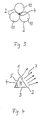
- arrows 7 each show the main direction of propagation of the blown-up extinguishing agent and the pressure wave.
- FIG. 1 shows a flexible hose 2 of any length, which is circular in cross section and made of a thin-walled plastic material, which is filled with an extinguishing agent 10.
- a linear flexible detonating cord 4 made of highly explosive explosive runs within the hose at a distance of about a third of the hose diameter from the bottom of the hose, which is water-resistant, hardly flammable and can be stored almost indefinitely is. With these properties, the explosive can be used both in a mobile and in a stationary application of the extinguishing device.
- the extinguishing agent is atomized into the finest droplet of extinguishing agent by the excess pressure in a fraction of a second and distributed almost uniformly radially in all directions in the direction of the arrows 7. This creates an approximately semicircular cross-section of the extinguishing agent mist on the environment.
- the detonating cord 4 is arranged outside the filled hose 2, an essentially directed detonating and extinguishing effect can be achieved.
- the detonating cord 4 is positioned on the side of the hose 2 facing away from the source of the fire on the floor (not shown). This also helps to fight the fire very effectively, in which far more than 50% of the extinguishing agent can have a direct extinguishing effect.
- detonating cord 4 is arranged in the center of the tube bundle.
- other positions up to the use of several detonating cords at different locations are also conceivable.
- FIG. 4 shows a shape deviating from the circular cross-sectional shape of the tube 2.
- the tube 2 shown there has a triangular cross-sectional shape, and the detonating cord 4 is arranged at the angle of the triangular tube 2, that of the triangular side or tube wall 1 which faces the source of the fire is opposite.
- an essentially directed explosive and extinguishing effect in the direction of arrows 7 can also be achieved.
- This directional effect could be supported, for example, in that the side 1 of the hose 2 facing the source of the fire is made materially weaker than the two other triangle sides 3, 5.
- side 1 can be marked in color in order to ensure proper positioning of the detonating cord in the hose in relation to the source of the fire or the direction of the threat when the extinguishing device is laid out.
- FIG. 5 shows a schematically illustrated forest fire.
- the fire front 8 moves from right to left in the illustration.
- a hose 2 according to FIG. 1 was laid along the entire fire front 8 with the detonating cord 4 contained therein and filled with extinguishing agent. If the detonating cord 4 is detonated, the extinguishing agent atomized into a mist spreads to both sides of the hose 2 over a width of 50 m each.
- the flames 9 are extinguished in the manner described above both by the supercooling effect and by the detonation wave associated with the explosion.
- the area of the forest that was not covered by the fire front 8 is moistened by the extinguishing agent mist.
- FIG. 6 shows a schematically illustrated, irregularly extending fire front 8.
- one advantage of the extinguishing device according to the invention can be shown particularly clearly: if the fire were combated with known, non-flexible extinguishing devices, for example by stringing together rigid extinguishing agent containers along the line 14 shown in broken lines, the extinguishing agent contained in the containers would only have an effect in the most advanced area 17 of the fire front 8 when it was detonated, while in areas 15, 16 no extinguishing effect would be achieved.
- the flexible extinguishing agent hose 2 enables the control line to be adapted to the shape of the flame front 8 and thus a very effective use of the extinguishing agent.
- the extinguishing device can be used in the shortest possible time, since the hose 2 in front of the fire front 8 can be designed like a normal C hose, filled with the extinguishing agent 10 and blasted by igniting the explosive.
- the use of the method according to the invention is also ecologically harmless. The use of extinguishing agent leaves hardly any traces and the loss of biological substance can be reduced to a minimum due to the high efficiency of the process.
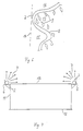
- FIG. 7 shows an example of a stationary application of the extinguishing device in object protection. Shown is a schematic cross section of an oil tank 12, which has a circumferential bracket-like support 6 with an angular cross section at the level of its upper edge 13.
- the hose 2 filled with extinguishing agent rests on the carrier 6.
- the position of the detonating cord 4, which is not shown here, is of secondary importance here.
- the alignment of the explosive and extinguishing effect in the direction of the arrows 7 is achieved in this embodiment by the shielding of the hose on the back by the carrier 6.
- the extinguishing device is automatically detonated by sensors when the fuel contained in the tank 12 ignites.
- the extinguishing agent mist covers the burning fuel like a lid and extinguishes the fire in the manner described above.
- the stationary use of the extinguishing device described in this way can of course also be transferred to the protection of high racks in storage rooms or the like.
- FIG. 8 shows a schematic plan view of an airport runway 18 with an aircraft 19 located thereon.
- the area on a runway 18 in which an emergency landing aircraft 19 comes to a standstill is referred to as a critical area 20, which is indicated here by a dash-dotted line.
- This critical area is approximately 600 to 1,000 meters long and its location can generally be predicted for any type of aircraft.
- Left and right of the runway 18, for example, 5 lengths of tubes 21 are arranged in a total of 10 segments 22 to 31. Depending on where the aircraft 19 comes to a stop during an emergency landing, the corresponding segments 22 to 31 are activated.
- hoses 21 can also be arranged parallel to one another, a second row of hoses (not shown here) could also be used as a so-called “second alarm wave", which is activated when the extinguishing agent supply of the fire-fighting vehicles has been used up.
Landscapes
- Health & Medical Sciences (AREA)
- Emergency Management (AREA)
- Business, Economics & Management (AREA)
- Public Health (AREA)
- Forests & Forestry (AREA)
- Life Sciences & Earth Sciences (AREA)
- Ecology (AREA)
- Biodiversity & Conservation Biology (AREA)
- Fire-Extinguishing By Fire Departments, And Fire-Extinguishing Equipment And Control Thereof (AREA)
- Fire-Extinguishing Compositions (AREA)
- Measurement And Recording Of Electrical Phenomena And Electrical Characteristics Of The Living Body (AREA)
- Respiratory Apparatuses And Protective Means (AREA)
- Chemical And Physical Treatments For Wood And The Like (AREA)
Abstract
Description
Die vorliegende Erfindung betrifft eine Vorrichtung zum Löschen von Bränden, mit einem Behälter zur Aufnahme eines Löschmittels, und mit einem Sprengmittel in oder an diesem Behälter, durch dessen Zündung das Löschmittel zu einem Nebel zerstäubt und in den Brand gebracht wird. Die Erfindung betrifft ferner ein Verfahren zum Löschen von Wald- oder Flächenbränden mit der beschriebenen Vorrichtung.The present invention relates to a device for extinguishing fires, with a container for holding an extinguishing agent, and with an explosive in or on this container, by the ignition of which the extinguishing agent is atomized into a mist and set on fire. The invention further relates to a method for extinguishing forest or wildfires using the described device.
Das Zerstäuben eines Löschmittels in feinste Partikel durch ein Sprengmittel mit dem Ziel, Bränden zu löschen, ist bekannt. Bei der Detonation einer vorzugsweise hochbrisanten Sprengladung innerhalb oder in Nachbarschaft eines homogenen Mediums wie beispielsweise Wasser entsteht ein Druck von mehreren Tausend bar, wodurch das Wasser in feinste Partikel zerstäubt und mit der entstehenden Druckwelle radial vom Zentrum der Sprengladung in die Umgebung geschleudert wird. Unter einer hochbrisanten Sprengladung wird dabei eine solche verstanden, die eine Detonationswelle mit einer Ausbreitungsgeschwindigkeit von über 5000 m/sek erzeugt. Der Löschmittelnebel besitzt im Verhältnis zur eingesetzten Löschmittelmenge aufgrund der geringen Größe der einzelnen Löschmitteltröpfchen eine sehr große Gesamtoberfläche, mit der sich der Löschmittelnebel in der Umgebung des gesprengten Behälters auf das Feuer legt und es durch den bekannten Unterkühlungseffekt löscht. Darüber hinaus beruht die Löschwirkung beim Sprengen eines Löschmittels in bekannter Weise auch auf dem Ausblaseffekt der Detonationswelle.It is known to atomize an extinguishing agent into the finest particles using an explosive with the aim of extinguishing fires. When a preferably explosive explosive charge is detonated inside or in the vicinity of a homogeneous medium such as water, a pressure of several thousand bar arises, as a result of which the water is atomized into extremely fine particles and thrown radially from the center of the explosive charge into the environment with the pressure wave that arises. A high-explosive charge is understood to mean one that generates a detonation wave with a propagation speed of over 5000 m / sec. Due to the small size of the individual droplet droplets, the extinguishing agent mist has a very large total surface in relation to the amount of extinguishing agent used, with which the extinguishing agent mist lies on the fire in the vicinity of the blasted container and extinguishes it by the known supercooling effect. In addition, the extinguishing effect when blasting an extinguishing agent is based in a known manner on the blow-out effect of the detonation wave.
Aus der US 1,119,799 sowie aus der EP 390 384 sind für den stationären Einsatz vorgesehene Feuerlöscher bekannt, die sich den vorstehend beschriebenen Effekt des Sprengens eines Löschmittels zunutze machen. Diese bekannten Vorrichtungenzum Löschen von Bränden weisen einen zylindrischen Behälter zur Aufnahme eines Löschmittels auf, und einen konzentrisch angeordneten länglichen Innenbehälter, der sich in Längsrichtung in dem Löschmittelbehälter erstreckt und mit einer Sprengladung gefüllt ist.From US 1,119,799 and from EP 390 384, fire extinguishers intended for stationary use are known which take advantage of the above-described effect of detonating an extinguishing agent. These known fire extinguishing devices have a cylindrical container for containing an extinguishing agent and a concentrically arranged elongated inner container which extends longitudinally in the extinguishing agent container and is filled with an explosive charge.
Aus der EP 488 536 ist ein solcher Feuerlöscher bekannt, bei dem die Sprengladung im Unterschied zu den beiden vorstehend beschriebenen Feuerlöschern außen am Löschmittelbehälter angebracht ist.Such a fire extinguisher is known from EP 488 536, in which the explosive charge, in contrast to the two fire extinguishers described above, is attached to the outside of the extinguishing agent container.
Die US 3,980,139 und die FR 1,473,621 offenbaren jeweils eine "Feuerlöschbombe", bestehend aus einem zylindrischen Glas bzw. Kunststoffbehälter zur Aufnahme eines Löschmittels, und aus einem zylindrischen, konzentrisch angeordneten Innenbehälter, der wiederum das Sprengmittel beinhaltet. Der Unterschied dieser Feuerlöschbomben zu den vorstehend beschriebenen Feuerlöschern besteht allein in der Zündung des Sprengmittels, die bei den Bomben entweder durch ein Funksignal oder durch Hitzeeinwirkung erfolgt, wenn die Feuerlöschbombe in ein Feuer geworfen wird.US 3,980,139 and FR 1,473,621 each disclose a "fire-fighting bomb" consisting of a cylindrical glass or plastic container for holding an extinguishing agent, and a cylindrical, concentrically arranged inner container which in turn contains the explosive. The difference between these fire-fighting bombs and the fire-extinguishers described above is only the ignition of the explosive, which takes place in the bombs either by a radio signal or by the action of heat when the fire-fighting bomb is thrown into a fire.
Allen vorstehend beschriebenen bekannten Feuerlöschvorrichtungen ist der Nachteil gemeinsam, daß sie in ihrem praktischen Einsatz beim Löschen von Bränden nur ungenügend flexibel und wirksam sind. So haben die stationären Feuerlöscher immer nur eine punktuelle Wirkung, so daß sich ein großflächiger Brandschutz oder auch eine großflächige Bekämpfung eines Brandes aus wirtschaftlichen Gründen verbietet, da zuviele solcher Feuerlöscher eingesetzt werden müßten. Im Hinblick auf die mobile Brandbekämpfung, beispielsweise bei Wald- oder anderen Flächenbränden, haben sich die beschriebenen "Feuerlöschbomben" als nachteilig erwiesen, da sie durch den Abwurf der Löschbombe eine gezielte gerichtete Löschwirkung durch die Sprengung nicht ausüben und darüber hinaus den Brand eher anfachen, wenn sie inmitten des Feuers gezündet werden. Schließlich ist es in großem Maße umständlich und kostenintensiv und nicht zuletzt hinsichtlich der Treffergenauigkeit unbefriedigend, die Löschvorrichtungen über dem Brandherd abzuwerfen.All the known fire extinguishing devices described above have the disadvantage in common that they are only insufficiently flexible and effective in their practical use when extinguishing fires. The stationary fire extinguishers always only have a selective effect, so that large-scale fire protection or large-scale fire fighting is prohibited for economic reasons, since too many such fire extinguishers would have to be used. With regard to mobile fire fighting, for example in forest or other wildfires, the described "fire-fighting bombs" have proven to be disadvantageous, since by dropping the fire-fighting bomb they do not have a targeted, directed extinguishing effect due to the blasting and, moreover, are more likely to ignite the fire if they are ignited in the middle of the fire. After all, it is cumbersome and costly, and not least unsatisfactory in terms of hit accuracy, to drop the extinguishing devices over the source of the fire.
Der vorliegenden Erfindung liegt die Aufgabe zugrunde, eine anpassungsfähigere und effektivere Vorrichtung zum Löschen von Bränden anzugeben.The present invention has for its object to provide a more adaptable and effective device for extinguishing fires.
Diese Aufgabe wird durch die Vorrichtung zum Löschen von Bränden mit den Merkmalen des Anspruchs 1 und mit dem Verfahren zum Löschen von Wald- oder Flächenbränden mit den Merkmalen des Anspruchs 11 gelöst.This object is achieved by the device for extinguishing fires with the features of
Sowohl die erfindungsgemäße Vorrichtung als auch das Verfahren weisen eine ganze Reihe von Vorteilen auf, welche die Effektivität bei der Brandbekämpfung erheblich steigern. Für die nachfolgende Beschreibung der Vorteile soll unter "mobiler" Brandbekämpfung das Löschen von Bränden durch Einsatztrupps verstanden werden. Solche Brände sind beispielsweise Wald- oder Flächenbrände oder auch Brände in industriellen Anlagen oder normalen Gebäuden. Unter "stationärer" Brandbekämpfung soll dabei das Löschen von Bränden mittels einer ständig am Gefahrenort installierten und einsatzbereiten erfindungsgemäßen Löschvorrichtung verstanden werden. Die dadurch zu schützenden Anlagen bzw. Bauten haben ein weites Spektrum; hierunter fallen beispielsweise Öl- oder Gastanks, Raffinerien, Ölbohr- oder -förderanlagen, Landebahnen oder Betankungsplätze auf Flughäfen und ähnliches.Both the device according to the invention and the method have a whole series of advantages which considerably increase the effectiveness in fire fighting. For the following description of the advantages, "mobile" fire fighting means the extinguishing of fires by task forces. Such fires are, for example, forest or wildfires or even fires in industrial plants or normal buildings. "Stationary" fire fighting is to be understood to mean the extinguishing of fires by means of an extinguishing device according to the invention that is permanently installed and ready for use at the hazard location. The systems or buildings to be protected thereby have a wide spectrum; This includes, for example, oil or gas tanks, refineries, oil drilling or production facilities, runways or refueling areas at airports and the like.
Die erfindungsgemäße Löschvorrichtung zeichnet sich beim mobilen Einsatz dadurch aus, daß sie über nahezu unbegrenzte Längen an den Verlauf der Flammenfront und damit an die Bedrohung anpassbar ist. Dabei wird der zunächst nicht mit Löschmittel gefüllte Schlauch wie ein gewöhnlicher Feuerlöschschlauch beispielsweise von Trommeln abgerollt und ausgelegt. Dadurch wird eine nahezu unbegrenzter räumliche Einsatzbreite erzielt. Durch die Anordnung mehrerer parallel zueinander beabstandeter Schlauchlinien lassen sich mehrere Brandbekämpfungslinien und dadurch auch eine nahezu beliebig große Einsatztiefe erzeugen. Der flexible Schlauch ist als Meterware herstellbar und ist in aufgerolltem Zustand leicht transportabel.The extinguishing device according to the invention is distinguished in mobile use in that it can be adapted to the course of the flame front and thus to the threat over almost unlimited lengths. The hose, which is initially not filled with extinguishing agent, is unrolled and laid out, for example from drums, like a conventional fire hose. An almost unlimited spatial range of use is thereby achieved. The arrangement of several hose lines spaced parallel to one another enables several fire-fighting lines and thus an almost unlimited depth of use to be generated. The flexible hose can be manufactured by the meter and is easily transportable when rolled up.
Diese Vorteile machen deutlich, daß die erfindungsgemäße Löschvorrichtung zur Bekämpfung eines Großfeuers in hervorragender Weise geeignet ist. Durch entsprechendes Auslegen des flexiblen Schlauches kann erreicht werden, daß das Feuer "eingehaust" wird, wie der Fachausdruck für das Umzingeln eines Brandherdes unter gleichzeitiger Bekämpfung von allen Seiten lautet.These advantages make it clear that the extinguishing device according to the invention is outstandingly suitable for combating a large fire. By appropriately laying out the flexible hose, it can be achieved that the fire is "enclosed", as the technical term for surrounding a source of fire is, while at the same time fighting from all sides.
Im Hinblick auf die stationäre Brandbekämpfung, d.h. insbesondere für industrielle Anwendungen, zeichnet sich die erfindungsgemäße Löschvorrichtung ebenfalls durch ihre große Flexibilität beim Auslegen aus. Da selbst kleinste Auslegeradien möglich sind, kann die Löschvorrichtung beispielsweise bei der Installation in einer Lagerhalle um Einrichtungsgegenstände wie Regel oder dergleichen oder um bauliche Hindernisse wie Säulen oder dergleichen herumgeführt werden. Auch ein Aufhängen des flexiblen Schlauches über Hochregalen ist denkbar. Somit ist auch hier eine maximale Anpassung der stationären Löschvorrichtung an potentielle Gefahrenherde möglich.With regard to stationary fire fighting, ie especially for industrial applications, the extinguishing device according to the invention is also characterized by its great flexibility in design. Since even the smallest cantilever radii are possible, the extinguishing device can, for example, be guided around furnishings such as rules or the like or around structural obstacles such as columns or the like when installed in a warehouse. It is also conceivable to hang the flexible hose over high racks. Thus, a maximum adaptation of the stationary extinguishing device to potential sources of danger is also possible here.
Für sowohl die mobile als auch die stationäre Brandbekämpfung ist als Vorteil der erfindungsgemäßen Vorrichtung zu nennen, daß der Löschmittelnebel schnell, flexibel und preiswert am Ort des Geschehens erzeugbar ist. Die dafür benötigten Grundstoffe, nämlich Wasser und gegebenenfalls ein Löschmittelzusatz ("RETARDER") sowie das Sprengmittel, sind über lange Zeit problemlos auf engem Raum lagerbar und darüber hinaus gut transportierbar. Daraus ergibt sich auch, daß die erfindungsgemäße Vorrichtung für den stationären Brandschutz dauerhaft installiert oder - für die mobile Brandbekämpfung - variabel vor Ort eingesetzt werden kann, auch dort, wo konventionelle Löschverfahren beispielsweise wegen Wasserknappheit scheitern. Ferner lassen sich durch die erfindungsgemäße Vorrichtung Brände unterschiedlicher Brandklassen sicher ablöschen. Da aufgrund der Oberflächenvergrößerung durch die Zerstäubung des Löschmittels eine verhältnismäßig geringe Menge an Löschmittel eingesetzt wird, werden bei der Brandbekämpfung erheblich geringere Schäden verursacht, als beim Einsatz konventioneller Löschmethoden. Sowohl eine sachgerechte Sprengung selbst als auch das zerstäubte Löschmittel gefährden die Brandumgebung nicht. Beim Einsatz der Löschvorrichtung in solchen Industrien, die pulverartige Produkte herstellen oder verarbeiten, ist es darüber hinaus von großem Vorteil, daß das Pulver nach einer Staubexplosion oder dergleichen durch den Löschmittelnebel großflächig gebunden wird.For both mobile and stationary fire fighting, the advantage of the device according to the invention is that the extinguishing agent mist can be generated quickly, flexibly and inexpensively at the scene. The basic materials required for this, namely water and possibly an extinguishing agent additive ("RETARDER") and the disintegrant, can be stored in a confined space for a long time without any problems and can also be easily transported. It also follows that the device according to the invention for stationary fire protection can be permanently installed or - for mobile fire fighting - can be used variably on site, even where conventional extinguishing methods fail, for example because of water shortages. Furthermore, fires of different fire classes can be extinguished safely by the device according to the invention. Since a relatively small amount of extinguishing agent is used due to the increase in surface area due to the atomization of the extinguishing agent, fire fighting causes far less damage than when conventional extinguishing methods are used. Both proper blasting itself and the atomized extinguishing agent do not endanger the fire environment. When using the extinguishing device in such industries that produce or process powder-like products, it is also of great advantage that the powder is bound by the extinguishing agent mist after a dust explosion or the like.
Vorteilhafte Weiterbildungen der Erfindung sind in den Unteransprüchen angegeben.Advantageous developments of the invention are specified in the subclaims.
Für die Ausbildung des sich in oder an dem Behälter linear erstreckenden Sprengmittels sind zwei Alternativen vorgesehen: Zum einen kann das Sprengmittel als flexible Sprengschnur ausgebildet sein, die sich in Längsrichtung des Schlauches erstreckt, und zum anderen können diskrete lineare Sprengladungen vorgesehen sein, die ebenfalls in Längsrichtung in gleichmäßigen Abständen verteilt in oder an dem Schlauch angeordnet sind. Beiden Ausbildungsformen des Sprengmittels ist als Vorteil gemeinsam, daß der Schlauch mit dem Sprengnittel als fertige Einheit als Meterware herstellbar ist. Das senkt sowohl die Herstellungskosten als auch den Zeitbedarf für den Einsatz vor Ort.Two alternatives are provided for the formation of the explosive that extends linearly in or on the container: firstly, the explosive can be designed as a flexible detonating cord that extends in the longitudinal direction of the hose, and secondly, discrete linear explosive charges can also be provided, which are also shown in FIG Longitudinal direction in uniform Distances are arranged in or on the hose. An advantage of both types of explosives is that the hose with the explosive can be manufactured as a finished unit by the meter. This reduces both the manufacturing costs and the time required for on-site use.
Vorzugsweise besteht der flexible Schlauch aus einem dünnwandigen, aber relativ widerstandsfähigen Material. Die Wahl des Schlauchmaterials wird derart erfolgen, daß es so widerstandsfähig wie nötig und so flexibel wie möglich ist. Hierbei soll die Widerstandsfähigkeit beim mobilen Einsatz lediglich sicherstellen, daß beim Auslegen des Schlauches und beim anschließenden Befüllen mit Löschmittel keine Löcher durch Äste oder spitze Steine verursacht werden. Die Flexibilität wird sich nach den Kriterien ausrichten, daß der Schlauch aufrollbar sein soll und kleinste Auslegeradien möglich sind. Darüber hinaus soll der Schlauch ein möglichst geringes Eigengewicht besitzen. Vorzugsweise kommen dünnwandige Kunststoffschläuche zum Einsatz, die man im Rahmen der vorstehenden Anforderungen als "zerplatzbar" beschreiben könnte. Durch die beschriebene Auswahl des Schlauchmaterials wird ferner eine Gefährdung von Personen durch Wegschleudern harter Materialien, wie sie beispielsweise bei den bekannten Feuerlöschbomben oder dergleichen verwendet werden, vermieden. Bereits Hart-PVC könnte Personen auch auf größere Distanz gefährden.The flexible hose preferably consists of a thin-walled but relatively resistant material. The choice of hose material will be made so that it is as tough as necessary and as flexible as possible. The resistance in mobile use is only intended to ensure that no holes are caused by branches or sharp stones when the hose is laid out and then filled with extinguishing agent. The flexibility will be based on the criteria that the hose should be able to be rolled up and that the smallest extension radii are possible. In addition, the hose should have the lowest possible weight. Thin-walled plastic hoses are preferably used, which could be described as "burstable" within the scope of the above requirements. The selection of the hose material described also avoids endangering people by throwing away hard materials, such as are used, for example, in the known fire-fighting bombs or the like. Even hard PVC could endanger people from a distance.
Darüber hinaus weist der Schlauch einen Schutz gegen Wärmestrahlung auf, indem er beispielsweise aus weißem Material besteht oder eine Aluminiumbeschichtung aufweist.In addition, the hose has protection against heat radiation, for example by being made of white material or having an aluminum coating.
Während der Schlauch üblicherweise einen kreisförmigen Querschnitt haben wird, ist es für besondere Anwendungen auch denkbar, daß der Schlauch im gefüllten Zustand einen dreieckförmigen Querschnitt aufweist. Dieser Querschnitt ermöglicht eine stabile Lage des Schlauchs und damit die Möglichkeit, eine bestimmte Seite des Dreiecks beispielsweise farblich zu kennzeichnen, die dem Brandherd zugewandt sein soll. Das ist insbesondere dann von Vorteil, wenn sich die Sprengschnur in dem Winkel des dreieckförmigen Schlauchs befindet, welcher der dem Brandherd zugewandten Dreieckseite gegenüberliegt. Dadurch läßt sich in besonders effektiver Weise eine gerichtete Sprengwirkung erzielen. Diese kann noch dadurch unterstützt werden, daß die dem Brandherd zugewandte Seite des dreieckförmigen Schlauchs schwächer ausgebildet ist, als die beiden anderen Seiten.While the hose will usually have a circular cross-section, it is also conceivable for special applications that the hose has a triangular cross-section when filled. This cross-section enables a stable position of the hose and thus the possibility to color-code a certain side of the triangle, for example, which should face the source of the fire. This is particularly advantageous if the detonating cord is at the angle of the triangular hose, which is opposite the triangle side facing the source of the fire. A directed explosive effect can thereby be achieved in a particularly effective manner. This can be supported by the fact that the side of the triangular hose facing the source of the fire is weaker than the other two sides.
Ein Ziel beim Sprengen des mit Löschmittel gefüllten Schlauchs ist es, möglichst viel Druck von der Unterfläche, auf der der Schlauch ruht, zu nehmen, um möglichst viel Löschmittel in die Luft zu bringen. Hierzu ist vorzugsweise vorgesehen, daß das Sprengmittel, also beispielsweise ein oder mehrere Sprengschnüre, in einem Abstand von etwa einem Drittel des Schlauchdurchmessers vom Boden oder von einer Halterung, wo der Schlauch aufliegt, entfernt angeordnet ist. Eine solche Positionierung kann am einfachsten dadurch realisiert werden, daß zwei Schläuche parallel aneinandergeklebt werden und die Sprengschnur zwischen den beiden sich berührenden Schläuchen aufgenommen wird. Durch das Anheben der Sprengschnur vom Untergrund ist eine hervorragende Verteilung und Ausrichtung des Löschmittelnebels erzielbar.A goal when blowing up the hose filled with extinguishing agent is to remove as much pressure as possible from the surface on which the hose rests in order to bring as much extinguishing agent into the air. For this purpose, it is preferably provided that the disintegrant, for example one or more detonating cords, is arranged at a distance of approximately one third of the hose diameter from the floor or from a holder where the hose rests. Such a positioning can be realized most simply by gluing two hoses in parallel and picking up the detonating cord between the two hoses in contact. By lifting the detonating cord from the surface, an excellent distribution and alignment of the extinguishing agent mist can be achieved.
Zur Verwendung der Löschvorrichtung zum stationären Objektschutz ist vorgesehen, daß der Schlauch mit dem Sprengmittel auf einem langgestreckten, im Querschnitt beispielsweise schalen- oder winkelförmigen Träger angeordnet ist. Dadurch wird zum einen eine stabile Lagerung des Schlauchs erreicht, und zum anderen eine gerichtete Wirkung bei der Sprengung des Löschmittels, da der Schlauch rückwärtig durch den Träger abgeschirmt ist, während die Wirkung nach vorn in Richtung auf den Gefahrenherd nicht beeinträchtigt wird.To use the extinguishing device for stationary object protection, it is provided that the hose with the disintegrant is arranged on an elongate carrier, for example a bowl-shaped or angular cross-section. On the one hand, this results in a stable storage of the hose, and on the other hand a directed effect when the extinguishing agent is blown up, since the hose is shielded from the rear by the carrier while the forward effect towards the source of the danger is not impaired.
Der Vorteil einer stabilen stationären Lagerung des einsatzbereiten Löschschlauchs ist daran ersichtlich, daß der Schlauch auf dem Träger vorzugsweise ständig mit dem Löschmittel gefüllt sein kann.The advantage of stable, stationary storage of the ready-to-use extinguishing hose can be seen from the fact that the hose on the carrier can preferably be constantly filled with the extinguishing agent.
Die erfindungsgemäße Löschvorrichtung eignet sich neben einer Objekt-Brandschutzvorrichtung für stationäre Anlagen oder Einrichtungen auch zur staubbindung bei Sprengarbeiten, beispielsweise bei Sprengungen von Gebäuden, indem der Schlauch wenigstens teilweise um das zu sprengende Objekt herum ausgelegt, mit Wasser gefüllt und bei Entstehen der Staubfront durch Zünden des Sprengmittels gesprengt wird. Gegebenenfalls können mehrere Schutzwälle um das zu sprengende Objekt herum ausgelegt werden, die dann zeitlich aufeinanderfolgend gezündet werden. Dadurch wird es möglich, die große Staubbelästigung, die bei der Sprengung von Gebäuden bisher anfällt, wirksam zu bekämpfen.In addition to an object fire protection device for stationary systems or facilities, the extinguishing device according to the invention is also suitable for binding dust during blasting work, for example when buildings are blown up, in that the hose is at least partially laid out around the object to be blasted, filled with water and when the dust front arises by ignition of the explosive is blown up. If necessary, several protective walls can be laid out around the object to be blown up, which are then fired sequentially. This makes it possible to effectively combat the great dust nuisance that has previously occurred when buildings are blown up.
Darüber hinaus läßt sich die erfindungsgemäße Löschvorrichtung als präventive Brandschutzvorrichtung an oder auf einer Flughafenlandebahn oder einer Flugzeug-Parkposition verwenden. Aus dem Stand der Technik ist es als Präventivmaßnahme bei einer angesagten Notlandung eines Flugzeugs bekannt, einen ca. 1000 m langen und 60 m breiten Schaumteppich auf die Landebahn aufzubringen. Der Zeitaufwand hierfür beträgt allerdings 45 bis 60 Minuten, und die Kosten für die hierfür erforderliche Ausrüstung sind sehr hoch. Seit einiger Zeit werden Landebahnbeschäumungen nicht mehr durchgeführt, da neben dem enormen Zeit- und Kostenaufwand auch der Sinn einer solchen Beschäumung in Frage gestellt wurde. Durch den Schaumteppich kann das Flugzeug bei der Notlandung nämlich unkontrollierbar werden und seitlich von der Landebahn ausscheren, so daß die Rettungsarbeiten dadurch eher behindert werden. Dabei ist der kritische Moment und damit auch die kritische Position bei der Notlandung eines Flugzeugs erst dann erreicht, wenn dieses zum Stillstand kommt und auslaufender Treibstoff entzündet wird. Genau an diesem Punkt setzt die erfindungsgemäße Löschvorrichtung an, indem der Schlauch entlang der Landebahn ausgelegt, mit dem Löschmittel gefüllt und im kritischen Moment durch Zünden des Sprengmittels gesprengt wird. Die durch das Sprengen erzeugten feinsten Löschmittelpartikel regnen auf den aktivierten kritischen Bereich herab und bilden einen Oberflächenfilm, der innerhalb kürzester Zeit zu einer geschlossenen Oberfläche führt und damit ein Entzünden des Treibstoffs verhindert.In addition, the extinguishing device according to the invention can be used as a preventive fire protection device on or on an airport runway or an aircraft parking position. As a preventive measure in the event of a hip emergency landing of an aircraft, it is known from the prior art to apply an approximately 1000 m long and 60 m wide foam carpet to the runway. However, this takes 45 to 60 minutes, and the cost of the equipment required for this is very high. Runway foaming has not been carried out for some time because, in addition to the enormous expenditure of time and money, the meaning of such foaming has been questioned. Because of the foam carpet, the aircraft can become uncontrollable during the emergency landing and move out of the side of the runway, so that the rescue work are more likely to be hindered. The critical moment and thus also the critical position in the emergency landing of an aircraft is only reached when the aircraft comes to a standstill and fuel that leaks is ignited. This is exactly where the extinguishing device according to the invention comes into play by laying the hose along the runway, filling it with the extinguishing agent and detonating it at the critical moment by igniting the explosive. The finest extinguishing agent particles generated by the blasting rain down on the activated critical area and form a surface film that leads to a closed surface within a very short time and thus prevents the fuel from igniting.
Eine weitere Einsatzmöglichkeit der erfindungsgemäßen Löschvorrichtung besteht im präventiven Brandschutz einer Flugzeug-Parkposition, wo die Flugzeuge in aller Regel auch betankt werden. Dort wäre es denkbar, zwischen dem Flugzeug und dem Terminalgebäude eine Schlauchfront zu installieren, die ständig mit Löschmittel gefüllt sein kann und im Notfall durch Sprengung einen feinsten Löschmittelfilm über den geschützten Bereich legt.Another possible application of the extinguishing device according to the invention is in preventive fire protection in an aircraft parking position, where the aircraft are generally also refueled. There it would be conceivable to install a hose front between the aircraft and the terminal building, which can be constantly filled with extinguishing agent and, in an emergency, can lay a finest film of extinguishing agent over the protected area.
Im folgenden wird die Erfindung in einigen Ausführungsbeispielen anhand einer Zeichnung näher erläutert.In the following, the invention is explained in more detail in some exemplary embodiments with reference to a drawing.
Es zeigen:
Figur 1- einen schematischen Querschnitt eines Spreng-Löschschlauches mit innenliegendem Sprengmittel;
Figur 2- einen schematischen Querschnitt eines Spreng-Löschschlauches mit außenliegendem Sprengmittel;
Figur 3- einen schematischen Querschnitt eines Schlauchbündels aus drei Spreng-Löschschläuchen;
Figur 4- einen schematischen Querschnitt eines dreieckförmigen Spreng-Löschschlauches;
Figur 5- eine schematische Ansicht eines Waldbrandes mit linienförmigem Verlauf der Flammenfront;
- Figur 6
- eine schematische Ansicht eines Waldbrandes mit unregelmäßigem Verlauf der Flammenfront;
- Figur 7
- eine schematische Darstellung eines Öltanks mit stationär angeordneter Löschvorrichtung im Querschnitt; und
- Fig. 8
- eine schematische Darstellung einer Landebahn eines Flughafens mit stationär angeordneter Löschvorrichtung in der Draufsicht.
- Figure 1
- a schematic cross section of an explosive fire hose with internal explosive;
- Figure 2
- a schematic cross section of an explosive fire hose with external explosive;
- Figure 3
- a schematic cross section of a hose bundle from three explosive fire hoses;
- Figure 4
- a schematic cross section of a triangular explosive fire hose;
- Figure 5
- a schematic view of a forest fire with a linear course of the flame front;
- Figure 6
- a schematic view of a forest fire with an irregular course of the flame front;
- Figure 7
- a schematic representation of an oil tank with a stationary extinguishing device in cross section; and
- Fig. 8
- a schematic representation of an airport runway with stationary extinguishing device in plan view.
In den Figuren der Zeichnung zeigen die Pfeile 7 jeweils die Haupt-Ausbreitungsrichtung des gesprengten Löschmittels und der Druckwelle.In the figures of the drawing, arrows 7 each show the main direction of propagation of the blown-up extinguishing agent and the pressure wave.
Figur 1 zeigt einen im Querschnitt kreisförmigen flexiblen Schlauch 2 beliebiger Länge aus einem dünnwandigen Kunststoffmaterial, der mit einem Löschmittel 10 gefüllt ist. Dort, wo der Schlauch 2 auf dem (nicht dargestellten) Boden aufliegt, verläuft innerhalb des Schlauches in einem Abstand von etwa einem Drittel des Schlauchdurchmessers vom Boden des Schlauchs eine lineare flexible Sprengschnur 4 aus hochbrisantem Sprengstoff, der wasserbeständig, kaum brennbar und fast unbegrenzt lagerfähig ist. Mit diesen Eigenschaften kann das Sprengmittel sowohl bei einer mobilen als auch bei einer stationären Anwendung der Löschvorrichtung Verwendung finden.FIG. 1 shows a
Wird die Sprengschnur 4 gezündet, wird das Löschmittel durch den Überdruck in Bruchteilen einer Sekunde in feinste Löschmitteltröpfchen zerstäubt und in Richtung der Pfeile 7 nahezu gleichmäßig in alle Richtungen radial verteilt. Somit entsteht eine im Querschnitt etwa halbkreisförmige Abgabe des Löschmitelnebels auf die Umgebung.If the detonating
Wird stattdessen, wie in Figur 2 dargestellt, die Sprengschnur 4 außerhalb des gefüllten Schlauches 2 angeordnet, so läßt sich eine im wesentlichen gerichtete Spreng- und Löschwirkung erzielen. Hierbei ist die Sprengschnur 4 auf der dem Brandherd abgewandten Seite des Schlauches 2 am (nicht dargestellten) Boden positioniert. Dadurch wird eine ebenfalls sehr wirksame Bekämpfung des Brandes erreicht, bei der weit mehr als 50 % des Löschmittels eine direkte Löschwirkung entfalten können.If instead, as shown in FIG. 2, the detonating
In manchen Fällen kann es sinnvoll sein, aus mehreren Schläuchen 2 ein Schlauchbündel zu bilden, wie es in Figur 3 schematisch im Querschnitt dargestellt ist. Hier ist die Sprengschnur 4 im Zentrum des Schlauchbündels angeordnet. Selbstverständlich sind aber auch andere Positionierungen bis hin zur Verwendung mehrerer Sprengschnüre an verschiedenen Stellen denkbar.In some cases it can be useful to form a tube bundle from
Eine von der kreisförmigen Querschnittsform des Schlauchs 2 abweichende Form zeigt Figur 4. Der dort dargestellte Schlauch 2 besitzt eine dreieckförmige Querschnittsform, und die Sprengschnur 4 ist in dem Winkel des dreieckförmigen Schlauchs 2 angeordnet, der der Dreiecksseite bzw. Schlauchwandung 1, die dem Brandherd zugewandt ist, gegenüberliegt. Durch diese Anordnung ist ebenfalls eine im wesentlichen gerichtete Spreng- und Löschwirkung in Richtung der Pfeile 7 erzielbar. Diese Richtungswirkung könnte beispielsweise dadurch unterstützt werden, daß die dem Brandherd zugewandte Seite 1 des Schlauches 2 materiell schwächer ausgebildet ist, als die beiden anderen Dreiecksseiten 3, 5. Darüber hinaus kann die Seite 1 farbig markiert sein, um beim Auslegen der Löschvorrichtung eine ordnungsgemäße Positionierung der im Schlauch befindlichen Sprengschnur in Bezug auf den Brandherd oder die Bedrohungsrichtung sicherzustellen.FIG. 4 shows a shape deviating from the circular cross-sectional shape of the
Figur 5 zeigt einen schematisch dargestellten Waldbrand. Die Feuerfront 8 bewegt sich in der Darstellung von rechts nach links. Zum Löschen des Brandes wurde entlang der gesamten Feuerfront 8 beispielsweise ein Schlauch 2 gemäß Figur 1 mit der darin enthaltenen Sprengschnur 4 ausgelegt und mit Löschmittel gefüllt. Wird die Sprengschnur 4 gezündet, breitet sich das zu einem Nebel zerstäubte Löschmittel zu beiden Seiten des Schlauchs 2 auf einer Breite von je 50 m aus. Die Flammen 9 werden in der vorstehend beschriebenen Weise sowohl durch den Unterkühlungseffekt als auch durch die mit der Sprengung einhergehende Detonationswelle gelöscht. Auf der gegenüberliegenden Seite des Schlauchs 2 wird der Bereich des Waldes, der nicht von der Feuerfront 8 erfaßt wurde, durch den Löschmittelnebel befeuchtet.Figure 5 shows a schematically illustrated forest fire. The
Figur 6 zeigt eine schematisch dargestellte unregelmäßig verlaufende Feuerfront 8. Anhand dieser schematischen Darstellung läßt sich ein Vorteil der erfindungsgemäßen Löschvorrichtung besonders deutlich zeigen: Würde das Feuer mit bekannten, nicht flexiblen Löschvorrichtungen bekämpft, beispielsweise durch eine Aneinanderreihung starrer Löschmittelbehälter entlang der gestrichelt dargestellten Linie 14, so würde sich das in den Behältern enthaltene Löschmittel bei dessen Sprengung lediglich in dem am weitesten fortgeschrittenen Bereich 17 der Feuerfront 8 auswirken, während in den Bereichen 15, 16 keine Löschwirkung erzielt würde. Demgegenüber ermöglicht der flexible Löschmittelschlauch 2 eine Anpassung der Bekämpfungslinie an den Verlauf der Flammenfront 8 und damit einen sehr effektiven Einsatz des Löschmittels. Darüber hinaus ist die Löschvorrichtung in kürzester Zeit einsetzbar, da der Schlauch 2 vor der Feuerfront 8 wie ein gewöhnlicher C-Schlauch ausgelegt, mit dem Löschmittel 10 gefüllt und durch Zünden des Sprengmittels gesprengt werden kann. Hierbei ist durch die Oberflächenvergrößerung des Löschmittels aufgrund der Zerstäubung zu einem feinen Nebel ein optimaler Wirkungsgrad der eingesetzten Löschmittelmenge erzielbar. Ferner ist die Anwendung des erfindungsgemäßen Verfahrens auch ökologisch unbedenklich. Der Löschmitteleinsatz hinterläßt kaum Spuren und der Verlust biologischer Substanz ist durch die hohe Effizienz des Verfahrens auf ein Minimum reduzierbar.FIG. 6 shows a schematically illustrated, irregularly extending
Figur 7 zeigt ein Beispiel für eine stationäre Anwendung der Löschvorrichtung im Objektschutz. Dargestellt ist ein schematischer Querschnitt eines Öltanks 12, der in Höhe seines oberen Randes 13 einen umlaufenden konsolenartigen Träger 6 mit winkelförmigem Querschnitt aufweist. Auf dem Träger 6 ruht der mit Löschmittel gefüllte Schlauch 2. Die Position der Sprengschnur 4, die hier nicht dargestellt ist, ist hier von untergeordneter Bedeutung. Die Ausrichtung der Spreng- und Löschwirkung in Richtung der Pfeile 7 wird in diesem Ausführungsbeispiel durch die Abschirmung des Schlauches auf der Rückseite durch den Träger 6 erzielt. Die Löschvorrichtung wird durch Sensoren automatisch zur Detonation gebracht, wenn sich der im Tank 12 enthaltene Brennstoff entzündet. Unmittelbar nach der Detonation legt sich der Löschmittelnebel wie ein Deckel über den brennenden Brennstoff und löscht den Brand auf die vorstehend beschriebene Art und Weise. Der so beschriebene stationäre Einsatz der Löschvorrichtung ist selbstverständlich auch auf den Schutz von Hochregalen in Lagerräumen oder dergleichen übertragbar.FIG. 7 shows an example of a stationary application of the extinguishing device in object protection. Shown is a schematic cross section of an
Figur 8 zeigt eine schematische Draufsicht auf eine Landebahn 18 eines Flughafens mit einem darauf befindlichen Flugzeug 19.FIG. 8 shows a schematic plan view of an
Den Bereich auf einer Landebahn 18, in dem ein notgelandetes Flugzeug 19 zum Stillstand kommt, wird als kritischer Bereich 20 bezeichnet, der hier mit einer strichpunktierten Linie angedeutet ist. Dieser kritische Bereich ist etwa 600 bis 1.000 m lang, und seine Lage kann im allgemeinen für jeden Flugzeugtyp vorausgesagt werden. Links und rechts der Landebahn 18 sind beispielhaft jeweils 5 Längen von Schläuchen 21 in insgesamt 10 Segmenten 22 bis 31 angeordnet. Je nachdem, wo das Flugzeug 19 bei einer Notlandung zum Stillstand kommt, werden die entsprechenden Segmente 22 bis 31 aktiviert. Da auch mehrere solcher Schläuche 21 parallel nebeneinander angeordnet werden können, könnte eine (hier nicht dargestellte) zweite Schlauchreihe auch als sogenannte "zweite Alarmwelle" benutzt werden, die dann aktiviert wird, wenn der Löschmittelvorrat der Löschfahrzeuge verbraucht ist.The area on a
Claims (11)
- Device for extinguishing fires, with a container for receiving an extinguishing agent (10), and with an explosive in or on said container, by means of the detonation of which the extinguishing agent (10) is atomised to form a mist and is applied to the fire,
characterised in that
the container is a flexible hose (2) closable at both ends. - Device according to claim 1,
characterised in that
the explosive is in the form of a flexible explosive cord (4) which extends in the longitudinal direction of the hose (2). - Device according to claim 1,
characterised in that
the explosive is in the form of discrete linear explosive charges, and is distributed at regular intervals. - Device according to one of claims 1 to 3,
characterised in that
the hose (2) comprises a thin-walled but resistant material. - Device according to one of claims 1 to 4,
characterised in that
the hose (2) comprises a material reflective of radiant heat, or has a protective coating for this purpose. - Device according to one of claims 1 to 5,
characterised in that
the explosive is located at a distance of approximately one-third of the hose diameter away from the ground or from a retaining means upon which the hose (2) rests. - Device according to one of claims 1 to 6,
characterised in that
the hose (2) is disposed with the explosive on a longitudinally-extended carrier (6) which is for example shell-shaped or angled in cross-section. - Use of the device according to one or more of claims 1 to 7 as a fire-protection device for specific objects, for stationary installations or devices.
- Use of the device according to one or more of claims 1 to 7 for dust-abatement during blasting operations,
characterised in that
the hose is laid at least partly around the object to be blasted, is filled with water and is detonated by ignition of the explosive when the dust front arises. - Use of the device according to one or more of claims 1 to 7 as a preventative fire-protection device at or on an aircraft runway, or an aircraft parking area,
characterised in that
the hose (2) is laid out at least partly along the runway or around the parking area to be protected, is filled with the extinguishing agent (10), and is detonated by ignition of the explosive when a fire risk occurs. - Method of extinguishing forest or terrain fires with a device according to one or more of claims 1 to 7,
characterised in that
the hose (2) is laid out in front of the flame front (8), is filled with the extinguishing agent (10) and is detonated by ignition of the explosive.
Applications Claiming Priority (5)
| Application Number | Priority Date | Filing Date | Title |
|---|---|---|---|
| DE4427889 | 1994-08-08 | ||
| DE4427889 | 1994-08-08 | ||
| DE19500477A DE19500477C1 (en) | 1994-08-08 | 1995-01-10 | Fire extinguisher with container esp. for forest fires |
| DE19500477 | 1995-01-10 | ||
| PCT/EP1995/002964 WO1996004960A1 (en) | 1994-08-08 | 1995-07-26 | Method and device for extinguishing fires |
Publications (2)
| Publication Number | Publication Date |
|---|---|
| EP0760719A1 EP0760719A1 (en) | 1997-03-12 |
| EP0760719B1 true EP0760719B1 (en) | 1997-08-20 |
Family
ID=25939001
Family Applications (1)
| Application Number | Title | Priority Date | Filing Date |
|---|---|---|---|
| EP95927731A Expired - Lifetime EP0760719B1 (en) | 1994-08-08 | 1995-07-26 | Method and device for extinguishing fires |
Country Status (22)
| Country | Link |
|---|---|
| US (1) | US5894891A (en) |
| EP (1) | EP0760719B1 (en) |
| JP (1) | JP3078016B2 (en) |
| KR (1) | KR100419035B1 (en) |
| AT (1) | ATE157031T1 (en) |
| AU (1) | AU684663B2 (en) |
| BR (1) | BR9508986A (en) |
| CA (1) | CA2177969C (en) |
| DE (2) | DE19500477C1 (en) |
| DK (1) | DK0760719T3 (en) |
| ES (1) | ES2108584T3 (en) |
| GR (1) | GR3025329T3 (en) |
| HR (1) | HRP950434B1 (en) |
| IL (1) | IL114788A (en) |
| MA (1) | MA23642A1 (en) |
| NO (1) | NO307034B1 (en) |
| NZ (1) | NZ290821A (en) |
| SG (1) | SG63523A1 (en) |
| TR (1) | TR199500980A2 (en) |
| TW (1) | TW303301B (en) |
| WO (1) | WO1996004960A1 (en) |
| YU (1) | YU48696B (en) |
Families Citing this family (30)
| Publication number | Priority date | Publication date | Assignee | Title |
|---|---|---|---|---|
| DE19539210A1 (en) * | 1995-10-21 | 1997-04-24 | Dynamit Nobel Ag | Extinguishing chain for fighting fires |
| DE19643929C2 (en) * | 1996-10-30 | 1998-08-06 | Wagner Alarm Sicherung | Device and method for extinguishing fires |
| DE19915840A1 (en) * | 1999-04-08 | 2000-10-12 | Anton Neumeir | Method and device for extinguishing forest fires from the air |
| DE10014543A1 (en) * | 2000-03-23 | 2001-09-27 | Klaus Spies | Pressure generator for fire extinguishing or sprinkler system, uses explosives to produce combustion gas to exert pressure on medium |
| US6318473B1 (en) | 2000-08-18 | 2001-11-20 | Talmadge O. Bartley | Expansive fire extinguishing system |
| US6796382B2 (en) | 2001-07-02 | 2004-09-28 | Siam Safety Premier Co., Ltd. | Fire extinguishing ball |
| US7090028B2 (en) * | 2001-09-19 | 2006-08-15 | Nanomist Systems, Llc | Fire suppression using water mist with ultrafine size droplets |
| DE10206815B4 (en) * | 2002-02-19 | 2004-02-12 | Pinnig, Jörg | Device and method for extinguishing fires |
| CN100544796C (en) * | 2002-08-09 | 2009-09-30 | 法纳瓦南·凯玛特 | Fire extinguishing ball |
| DE10346163A1 (en) | 2003-10-04 | 2005-05-04 | Diehl Bgt Defence Gmbh & Co Kg | Missile for fire fighting |
| CA2554499C (en) * | 2004-02-06 | 2014-01-14 | Jeffrey P. Reistroffer | Linear incendiary strand and method for prescribed fire ignition |
| KR200372978Y1 (en) * | 2004-07-21 | 2005-01-14 | 심화준 | Powder-type unmanned automatic fire extinguishing and emergency injection device |
| FR2876920B1 (en) * | 2004-10-26 | 2007-07-06 | Claude Piveau | PIPE FOR STOPPING A FIRE |
| US20080087444A1 (en) * | 2006-10-12 | 2008-04-17 | Held Jerry M | New technique for fire fighting-large scale open fires |
| US20080289831A1 (en) * | 2007-05-25 | 2008-11-27 | Kaimart Phanawatnan Woradech | Fire extinguishing device |
| CZ307311B6 (en) * | 2010-01-13 | 2018-05-30 | Univerzita Tomáše Bati ve Zlíně | A method of extinguishing local surface fires by means of blasting techniques |
| RU2458716C1 (en) * | 2011-03-21 | 2012-08-20 | Государственное образовательное учреждение высшего профессионального образования Томский государственный университет (ТГУ) | Combined method of isolation and extinguishing creeping forest and grassland fires |
| US8807004B1 (en) | 2011-08-04 | 2014-08-19 | James Y. Menefee, III | Recoil attenuated payload launcher system |
| US10054410B2 (en) | 2011-08-04 | 2018-08-21 | James Y. Menefee, III | Cartridge for handheld payload launcher system |
| US9383161B2 (en) | 2011-08-04 | 2016-07-05 | James Y. Menefee, III | Handheld payload launcher system |
| RU2496539C1 (en) * | 2012-05-05 | 2013-10-27 | Федеральное государственное бюджетное образовательное учреждение высшего профессионального образования "Национальный исследовательский Томский государственный университет" (ТГУ) | Plated cord charge for localisation of ground forest and steppe fires |
| CN103432700B (en) * | 2013-09-16 | 2015-03-18 | 国家电网公司 | Method for quickly extinguishing mountain fire along power transmission lines |
| US9808660B2 (en) | 2015-03-31 | 2017-11-07 | Robert Shane Kilburn | Fire fighting apparatus and method |
| US10318904B2 (en) | 2016-05-06 | 2019-06-11 | General Electric Company | Computing system to control the use of physical state attainment of assets to meet temporal performance criteria |
| US10653904B2 (en) | 2017-12-02 | 2020-05-19 | M-Fire Holdings, Llc | Methods of suppressing wild fires raging across regions of land in the direction of prevailing winds by forming anti-fire (AF) chemical fire-breaking systems using environmentally clean anti-fire (AF) liquid spray applied using GPS-tracking techniques |
| US11865390B2 (en) | 2017-12-03 | 2024-01-09 | Mighty Fire Breaker Llc | Environmentally-clean water-based fire inhibiting biochemical compositions, and methods of and apparatus for applying the same to protect property against wildfire |
| US11865394B2 (en) | 2017-12-03 | 2024-01-09 | Mighty Fire Breaker Llc | Environmentally-clean biodegradable water-based concentrates for producing fire inhibiting and fire extinguishing liquids for fighting class A and class B fires |
| US11826592B2 (en) | 2018-01-09 | 2023-11-28 | Mighty Fire Breaker Llc | Process of forming strategic chemical-type wildfire breaks on ground surfaces to proactively prevent fire ignition and flame spread, and reduce the production of smoke in the presence of a wild fire |
| US11911643B2 (en) | 2021-02-04 | 2024-02-27 | Mighty Fire Breaker Llc | Environmentally-clean fire inhibiting and extinguishing compositions and products for sorbing flammable liquids while inhibiting ignition and extinguishing fire |
| DE102021004284A1 (en) | 2021-08-21 | 2023-02-23 | Kastriot Merlaku | Fire brigade extinguishing nozzle or fire brigade multi-purpose nozzle |
Family Cites Families (10)
| Publication number | Priority date | Publication date | Assignee | Title |
|---|---|---|---|---|
| US1080068A (en) * | 1913-01-03 | 1913-12-02 | Alphonse La Breche | Automatic fire-extinguisher. |
| US1119799A (en) * | 1913-09-15 | 1914-12-08 | Charles M Bowman | Fire-extinguisher. |
| FR1473621A (en) * | 1966-03-30 | 1967-03-17 | Fire extinguisher | |
| LU66154A1 (en) * | 1972-09-25 | 1974-04-02 | ||
| US3980139A (en) * | 1975-09-15 | 1976-09-14 | Norman Kirk | Fire extinguishing bomb for putting out fires |
| US4938293A (en) * | 1987-04-29 | 1990-07-03 | Systron Donner Corp. | Linear fire extinguisher |
| FR2620033A1 (en) * | 1987-09-07 | 1989-03-10 | Collard Catherine | Device for rapidly creating a continuous wet zone which can combat and extinguish forest fires in strong winds and during the night |
| EP0390384A1 (en) * | 1989-03-31 | 1990-10-03 | Kidde-Graviner Limited | Fire extinguishers |
| US5050683A (en) * | 1990-05-14 | 1991-09-24 | The United States Of America As Represented By The Secretary Of The Army | Extinguishing rocket/missile solid propellants |
| US5088560A (en) * | 1990-11-01 | 1992-02-18 | Systron Donner Corporation | Zero force fire extinguisher |
-
1995
- 1995-01-10 DE DE19500477A patent/DE19500477C1/en not_active Expired - Fee Related
- 1995-07-26 US US08/649,640 patent/US5894891A/en not_active Expired - Lifetime
- 1995-07-26 EP EP95927731A patent/EP0760719B1/en not_active Expired - Lifetime
- 1995-07-26 DK DK95927731.0T patent/DK0760719T3/en active
- 1995-07-26 WO PCT/EP1995/002964 patent/WO1996004960A1/en active IP Right Grant
- 1995-07-26 KR KR1019970700849A patent/KR100419035B1/en not_active IP Right Cessation
- 1995-07-26 ES ES95927731T patent/ES2108584T3/en not_active Expired - Lifetime
- 1995-07-26 JP JP08506951A patent/JP3078016B2/en not_active Expired - Fee Related
- 1995-07-26 CA CA002177969A patent/CA2177969C/en not_active Expired - Fee Related
- 1995-07-26 BR BR9508986A patent/BR9508986A/en not_active IP Right Cessation
- 1995-07-26 DE DE59500541T patent/DE59500541D1/en not_active Expired - Lifetime
- 1995-07-26 AT AT95927731T patent/ATE157031T1/en active
- 1995-07-26 NZ NZ290821A patent/NZ290821A/en unknown
- 1995-07-26 AU AU31664/95A patent/AU684663B2/en not_active Ceased
- 1995-07-31 IL IL11478895A patent/IL114788A/en not_active IP Right Cessation
- 1995-08-02 SG SG1995001030A patent/SG63523A1/en unknown
- 1995-08-02 HR HR950434A patent/HRP950434B1/en not_active IP Right Cessation
- 1995-08-05 TW TW084108174A patent/TW303301B/zh not_active IP Right Cessation
- 1995-08-07 YU YU53495A patent/YU48696B/en unknown
- 1995-08-08 TR TR95/00980A patent/TR199500980A2/en unknown
- 1995-08-08 MA MA23983A patent/MA23642A1/en unknown
-
1996
- 1996-07-17 NO NO962992A patent/NO307034B1/en unknown
-
1997
- 1997-11-11 GR GR970402971T patent/GR3025329T3/en unknown
Also Published As
| Publication number | Publication date |
|---|---|
| AU3166495A (en) | 1996-03-07 |
| MA23642A1 (en) | 1996-04-01 |
| SG63523A1 (en) | 1999-03-30 |
| GR3025329T3 (en) | 1998-02-27 |
| KR100419035B1 (en) | 2004-07-27 |
| JP3078016B2 (en) | 2000-08-21 |
| WO1996004960A1 (en) | 1996-02-22 |
| IL114788A (en) | 1999-07-14 |
| DK0760719T3 (en) | 1998-04-06 |
| MX9700972A (en) | 1998-07-31 |
| DE59500541D1 (en) | 1997-09-25 |
| AU684663B2 (en) | 1997-12-18 |
| CA2177969A1 (en) | 1996-02-22 |
| US5894891A (en) | 1999-04-20 |
| CA2177969C (en) | 1999-12-28 |
| HRP950434B1 (en) | 2000-08-31 |
| IL114788A0 (en) | 1995-11-27 |
| HRP950434A2 (en) | 1997-06-30 |
| TW303301B (en) | 1997-04-21 |
| ATE157031T1 (en) | 1997-09-15 |
| JPH10508214A (en) | 1998-08-18 |
| NO307034B1 (en) | 2000-01-31 |
| NO962992L (en) | 1996-07-17 |
| TR199500980A2 (en) | 1996-06-21 |
| NZ290821A (en) | 1997-05-26 |
| EP0760719A1 (en) | 1997-03-12 |
| NO962992D0 (en) | 1996-07-17 |
| DE19500477C1 (en) | 1995-11-23 |
| ES2108584T3 (en) | 1997-12-16 |
| BR9508986A (en) | 1997-11-11 |
| YU53495A (en) | 1997-12-05 |
| YU48696B (en) | 1999-07-28 |
Similar Documents
| Publication | Publication Date | Title |
|---|---|---|
| EP0760719B1 (en) | Method and device for extinguishing fires | |
| US7261165B1 (en) | Appartus for fighting forest fires | |
| US7210537B1 (en) | Method of controlling fires | |
| EP1520604A2 (en) | Fire fighting missile | |
| WO1997006858A2 (en) | Process and device for fighting fires from the air | |
| EP1716890A1 (en) | Method and device for controlling and/or putting out fires | |
| DE69014111T2 (en) | ARRANGEMENT OF A SMOKE-DEVELOPING CAMOUFLAGE SYSTEM. | |
| EP2283902A1 (en) | Extinguishing apparatus and method for local fire-fighting | |
| DE3876335T2 (en) | FIRE-FIGHTING METHOD AND USE OF THIS METHOD. | |
| DE4427326B4 (en) | Stationary fire extinguishing system | |
| DE977984C (en) | ||
| WO1998039064A1 (en) | Explosive fire extinguishing device | |
| EP1007159B1 (en) | Pyrotechnical device and process for extinguishing fires | |
| EP0010734B1 (en) | Equipment proofed against explosion and detonation | |
| DE102006058446A1 (en) | Fire extinguisher for extinguishing fire i.e. peat fire, in aircraft, has strong container with blasting charge and extinguishing agent, and with points of fracture, and tube with round or polygonal cross-section for accommodation of charge | |
| DE2459633A1 (en) | Movable protection arrangement for armoured vehicles - is pivoted on vehicle and supports antitank projectile catcher | |
| EP0696463A2 (en) | Method and device for transfering payloads to a remote area | |
| DE3022460A1 (en) | Method for laying smoke screen using carrier projectiles - with first screen laid in close proximity to protected position, and further screens at increasing distances and heights | |
| DE102007061108B4 (en) | Method and apparatus for firefighting | |
| RU2083245C1 (en) | Fire-proof protective barrier | |
| EP0848967B1 (en) | Apparatus for extinguishing fires | |
| DE202022002151U1 (en) | Device for cooling and/or fire fighting | |
| DE1960529A1 (en) | Fire extinguishing system | |
| DE738880C (en) | Gas container ceiling protected against fire bombs | |
| MXPA97000972A (en) | Procedure and device for deincend extinction |
Legal Events
| Date | Code | Title | Description |
|---|---|---|---|
| PUAI | Public reference made under article 153(3) epc to a published international application that has entered the european phase |
Free format text: ORIGINAL CODE: 0009012 |
|
| GRAG | Despatch of communication of intention to grant |
Free format text: ORIGINAL CODE: EPIDOS AGRA |
|
| 17P | Request for examination filed |
Effective date: 19960524 |
|
| AK | Designated contracting states |
Kind code of ref document: A1 Designated state(s): AT BE CH DE DK ES FR GB GR IE IT LI NL PT SE |
|
| 17Q | First examination report despatched |
Effective date: 19970313 |
|
| GRAH | Despatch of communication of intention to grant a patent |
Free format text: ORIGINAL CODE: EPIDOS IGRA |
|
| GRAH | Despatch of communication of intention to grant a patent |
Free format text: ORIGINAL CODE: EPIDOS IGRA |
|
| GRAA | (expected) grant |
Free format text: ORIGINAL CODE: 0009210 |
|
| AK | Designated contracting states |
Kind code of ref document: B1 Designated state(s): AT BE CH DE DK ES FR GB GR IE IT LI NL PT SE |
|
| REF | Corresponds to: |
Ref document number: 157031 Country of ref document: AT Date of ref document: 19970915 Kind code of ref document: T |
|
| REG | Reference to a national code |
Ref country code: CH Ref legal event code: EP |
|
| GBT | Gb: translation of ep patent filed (gb section 77(6)(a)/1977) |
Effective date: 19970820 |
|
| REF | Corresponds to: |
Ref document number: 59500541 Country of ref document: DE Date of ref document: 19970925 |
|
| ET | Fr: translation filed | ||
| REG | Reference to a national code |
Ref country code: CH Ref legal event code: NV Representative=s name: ANDRE BRAUN PATENTANWALT VSP |
|
| ITF | It: translation for a ep patent filed | ||
| REG | Reference to a national code |
Ref country code: ES Ref legal event code: FG2A Ref document number: 2108584 Country of ref document: ES Kind code of ref document: T3 |
|
| REG | Reference to a national code |
Ref country code: GR Ref legal event code: FG4A Free format text: 3025329 |
|
| REG | Reference to a national code |
Ref country code: PT Ref legal event code: SC4A Free format text: AVAILABILITY OF NATIONAL TRANSLATION Effective date: 19971119 |
|
| REG | Reference to a national code |
Ref country code: DK Ref legal event code: T3 |
|
| PLBE | No opposition filed within time limit |
Free format text: ORIGINAL CODE: 0009261 |
|
| STAA | Information on the status of an ep patent application or granted ep patent |
Free format text: STATUS: NO OPPOSITION FILED WITHIN TIME LIMIT |
|
| 26N | No opposition filed | ||
| REG | Reference to a national code |
Ref country code: GB Ref legal event code: IF02 |
|
| PGFP | Annual fee paid to national office [announced via postgrant information from national office to epo] |
Ref country code: DK Payment date: 20070713 Year of fee payment: 13 |
|
| PGFP | Annual fee paid to national office [announced via postgrant information from national office to epo] |
Ref country code: IE Payment date: 20070720 Year of fee payment: 13 |
|
| REG | Reference to a national code |
Ref country code: CH Ref legal event code: NV Representative=s name: BRAUNPAT BRAUN EDER AG |
|
| PGFP | Annual fee paid to national office [announced via postgrant information from national office to epo] |
Ref country code: SE Payment date: 20070712 Year of fee payment: 13 Ref country code: NL Payment date: 20070716 Year of fee payment: 13 Ref country code: BE Payment date: 20070802 Year of fee payment: 13 |
|
| REG | Reference to a national code |
Ref country code: DK Ref legal event code: EBP |
|
| EUG | Se: european patent has lapsed | ||
| NLV4 | Nl: lapsed or anulled due to non-payment of the annual fee |
Effective date: 20090201 |
|
| REG | Reference to a national code |
Ref country code: IE Ref legal event code: MM4A |
|
| PG25 | Lapsed in a contracting state [announced via postgrant information from national office to epo] |
Ref country code: NL Free format text: LAPSE BECAUSE OF NON-PAYMENT OF DUE FEES Effective date: 20090201 |
|
| PG25 | Lapsed in a contracting state [announced via postgrant information from national office to epo] |
Ref country code: IE Free format text: LAPSE BECAUSE OF NON-PAYMENT OF DUE FEES Effective date: 20080728 Ref country code: DK Free format text: LAPSE BECAUSE OF NON-PAYMENT OF DUE FEES Effective date: 20080731 |
|
| PG25 | Lapsed in a contracting state [announced via postgrant information from national office to epo] |
Ref country code: SE Free format text: LAPSE BECAUSE OF NON-PAYMENT OF DUE FEES Effective date: 20080727 Ref country code: BE Free format text: LAPSE BECAUSE OF NON-PAYMENT OF DUE FEES Effective date: 20080731 |
|
| PGFP | Annual fee paid to national office [announced via postgrant information from national office to epo] |
Ref country code: PT Payment date: 20110630 Year of fee payment: 17 |
|
| PGFP | Annual fee paid to national office [announced via postgrant information from national office to epo] |
Ref country code: CH Payment date: 20110725 Year of fee payment: 17 Ref country code: FR Payment date: 20110729 Year of fee payment: 17 |
|
| PGFP | Annual fee paid to national office [announced via postgrant information from national office to epo] |
Ref country code: AT Payment date: 20110714 Year of fee payment: 17 Ref country code: GR Payment date: 20110727 Year of fee payment: 17 Ref country code: GB Payment date: 20110721 Year of fee payment: 17 Ref country code: ES Payment date: 20110726 Year of fee payment: 17 Ref country code: DE Payment date: 20110722 Year of fee payment: 17 |
|
| PGFP | Annual fee paid to national office [announced via postgrant information from national office to epo] |
Ref country code: IT Payment date: 20110726 Year of fee payment: 17 |
|
| REG | Reference to a national code |
Ref country code: PT Ref legal event code: MM4A Free format text: LAPSE DUE TO NON-PAYMENT OF FEES Effective date: 20130128 |
|
| REG | Reference to a national code |
Ref country code: CH Ref legal event code: PL |
|
| REG | Reference to a national code |
Ref country code: GR Ref legal event code: ML Ref document number: 970402971 Country of ref document: GR Effective date: 20130104 |
|
| REG | Reference to a national code |
Ref country code: AT Ref legal event code: MM01 Ref document number: 157031 Country of ref document: AT Kind code of ref document: T Effective date: 20120726 |
|
| GBPC | Gb: european patent ceased through non-payment of renewal fee |
Effective date: 20120726 |
|
| REG | Reference to a national code |
Ref country code: FR Ref legal event code: ST Effective date: 20130329 |
|
| PG25 | Lapsed in a contracting state [announced via postgrant information from national office to epo] |
Ref country code: FR Free format text: LAPSE BECAUSE OF NON-PAYMENT OF DUE FEES Effective date: 20120731 Ref country code: CH Free format text: LAPSE BECAUSE OF NON-PAYMENT OF DUE FEES Effective date: 20120731 Ref country code: GB Free format text: LAPSE BECAUSE OF NON-PAYMENT OF DUE FEES Effective date: 20120726 Ref country code: LI Free format text: LAPSE BECAUSE OF NON-PAYMENT OF DUE FEES Effective date: 20120731 Ref country code: DE Free format text: LAPSE BECAUSE OF NON-PAYMENT OF DUE FEES Effective date: 20130201 |
|
| PG25 | Lapsed in a contracting state [announced via postgrant information from national office to epo] |
Ref country code: GR Free format text: LAPSE BECAUSE OF NON-PAYMENT OF DUE FEES Effective date: 20130204 Ref country code: IT Free format text: LAPSE BECAUSE OF NON-PAYMENT OF DUE FEES Effective date: 20120726 Ref country code: PT Free format text: LAPSE BECAUSE OF NON-PAYMENT OF DUE FEES Effective date: 20130128 |
|
| PG25 | Lapsed in a contracting state [announced via postgrant information from national office to epo] |
Ref country code: AT Free format text: LAPSE BECAUSE OF NON-PAYMENT OF DUE FEES Effective date: 20120726 |
|
| REG | Reference to a national code |
Ref country code: DE Ref legal event code: R119 Ref document number: 59500541 Country of ref document: DE Effective date: 20130201 |
|
| REG | Reference to a national code |
Ref country code: ES Ref legal event code: FD2A Effective date: 20131018 |
|
| PG25 | Lapsed in a contracting state [announced via postgrant information from national office to epo] |
Ref country code: ES Free format text: LAPSE BECAUSE OF NON-PAYMENT OF DUE FEES Effective date: 20120727 |