EP0759832B1 - Product vending system with pneumatic product delivery - Google Patents
Product vending system with pneumatic product delivery Download PDFInfo
- Publication number
- EP0759832B1 EP0759832B1 EP96911323A EP96911323A EP0759832B1 EP 0759832 B1 EP0759832 B1 EP 0759832B1 EP 96911323 A EP96911323 A EP 96911323A EP 96911323 A EP96911323 A EP 96911323A EP 0759832 B1 EP0759832 B1 EP 0759832B1
- Authority
- EP
- European Patent Office
- Prior art keywords
- product
- customer
- tube
- dispensing unit
- container
- Prior art date
- Legal status (The legal status is an assumption and is not a legal conclusion. Google has not performed a legal analysis and makes no representation as to the accuracy of the status listed.)
- Expired - Lifetime
Links
- 235000013305 food Nutrition 0.000 claims abstract description 34
- 238000004806 packaging method and process Methods 0.000 claims abstract description 30
- 230000004044 response Effects 0.000 claims abstract description 21
- 230000007246 mechanism Effects 0.000 claims description 14
- 238000000034 method Methods 0.000 claims description 11
- 238000004891 communication Methods 0.000 claims description 8
- 238000007667 floating Methods 0.000 claims description 8
- 238000005192 partition Methods 0.000 claims description 3
- 230000004888 barrier function Effects 0.000 claims description 2
- 235000013361 beverage Nutrition 0.000 abstract description 68
- 239000000047 product Substances 0.000 description 188
- 230000033001 locomotion Effects 0.000 description 16
- 239000002775 capsule Substances 0.000 description 8
- 230000000694 effects Effects 0.000 description 8
- 238000013459 approach Methods 0.000 description 7
- 230000008901 benefit Effects 0.000 description 7
- 229920003023 plastic Polymers 0.000 description 7
- 238000007789 sealing Methods 0.000 description 7
- 239000004033 plastic Substances 0.000 description 6
- 238000013019 agitation Methods 0.000 description 5
- 230000005484 gravity Effects 0.000 description 4
- 238000010438 heat treatment Methods 0.000 description 4
- 230000001965 increasing effect Effects 0.000 description 4
- 239000000463 material Substances 0.000 description 4
- 230000008569 process Effects 0.000 description 4
- 235000014214 soft drink Nutrition 0.000 description 4
- 238000007710 freezing Methods 0.000 description 3
- 230000008014 freezing Effects 0.000 description 3
- 230000006870 function Effects 0.000 description 3
- 235000021055 solid food Nutrition 0.000 description 3
- 230000009182 swimming Effects 0.000 description 3
- 238000007792 addition Methods 0.000 description 2
- 238000010586 diagram Methods 0.000 description 2
- 235000013410 fast food Nutrition 0.000 description 2
- 235000015243 ice cream Nutrition 0.000 description 2
- 239000002991 molded plastic Substances 0.000 description 2
- 238000005057 refrigeration Methods 0.000 description 2
- 235000011888 snacks Nutrition 0.000 description 2
- 239000013589 supplement Substances 0.000 description 2
- 230000032258 transport Effects 0.000 description 2
- 238000013022 venting Methods 0.000 description 2
- 229920001875 Ebonite Polymers 0.000 description 1
- 241000287828 Gallus gallus Species 0.000 description 1
- 230000004308 accommodation Effects 0.000 description 1
- 230000009471 action Effects 0.000 description 1
- 230000004913 activation Effects 0.000 description 1
- 238000004378 air conditioning Methods 0.000 description 1
- 230000000386 athletic effect Effects 0.000 description 1
- 230000002238 attenuated effect Effects 0.000 description 1
- 230000003796 beauty Effects 0.000 description 1
- 230000009286 beneficial effect Effects 0.000 description 1
- 230000005540 biological transmission Effects 0.000 description 1
- 235000012174 carbonated soft drink Nutrition 0.000 description 1
- 238000007796 conventional method Methods 0.000 description 1
- 238000001816 cooling Methods 0.000 description 1
- 238000013479 data entry Methods 0.000 description 1
- 238000011161 development Methods 0.000 description 1
- 230000002708 enhancing effect Effects 0.000 description 1
- 230000007613 environmental effect Effects 0.000 description 1
- 235000011389 fruit/vegetable juice Nutrition 0.000 description 1
- 239000000446 fuel Substances 0.000 description 1
- 230000003370 grooming effect Effects 0.000 description 1
- 238000003780 insertion Methods 0.000 description 1
- 230000037431 insertion Effects 0.000 description 1
- 238000012423 maintenance Methods 0.000 description 1
- 239000002184 metal Substances 0.000 description 1
- 238000002156 mixing Methods 0.000 description 1
- 238000012986 modification Methods 0.000 description 1
- 230000004048 modification Effects 0.000 description 1
- 230000003287 optical effect Effects 0.000 description 1
- 239000005022 packaging material Substances 0.000 description 1
- 239000002985 plastic film Substances 0.000 description 1
- 229920006255 plastic film Polymers 0.000 description 1
- 238000002360 preparation method Methods 0.000 description 1
- 238000003825 pressing Methods 0.000 description 1
- 230000001681 protective effect Effects 0.000 description 1
- 230000000284 resting effect Effects 0.000 description 1
- 229920002994 synthetic fiber Polymers 0.000 description 1
- 238000011144 upstream manufacturing Methods 0.000 description 1
- 238000012795 verification Methods 0.000 description 1
- XLYOFNOQVPJJNP-UHFFFAOYSA-N water Substances O XLYOFNOQVPJJNP-UHFFFAOYSA-N 0.000 description 1
Images






Classifications
-
- E—FIXED CONSTRUCTIONS
- E04—BUILDING
- E04H—BUILDINGS OR LIKE STRUCTURES FOR PARTICULAR PURPOSES; SWIMMING OR SPLASH BATHS OR POOLS; MASTS; FENCING; TENTS OR CANOPIES, IN GENERAL
- E04H3/00—Buildings or groups of buildings for public or similar purposes; Institutions, e.g. infirmaries or prisons
- E04H3/02—Hotels; Motels; Coffee-houses; Restaurants; Shops; Department stores
-
- E—FIXED CONSTRUCTIONS
- E04—BUILDING
- E04H—BUILDINGS OR LIKE STRUCTURES FOR PARTICULAR PURPOSES; SWIMMING OR SPLASH BATHS OR POOLS; MASTS; FENCING; TENTS OR CANOPIES, IN GENERAL
- E04H14/00—Buildings for combinations of different purposes not covered by any single one of main groups E04H1/00-E04H13/00 of this subclass, e.g. for double purpose; Buildings of the drive-in type
-
- G—PHYSICS
- G07—CHECKING-DEVICES
- G07F—COIN-FREED OR LIKE APPARATUS
- G07F7/00—Mechanisms actuated by objects other than coins to free or to actuate vending, hiring, coin or paper currency dispensing or refunding apparatus
-
- G—PHYSICS
- G07—CHECKING-DEVICES
- G07F—COIN-FREED OR LIKE APPARATUS
- G07F9/00—Details other than those peculiar to special kinds or types of apparatus
- G07F9/002—Vending machines being part of a centrally controlled network of vending machines
-
- G—PHYSICS
- G07—CHECKING-DEVICES
- G07F—COIN-FREED OR LIKE APPARATUS
- G07F9/00—Details other than those peculiar to special kinds or types of apparatus
- G07F9/10—Casings or parts thereof, e.g. with means for heating or cooling
Definitions
- This invention relates to the vending, handling, delivery and dispensing of individually packaged products such as beverages or other items of food, and, more particularly, to the delivery and dispensing of food and other vended products, particularly temperature controlled beverages in beverage containers and other products subject to damage by agitation.
- Much of the merchandizing of food and beverages and the vending of a large number of other retail products occurs in circumstances that are ancillary to some other marketing activity by which other products and services are sold. That other activity is the primary attraction that brings the customer onto the business premises of the merchant or causes the customer to enter into a business relationship with the merchant. For example, hotel and travel accommodations, entertainment and sports events, recreational activities, and routine service activities such as tending to automobile fueling and service, personal grooming services and waiting for services or business appointments all may provide the primary reasons for people to enter onto certain business premises or to engage in a communication with a business enterprise. Such customers then purchase goods or services which result in charges or other forms of payment being made for such services or products.
- the success in vending such ancillary products may based more on the convenience and ease of the transaction to the customer than on the price.
- the practicality of providing such systems by the merchant may also be based on the convenience to the merchant in servicing such system without employing additional personal or space consuming facilities to display or deliver the products or to register payment for the additional goods provided.
- Difficulty in merchandising products to customers is due in part to the need to protectively store products for sale, particularly where the product is a beverage or other food product.
- the retail sale of beverages for immediate consumption is typically carried out in one of two ways: either by over-the-counter sale by a server or attendant at a store or other indoor location or by mechanized unattended sale from a drink dispensing machine, which may be at an indoor or an outdoor location.
- many systems and vending devices of the prior art have employed techniques to at least partially automate the vending of beverages and other food products as well as non-food products that are susceptible to damage due to rough handling and agitation. As a result, automated product delivery in systems for vending such damageable products has encountered problems.
- Systems have been provided for the marketing of beverages such as juices and soft drinks at locations more convenient to consumers. Such locations have included many that are frequented by vehicular or pedestrian traffic, such as gas stations and entertainment facilities. These locations have included concession counters and convenience stores that have been integrated with the gas station or entertainment facility.
- Outdoor retail locations such as the vehicle service islands of gas stations are increasingly being provided with payment devices such as credit card readers that are operatively connected with the vehicle service devices, such as the gasoline dispensing pumps, for use by a customer purchasing gasoline, for example, to pay for the purchase without leaving the vicinity of the vehicle.
- the customer is, nonetheless, required to enter the adjacent store facility to purchase snacks or beverages.
- the logistics of purchasing such additional products subjects the customer to an additional inconvenience, requiring some additional time and effort, which, in a certain percentage of cases, the consumer elects to forego, resulting in a loss to the retailer of a potential sale.
- the use of card readers at self-service gasoline pumps provides the capability for completely unattended gasoline sales, with the customer delivering the purchased gasoline from the self-service pump and making automatic payment without the intervention of a service attendant.
- Such a capability makes possible the sale of gasoline at night or at other times when no attendant is on duty, since there is no cash that must be handled and no requirement for the added security incident to a facility at which cash will be accepted and stored.
- conventional systems for providing additional products such as beverages to the gasoline customer are not readily adaptable.
- JP-A-2-202694 describes a vending machine with a central commodity rack from which commodities are conveyed by a pneumatic conveyor around to the side and across the top of the rack to an outlet of a housing enclosing the rack and the conveyor.
- the present invention provides a system for vending individually packaged products comprising an order entry device operable to cause generation of an order command in response to an order input from a customer, a product dispensing unit operable to present a product in its packaging container to the customer, a product supply terminal, a pneumatic conveyor extending between the product supply terminal and the product dispensing unit operable, when activated, to move an individually packaged product in its packaging container from the supply terminal to the dispensing unit, a product loading mechanism, and a controller operable to activate the conveyor and the product loading mechanism in response to an order command, operably connected with the product supply terminal and the pneumatic conveyor and operable when activated to load, from the supply, a product, in its container, to the pneumatic conveyor, characterised in that the controller is logically linked to a payment device that accepts payment for the product or charges payment therefor to the customer; in that the order entry device, payment device and product dispensing unit are provided remotely located from the product supply terminal across an intermediate space sufficient to contain a pedestrian or vehicle access lane;
- the system allows merchandising products to customers in situations and at locations where it has previously been inconvenient or expensive to do so. In particular, it allows vending of food and other products to customers at locations at which it may be impractical to store the products and does so in a way that minimises the amount of human labour required to sell and deliver the products to the customer.
- the vending system has the ability to automatically deliver and dispense or otherwise present products to customers at locations remote from the product storage area and to allow the customer the ability to select products and order their purchases without the intervention or assistance of a sales or product delivery person.
- Products can be stored at a convenient storage location and automatically dispensed to a customer at a location sufficiently remote from the storage location to separate the supply from the vending site and to accommodate a pedestrian, article or vehicle passage or a structure, device or partition therebetween.
- the system has the ability to automatically convey products in their own packages to customers without the need for the product to be carried to the customer by a delivery person or by the movement of a reusable mechanical carrier as part of the delivery system.
- the system delivers temperature maintained beverages or other food products in their own non-reusable individual packages or packaging containers to consumers at non-temperature controlled locations that are of greater convenience to the customers than would be the temperature controlled locations at which the products are stored.
- the product vending system may supplement a diverse product or service providing system, particularly a diverse system that includes or is associated with a payment receiving or charging subsystem, and can service the customers of such diverse system and use the payment subsystem of the diverse system to account for payment for the products sold through the auxiliary product vending system.
- the system can allow automatic delivery of a beverage or other food product or of another damageable product to a consumer at a location remote from a product preparation or storage location with minimal agitation or rough handling of the product. It can carefully convey a vended product from a supply location to a remote unattended customer accessible location and do so without the use of a separable moveable protective carrier or container.
- the preferred embodiments provide a system by which individually packaged products, including beverages, such as soft drinks, solid food items such as sandwiches and ice cream, and other consumable convenience products, are maintained, preferably in a temperature controlled environment if beneficial, at a storage location that is remote from a point of sale to a consumer desiring such product for immediate consumption.
- beverages such as soft drinks
- solid food items such as sandwiches and ice cream
- Such products are delivered, without manually being carried, from a storage or supply location to a customer at a vending location with minimal agitation or rough handling of the product.
- a product is ordered and may also be paid for by the consumer at the point of sale adjacent a service counter, an outdoor access lane, which may be at a drive-up location such as at vehicle accessible a gasoline pump island at a gasoline service station, or at some other goods and services vending area, such as a general store counter, a ticket counter, an exercise machine, or other such location.
- the ordered product is delivered, in response to the order, from the storage location by way of a pneumatic tube.
- a mechanism that selects a product in response to the entry of a selection command by the consumer at the point of sale, and feeds the product in its packaging container, either by loading the packaging container into an adequately insulated and padded capsule or carrier, for delivery through the pneumatic tube, or preferably by loading the packaging container directly into the pneumatic tube, with the container appropriately configured to fit in and through the tube.
- a pneumatic tube conveyor system delivers the product to the point of sale at which the product may be carefully decelerated and automatically removed from the capsule, or presented only in its packaging container, to the consumer.
- More than one customer terminal may be provided in a single system, in which case any of a number of conventional techniques may be used to route the product to the customer terminal from which the order originated, and to charge the price of the product to the appropriate customer.
- the packaging container is preferably configured to form a seal with the wall of the tube, preferably in a pair of annular regions around the container periphery, facilitating the transportation of the product through the tube, with the packaging container of the product serving as the outer carrier for the product, without the need for a separate moveable capsule or carrier to further contain the packaged product for movement through the tube.
- the pneumatic tube conveyor system delivers the product to the point of sale at which the product may be carefully decelerated and automatically removed from the capsule, or presented, preferably only in its packaging container, to the consumer.
- a deceleration device is provided at the delivery or dispensing location that responds passively to the approach of the product through the tube by isolating a cushion of air ahead of the approaching product and gradually exhausting the cushion to gently bring the product to rest for removal by the customer.
- the deceleration device includes a valve positioned near the delivery end of the pneumatic tube at the customer location, with a bypass tube extending from a bypass port beyond the delivery position back to the valve.
- a floating piston lies in the tube beyond the delivery position and ahead of the bypass port. Exhaust ports are provided in the tube just beyond the valve.
- the approach of the product container through the tube compresses air in the delivery end of the tube and in the bypass tube, moving the floating piston forward toward the exhaust ports, preferably in an upward direction.
- Passage of the product through the valve causes the valve to seal off the bypass tube, trapping air behind the piston as the product container engages the piston, thus causing the piston to have a gentle braking effect on the motion of the product.
- the valve is released allowing a controlled flow of air from the bypass tube, gradually releasing the pressure behind the piston to decelerate the product to a rest position at a product delivery port of the tube.
- the sealing structure built into the walls of the containers is utilized to facilitate the movement of the products through the tube as well as enhancing the effectiveness of the product deceleration features of the invention.
- the system of the present invention is provided in the form of a supplement or auxiliary product vending system by which advantage is taken of the access to the customers of a diverse product vending or service providing system.
- advantage is also taken of the components of the diverse system or the subsystems with which it is associated, particularly of the payment accounting subsystem of the diverse system.
- accounting for payment for an order placed by a customer in the auxiliary system may be carried out by way of coded information identifying the user account and entered at the point of sale, such as by charging or otherwise posting the payment to an account of the customer.
- the vending of automobile maintenance items, food or other products may be made to gasoline system customers and with the a charge therefor made to a gasoline charge account that is identified by reading a gasoline credit card of the user in connection with the purchase of gasoline or other such product.
- a charge may be made to a the membership account of a user or customer of the system for products purchased through an auxiliary system according to the present invention by accepting and reading a membership card, key card or user entered personal identification number or code, at a membership facility such as a recreational or social club, athletic or other such facility.
- a hotel guest may select items from a menu via the room television set and have purchases of products delivered by tube to the room and charged to a guest room. Such a guest may also purchase items outside of the hotel room on the hotel premises, by inserting a room key or key card and ordering a product by way of the video or other automated equipment.
- a hotel guest may purchase, for example, a beverage, a snack or a personal article in a hotel hall or lobby, at poolside or in an exercise room.
- the hotel may use such a system to replace much of the room service and the provision and stocking of a hotel room minibar.
- auxiliary systems may utilize the charging or payment receiving capacity of the diverse system.
- automated order accepting terminals located remote from a bar or kitchen may communicate an order to a central location at which prepared food items, either prepackaged or manually prepared and placed in special carrier shaped non-reusable containers.
- the containers may form the packaging container for the food product or may surround such a packaging container, and thus form a disposable carrier for the packaging container.
- the non-reusable container is then loaded, either manually or automatically, into a the tube of a pneumatic conveyor to be pneumatically transferred to a dispensing terminal at the remote terminal.
- Such terminals may be provided with automated payment devices, or preferably, with card readers or other customer or customer account identifying devices. Such devices may further be coupled with a diverse product or service vending system.
- the pneumatic tube transports the product from a storage location to one or more terminals that are remote from the storage location, particularly across a pedestrian or vehicle lane or way, or past a product conveyor or other transport lane or other object that prevents placing the product storage at the point of sale or delivery of the product to the customer, or through a wall or floor or past another object that separates the customer from the storage area.
- the product storage is preferably made accessible to the product supplier or distributor, for example, by providing a beverage storage unit at a gasoline service station accessible from outside of the building through a locked door to which a product supplier's delivery person has a key.
- Such storage unit can be restocked at any time, not only when the gasoline station attendant is on duty.
- Communication with the product distributor is made automatically by the system, which keeps track of inventory and automatically signals the distributor or supplier when stocks are low.
- the advantages of the present invention include that of convenience to the consumer.
- the method and system of the present invention facilitate the sale of beverages and other such consumable products where sales might not otherwise take place. Such sales may also take place without an attendant being on duty to provide the product or to collect the payment for the product, because the credit charging capacity of the gas dispensing or other such operation can be utilized. Further, such product sales will command a higher price due to the additional convenience that is provided. As a result, the profitability of operating a retail facility such as a gas station is likely to be increased. With the system of the present invention, the products dispensed are protected from heat and cold, and the exchange of cash in connection with such a product's sale is avoided, thus eliminating one element of the problem of the security of the facility.
- advantages of the invention include the convenient unattended vending of products to a customer, including the delivery of the product from a remote storage location without agitating or otherwise damaging the product.
- the automated vending of food, including beverages, in their own packaging containers and without a separate carrier or mechanical conveyor is achieved.
- Fig. 1 illustrates one preferred embodiment of the invention in the form of an automated retail system 10 that includes a product vending system in the form of an automated food or beverage delivery and dispensing system 11 in combination with a diverse product providing system in the form of a self-service gasoline dispensing facility 12.
- the gasoline dispensing system 12 of the combination 10 typically includes a building 15 that may be an attended retail store with one or more remote outdoor gasoline pumps 13 located at one or more remote outdoor islands 16 that are accessible to the customers of the gasoline facility 11. Adjacent the store building 15 and the island 16 are provided one or more vehicle lanes 17 that render the building 15 and the pump island 16 directly accessible to the vehicles of customers.
- the building 15 is usually provided with climate control such as heating and air-conditioning, while the pump island, being outdoors, is at the ambient temperature dictated by the climate.
- the billing system 19 in one form, is an on-line terminal of a large computer at a central bank or oil company credit card account system or a combination of a cash register and such a terminal.
- the system 19 includes a programmed computer at the facility 12, which may process all charges on the site or be combined with the terminal form of system and shares functions with the computer at the central accounting system.
- the addition of the product dispensing and delivery system 11 as an axillary system to a diverse product or service providing system, such as the self-service gasoline vending facility 12, provides the capability for the gasoline customer of the facility 12 to also purchase beverages and other products with the same convenience as is possible for the purchase of gasoline, and at the same time.
- This is provided by including in the system 11 one or more customer accessible product delivery terminals that include product presenting or dispensing units, such as beverage dispensing units 20, adjacent the gas pumps 13 at each of a plurality of the gasoline pump islands 16 or at another outdoor location 21 adjacent the traffic lanes 17.
- the dispensing units 20 of the customer terminals are preferably each adjacent to or included in the credit card reader 18, and provided with an order entry panel 22 by which the customer may add to his gasoline purchase the selection and purchase of a beverage, as illustrated in Fig. 1A.
- the panels 22 preferably include one or more selectors, such as push buttons (not shown) for selecting the product to be purchased.
- the units 20 are preferably connected to some device, circuitry or other transmission or communication link 18a that is in communication with the card reader 18 or the billing system 19 of the gasoline vending system 12 so that information of the purchase and price of the product is communicated to a payment system such as the gasoline credit card account of the customer.
- a payment system such as the gasoline credit card account of the customer.
- customer identifier or payment device may be provided at any of the dispensing units 20, for example at at a location 21 that is distant from the reader 18 at the pump island 16.
- Such dispensing units 20 preferably include a panel 22, so that the consumer may order such a beverage, as illustrated in Fig. 1 .
- a dispensing unit 20 may be provided at an attended counter or indoor room temperature location 24, and tied into a payment device, which may be in the form of a credit card reader, a personal identification number entry device, or a cash register payment receiving or charge system within the building 15, which is set to process a transaction of the customer of the vending system 11.
- a payment device which may be in the form of a credit card reader, a personal identification number entry device, or a cash register payment receiving or charge system within the building 15, which is set to process a transaction of the customer of the vending system 11.
- the payment device by which the price of the product being vended is charged to a particular customer is in the form of a communication device or circuit that is tied into a diverse system through which a customer has initiated a transaction, having entered the information necessary to charge the customer with the price of the product or to include the price in the product in the amount of the pending transaction.
- the payment device at a gasoline pump at which credit card information is entered to activate a gasoline dispensing transaction, the customer, who generally occupies the space adjacent the order entry device 22 on which an order for the product is made, can merely enter a purchase selection on the panel 22, without further entry of customer identifying or account information.
- a product order can be processed from a selection on the panel 22, charging the price directly to the pending transaction being processed at the checkout lane cash register.
- the beverage vending system 11 is further provided with a product supply terminal 29 that includes a temperature controlled storage vault 25 that is preferably enclosed within the store facility 15 and is generally refrigerated or otherwise temperature maintained at approximately 5°C.
- the vault 25 is interconnected with each of the dispensing units 20 by one of the pneumatic tubes 26 of a pneumatic delivery system 30 of a type more particularly illustrated in Fig. 2.
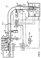
- the pneumatic delivery system 30 includes the tube 26 of generally circular cross-section, which extends from the vault or beverage storage unit 25 within the store building 15, and the beverage dispensing unit 20 at the gas pump island 16.
- a carrier 31 which, during normal operation of the pneumatic delivery system 30, is not removable from the tube 26, although the carrier 31 may be removed from the tube 26 by way of a service door (not shown) in the tube 26 at one or more locations along the tube 26.
- the tube 26 has a single loading end 32 at the vault 25 and a single discharge end 33 at the dispensing unit 20, with only one carrier 31 per tube 26, although more than one such tube 26 may be provided to connect the vault 25 with more than one dispensing unit 20 at different outdoor or other locations.
- the storage unit 25 may be provided with a reloading access door 125 that is accessible from outside of the building 15 to permit restocking by the product distributor without involvement of the operators of the gas station facility 12.
- a storage unit 25 is preferably provided with sensors 126 that may be linked to the inputs of a computer 127 that is programmed to automatically evaluate the stock in the unit 25 and communicate over phone lines 128 with the product distributor, advising that the storage unit 25 at the particular facility 12 is in need of being restocked.
- a pneumatically or electrically operable gate 35 is provided, which is operated in response to a signal from a pneumatic delivery system or conveyor controller 36 to a gate actuator unit 37.
- the gate 35 is moveable between an open position at which a filled beverage container 40 may be loaded from the vault 25 into the carrier 31 and a closed position that will allow a vacuum to be drawn between the gate 35 and the carrier 31 to move an empty carrier 31 from the dispensing unit 20 toward the vault 25.
- a vacuum is applied by a high volume pump 41 being operated at a vacuum.
- the actuator unit 37 may also be provided with valving, a pump or other devices to vent or otherwise control the pressure within the tube 26 immediately inside of the gate 35 to insure the desired motion of the carrier 31 in the portion of the tube between the gate 35 and the pump 41.
- the configuration of the carrier 31, which is illustrated in more detail in Figs. 3A and 3B, may be formed of a cylindrical tubular body 44 formed of metal or hard plastic, which is open at both ends.
- the inside surface of the body 44 is formed of a padded and thermally insulative material 43.
- Within the body 44 is slidably mounted a circular plunger 45.
- the inner surface of the insulative material 43 formed of a material that is adapted to permit the plunger 45 to slide fairly freely but to form at least a moderate air seal with the body 44.
- the plunger 45 is contained within the body by circular stops 46 formed in the opposite ends of the body 44.
- the plunger 45 slides sufficiently freely in the body 44 so as to be drawn to the low pressure side of the carrier 31 and thus locate itself at the leading end of the carrier 31 as the carrier 31 is being pneumatically forced through the tube 26.
- a pair of annular bumpers 47 preferably of a moderately hard rubber or similarly elastic synthetic material.
- the bumpers 47 support the carrier 31 in a low friction slidable contact with the wall of the tube 26 and hold the body 44 in spaced relationship to the wall of the tube 26 to facilitate the movement of the carrier 31 around curves and bends in the tube 26.
- the plunger 45 provides both a seal to facilitate movement of the carrier 31 in the tube 26 and a support for the bottom of the container 40 in the carrier 31.
- the inside surface of the body 44 provides a small amount of friction force to hold a container 40 therein while the carrier 31 is moving, but not so much friction as to interfere with the loading of the container 40 into the carrier 31.
- other elements may be provided to hold the product container 40 in the carrier 31, such as pins or, as illustrated in Figs. 3A and 3B, for example, by spring clips 82.
- a conveyor loading mechanism 50 for feeding beverage containers 40 of any selected one of a number of types from a supply 51 to the input end 32 of the tube 26.
- Any one of a number of retrieving and feeding devices may be provided as the mechanism 50 to drop or robotically retrieve and place the selected container 40 into the open end 32 of the tube 26.
- a drop-shoot vending machine type of dispensing unit is illustrated as the mechanism 50 for simplicity, in which actuators 52 open a door 53 at the bottom of the supply 51 to individually drop one beverage container 40, in accordance with a signal from a loading mechanism controller 55, onto a loading trough 56, with the bottom of the container 40 facing the open end 32 of the tube 26. In this position, a loading ram 57 pushes the container 40 into the carrier 31, also in response to a signal from the controller 55.
- the carrier 31 To be loaded with a container of beverage 40, the carrier 31 must be secured in the position illustrated by the phantom lines 31a in Fig. 2 . In this position, one of the bumpers 47 will rest against a fixed bumper or stop 59 surrounding the opening at the open end 32 of the tube 26, and is of smaller diameter than the tube 26 or the bumpers 47 of the carrier 31 to trap the carrier 31 in the tube 26. In this position, a solenoid actuated locking member 56, which is activated by a signal from the conveyor controller 36, holds the carrier 31 immobile while the container 40 is being loaded into the carrier 31. During loading, of course the gate 35 is open.
- the plunger 45 may be in any position initially, but it will be forced to the end of the carrier 31 that is farthest from the end 32 of the tube 26 by the pushing of the container 40 by the ram 57.
- the carrier 31, with the slidable plunger is symmetrical and, with some tube configurations, can be used in either direction and loaded with containers 40 from either side.
- the tube 26 usually extends horizontally from the vault 25 but may rise or fall somewhat on the way to the location of the dispensing unit 20. Approaching the dispensing unit 20, the tube 26, in the preferred embodiment, changes to a vertical orientation to enter the dispensing unit 20 from the bottom or, as shown in the illustrated embodiment, from the top.
- the discharge end of the tube 26 at the dispensing unit 20 is preferably closed and contains a carrier holding space 60, approximately as long as the carrier 31, that spaces the closed end 33 of the tube 26 from a delivery window 61 in the side of the tube 26.
- a horizontal surface 62 in the form of a counter top covers the dispensing unit 20 and aligns with the boundary between the top of the holding space 60 and the delivery window 61.
- the delivery window 61 faces the customer, for example, toward the window of a vehicle 64 on the access way 17, and is provided with a door or cover 65 that, when in a closed position, pneumatically seals the window 61, as in Fig. 3A, and when in an open position allows a container 40 to be removed from the tube 26, as in Fig. 3B.
- the door or cover 65 may be configured to open and close by vertical movement on the tube 26, or by rotational movement around the tube 26, or by hinged motion or otherwise.
- the opening and closing of the door is achieved by the actuation of a door operating motor 66 in response to a signal from the conveyor controller 36.
- the door 65 may be made of a transparent plastic material, which is particularly desirable if manual opening of the door 65 or manual activation of the door opening actuator 66 is desired.
- an additional high volume pump 68 which is also controlled by signals from the conveyor controller 36.
- the pump 68 operates in cooperation with the pump 41 to move the carrier 31 back and forth between the vault 25 and the dispensing unit 20.
- This pump 68 may be a vacuum pump or may also be capable of operation at positive pressure.
- the pump 68 will operate at a vacuum, at least until the carrier 31 is in a position and moving at a speed sufficient to insure that it will continue to drop by gravity toward the dispensing unit 20.
- the position and speed of the carrier 31 may be verified by the provision of one or more sensors, such as, for example, optical sensor 67 in the wall of the tube 26.
- the pump 68 and/or a pressure control unit 70 which may include one or more valves, vents to atmosphere or pumps, will be operated to insure that some pressure is provided in a sealed space in the tube 26 below the arriving carrier 31 to cushion the arrival of the carrier 31 at the dispensing unit 20, and to bring it to rest gently in the space 60 adjacent the end 33 of the tube 26.
- a locking solenoid 72 is actuated in response to a signal from the conveyor controller 36 to lock the carrier 31 in position in the tube 26 so that the beverage container 40 therein can be unloaded.
- the unloading of the beverage container 40 is accomplished by the movement of a piston 74 of an unloading cylinder 75 that is actuated, also in response to a signal from the conveyor controller 36, as is better illustrated in Figs. 3A and 3B. As illustrated in Fig. 3A, the actuation of the cylinder 75 extends the piston 74 upwardly into contact with the underside of the plunger 45.
- the plunger 45 slides upwardly in the carrier 31, lifting the container 40 upwardly into alignment with the window 61 above the counter surface 62.
- the door opening mechanism 66 is actuated to open the door 65 so that the container 40 can be removed by the customer, as illustrated in Fig. 3B .
- An alternative structure for the pneumatic delivery system 30 may provide for the carrier 31 to have a door or opening in the tubular body 44 for the removal of the contents by the customer, as the carrier 31 presents the product at the dispensing unit 20, as illustrated in Fig. 1B.
- Pneumatic delivery systems that include additional details of systems such as system 30 are well known and may be utilized with the system 30 described herein.
- the operation of the conveyor controller 36 and the loading mechanism controller 55 are coordinated and controlled in response to orders placed by customers on the panel 22 and in response to payments made by way of entry of charge account information into the card reader 18, through a beverage delivery system or main controller 80.
- a beverage delivery system or main controller 80 For example, when a gasoline customer purchases gasoline and inserts a charge card in the card reader 18, a message is displayed asking if an additional purchase of a beverage is desired. If so, an order may be placed by selecting the brand and type of beverage desired by pressing a button on the panel 22. This button selection transmits the beverage order to the main controller 80 which preferably controls the conveyor controller 36 and loading mechanism controller 55 to cause delivery of the product to the customer.
- the controller 80 is also part of the communication circuitry 18a that causes the price of the order to be added to the gasoline charge made through the billing system 19 (Fig. 1) to the account identified by the card read by the card reader 18. If the carrier 31 is in the position 31a indicated by the phantom lines near the loading end 32 of the tube 26 in Fig. 2 , the gate 35 is opened, the loading mechanism controller 55 is signaled by the controller 80, which causes the controller 55 to activate the appropriate actuator 52 to open the door 53 to drop the selected beverage in its container 40 into the trough 56. Thereupon, the controller 55 energizes the cylinder 57 to push the dropped container 40 from the trough 56 into the carrier 40. When the controller 80 determines that the container 40 has been loaded into the carrier 31, through feedback signals from the controller 55 or through additional sensors (not shown) that may be provided, the conveyor controller 36 is signaled to initiate the transporting of the loaded carrier 31 to the dispensing station 20.
- the transporting of the carrier 31 to the dispensing station or unit 20 begins with the assurance that the door 65 that covers the window 61 is closed and that the pressure control unit 70 is set to insure that the lower end of the tube 26 is sealed. Then the pump 68 is energized. The gate 35 will remain open at this time or there will be other openings to allow a venting of atmosphere to the vault side of the carrier 31. This will cause the carrier to be drawn through the tube 26 toward the pump 68. When the carrier 31 has reached the vicinity of the sensor 67 and is moving sufficiently to cause it to reach the vertical section of the tube 26, the pump 68 is turned off, allowing the carrier 31 to free fall.
- the piston 74 is actuated to lift the container 40 on the plunger 45 to the window 61, the door 65 covering the window 61 is opened, and the beverage container 40 is removed.
- the door 65 is closed, the gate 35 at the upper end of the tube 26 is closed, the pressure control 70 is actuated to vent the lower end 33 of the tube 26 to atmosphere, and the motor 41 is operated to apply a vacuum to the tube 26.
- the vacuum in the tube 26 first draws the plunger 45 to the top of the carrier 31 where it rests against the stop 47.
- the pressure differential on the plunger 45 causes the carrier 31 to be forced upwardly in the tube 26 toward the pump 41.
- Pump 41 is turned off as the carrier 31 approaches, allowing the carrier to continue toward the stop 59 at the end 32 of the tube 26. At this position, the carrier 31 may be stored to await another order.
- the system of the present invention can also be used without a separate carrier 31, but rather with the packaging container such as the beverage container 40 serving the function of the carrier 31.
- the packaging container such as the beverage container 40 serving the function of the carrier 31.
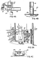
- container 40a blow molded plastic beverage bottles and other reasonably shatter resistant containers, as for example, container 40a, as illustrated in Fig. 4A, which shows the container 40a being loaded directly into the tube 26 at the loading end 32 of the pneumatic system 30 by actuation of the plunger 45.
- the internal cross-section of the tube 25 must match the external cross section of the container 40a.
- the tube 26 is configured to accept standard packaging containers, which, in a bottled beverage vending system, is usually the round cross-section of a beverage bottle.
- Fig. 4B illustrates beverage container 40a at a dispensing unit 20a at the discharge end 33 of the pneumatic system 30.
- a pneumatic system may include the air cushion decelerating feature as described above or some other structure to slow the container 40a upon its arrival at the dispensing unit 20a.
- Fig. 4C illustrates a food packaging container 40b, such as a plastic tubular can with a wide lid at one end, that is of the same exterior cross section as the plastic beverage container 40a which is illustrated in Figs. 4A and 4B.
- the container 40b may be provided a sandwich 91, which may be delivered heated when selected by a customer.
- some sort of heating unit such as a warmer that stores the product in heated condition, or microwave unit that heats the product in response to an order.
- the sandwich may be a cold sandwich that is stored under refrigeration.
- the food product is dispensed and then loaded in its warmed or refrigerated condition into the tube 26 in the same manner as a beverage is loaded, as described above.
- a frozen product such as ice cream or some other food product may be similarly provided.
- Such product may be placed in the container 40b in a plastic film or paper wrapping or with such other packaging material as is necessary to insure its safe delivery through the tube 26.
- Such food items are preferably maintained in a prepackaged condition in such container 40b in the storage unit 25.
- the container 40a or 40b be shaped so as to form two annular bumper rings 47a and 47b, as illustrated in Fig. 4D, and included in the systems illustrated in Figs. 5A-5C, described below.
- the rings 47a,47b serve a tube sealing function similar to that of the bumpers 47 of the carrier 31 in the embodiments of Figs. 2, 3A and 3B.
- the rings 47a,47b have outside diameters that are slightly smaller than, but approximately in conformity with, the internal cross-sectional diameter of the tube 56.
- the cross-section of a central portion 97 of the containers 40a,40b that extends between the rings 47a,47b should be recessed at least by a radius of curvature 98 that is nominally less than, and generally falls within an envelope 98a defined by the inside curvature limit of the sharpest bends of the inside of the tube 56, as illustrated in Fig. 4E .
- the end portions 99 of the container 40a,40b should also fall within an envelope 98b defined by the outside curvature limit of the sharpest bends of the tube 56.
- two annular rings 47a,47b are shown on each of the containers 40a,40b of Fig. 4D , other configurations are acceptable, such as providing the center bottle 40a in Fig. 4D with only one ring, such as ring 47b, or to make the container 40a generally barrel shaped, where the "ring" is the widest cross-section of the container 40a that permits the container to move without binding around the curved sections of the tube 56.
- FIG. 4D Various forms of the beverage containers 40a and food containers 40b are illustrated in Fig. 4D.
- These containers 40a,40b may be formed of a blow molded plastic or in such other manner as are formed plastic soft drink bottles or other preferably plastic containers for food and the packaging of merchandise.
- the rings 47a,47b and the sections 97 and 99 of the container bodies respectively between the rings and at the ends are formed integrally of the molded wall of the container 40a,40b.
- the maximum diameter of the container 40 can be closer to that of the diameter of the tube 56, thus producing a better seal that enables a greater pressure differential to be maintained across the container 40 moving through the tube 56. With greater pressure differential maintained, the container moves more effectively through the tube 56 and is less likely to bind and rattle in the tube as a result of the more effective pneumatic force on the container.
- the ring sections 47 are the closest portions of the containers 40 to the inside of the wall of the tube 26, generally slidably supporting the container in the tube.
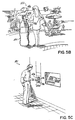
- a system 10a is illustrated in which the pneumatic system 30 thereof has its dispensing unit 20b at the check-out lane of a super market.
- Such a system 10a may charge the purchase of a purchased item, such as a beverage carried in a container 40a, to a grocery order being accounted for at a check-out counter 95.
- Such a system 10a may charge the purchase of an purchased item, such as a beverage carried in a container 40a, to a grocery order being accounted for at a check-out counter 95.
- the beverage container 40a utilizes a container wall configuration employing the annular seal structure 47a and 47b, discussed in connection with Figs. 4D and 4E, above.
- a dispensing unit 20c is provided in a system 10b at a recreational location such as a swimming pool or swimming club.
- a dispensing unit 20c may contain its own charge card reader or, where at a membership facility or the like, accept a member code and charge the item to the member's account.
- Fig. 5C illustrates an example of a dispensing unit 20d of a system 10c that may be preferably associated with a device such as an automated teller machine or other accounting system at which an account of a customer is identified to facilitate a purchase.
- a device such as an automated teller machine or other accounting system at which an account of a customer is identified to facilitate a purchase.
- Fig. 5D illustrates a system 101 employing principles of the invention in a hotel for replacing a hotel room minibar system or other room supply or delivery system
- a pneumatic delivery system delivers food and beverages, towels or personal items to the guests' rooms in response to commands entered by the hotel guest on a data entry device, such as by use of a television set remote controller to select items from a menu displayed on a television screen in the guest's room.
- a system 101 includes a remote storage unit 102, similar to those described in the systems above, selectively connected through a pneumatic delivery system 103 with each of a plurality of guest rooms 104.
- a delivery terminal 105 In the rooms 104 is situated a delivery terminal 105 to which the container carrying the beverage or other product or item is presented to the room guest.
- the room guest selects the item desired from a menu displayed on the screen 106 of the cable television set 107 in the guest room 104, preferably by entering a menu item code on the channel selector of the television remote controller 108.
- the command signals are communicated through the television cable connection 109 to hotel office 110 and billing equipment located thereat, which includes circuits programmed to operate automated product selection and loading equipment 111 at the storage unit.
- the order commands originating from the guest rooms 104 are identified with the rooms 104 from which the commands originated, and therefore the products ordered may be automatically charged to the guest's room or account.
- the guest is out of the room 104 and in another part of the hotel, such as at the swimming pool 115, on a golf course or tennis court or other recreational facility 116 of a resort hotel, in an exercise room 117, or in the hotel lobby, a hall or conference area 118
- use of the system to order beverages or other products may result in a charge to the guest's room by the provision of a code entry device such as a key card reader 119, at dispensing terminals 20e, which condition the operation of the system on the entry of a personal identity number or insertion of a machine readable room key card to identify the guest and the guest room account to which the item is to be charged.
- the storage unit may also be provided with a loading port 112 for accepting special food containers 40c manually loaded with food items comparable to room service items prepared by the hotel kitchen 113 in response to the orders entered by the guest in the rooms 104.
- the system 101 may be similarly provided with a loading port 120 for accepting custom mixed drinks in fillable beverage containers 40d at the hotel bar area 122.
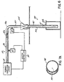
- Fig. 6 illustrates a product delivery or dispensing unit, such as unit 20b, configured in an embodiment that is an alternative to that of Figs. 3A and 3B, particularly with respect to a product decelerating device 100.
- a product supply enclosure or vault 25 that contains the product supply and loader is connected to the inlet end of tube 26 of the pneumatic conveyor system 30.
- Vacuum pumps 41 and 68 are connected to the tube 26 at upstream and downstream portions thereof, respectively.
- the product loader and supply 25 and pumps 41,68 are shown connected to output lines of the system controller 80.
- the delivery end of the conveyor 30 includes the decelerating device 100 connected to the downstream or outlet end of the tube 26 and extends into the dispensing or delivery unit 20b of the customer terminal.
- the device 100 includes a passive bypass valve 125 connected in the tube 26 downstream of the downstream pump 68, preferably in a vertically downwardly descending section 127 of the tube 26. In this section 127, a product will be moved by gravity through the tube 26 toward the dispensing unit 20b, in absence of a pneumatic pressure differential across the product.
- the valve 125 includes a chamber 128 of generally rectangular horizontal cross-section and having a wide upper portion 131, a narrow lower portion 132, and a tapered central portion 133 having generally inclined side walls 134.
- the chamber 128 is centered and in vertical alignment with an inlet port 135 at the top of the chamber 128 and connected to the tube 26, and a lower port 136 connected to and in vertical alignment with a vertical delivery section 140 of the tube 26.
- Within the chamber 128 are a pair of opposed flap valve members 141 and 142, each pivotally connected at the bottom ends 138 thereof to the wall of the chamber 128 immediately above the lower port 136 of the valve 125.
- the members 141,142 have an angle formed in the center thereof that is the same as the angle 144 between the side vertical walls of the lower chamber section 132 and the tapered walls 134 of the central chamber portion 133. So shaped, the members 141,142 will conform to and lie against the walls of the chamber 128 when the valve 125 is open, as illustrated in Fig. 7B.
- a bypass tube 150 is connected between one of the sloped walls 134 of the chamber 128 and the bottom 151 of the tube delivery section 140.
- the bypass tube 150 includes a section 152 of round cross-section which connects to a crescent shaped section 153 appended to the back of the delivery section 140 of the tube 26, as illustrated in Fig. 7A, opposite the product removal gate or window 61 in the dispensing or delivery unit 20b.
- the pressure within the delivery tube 140 remains at nearly atmospheric pressure until a container 40a is moved through the tube 26 and into the vertical portion 127, where, by its own momentum and the force of gravity, it pushes air before it, facilitated by the sealing action of the annular rings 47a,47b formed in the container 40a.
- the air pushed or pumped by the moving container 40a passes through vent holes 155 in the upper segments of the members 141,142 and through the bypass tube 150, and into the bottom 151 of the tube section 140.
- a cylindrical floating plunger-like head 160 that is vertically slidable within the tube, but forms a generally effective seal with the cylindrical wall of the tube 140.
- the floating head 160 normally rests against a retaining grid 161 near the bottom end 151 of the tube delivery section 140.
- the members 141,142 are provided with bias springs 163, at the pivot points 136 that are sufficiently strong to hold the members together, as illustrated in Fig. 7 , against any pressure differential that may develop by the air flowing across the vent holes 148 as the container 40a approaches the valve 125.
- the head 160 is sufficiently moveable in the tube 140 so as to move upwardly, as indicated by arrow 162, in the tube 140, as pressure develops through holes 155 and bypass tube 152 at the bottom of the tube 140 below the floating head 160, lifting the head 160 against the atmospheric pressure in the tube 140 above the head 160 due to the venting through holes 148 to the outer ambient pressure environment.
- the tapered wall portions 134 of the valve 125 include a pair of stopper pads 164, which are positioned to close the holes 155 in the members 141,142 as the members pivot against the pads 164, as illustrated in Fig. 7B.
- the members 141,142 are cammed apart, bringing the holes 155 into contact with the pads 164, sealing the bypass tube 150 from the top.
- the head 160 will have moved against a stop ring 166 immediately below the holes 148 near the lower valve port 136.
- the container 40a continues to move downwardly against the head 160, supported on the air pressure beneath the plunger or head 160 in the tube section 140, causing the head 160 to move downwardly against the pressure in the tube section 140 while decelerating the container 40b.
- the members 141,142 are urged together and away form the pads 164, thus opening the holes 155, and allowing the air in the tube 140 to escape through the bypass tube 150, permitting the pressure to be drop on the underside of the head 160.
- the container 40a thereupon gently descends as the head 160 gently settles against the grid stop 161 below the window 61, presenting the product in its container 40a at the window 61 for removal by the customer, as illustrated in Fig. 7C .
- the deceleration device 100 and the containers 40a and 40b having the integral annular seals 47a,47b facilitate the automatic pneumatic delivery of beverages and other food products, and other products such as those that would be damaged by less gentle handling than described above.
- the deceleration device 100 derives the energy needed to develop back-pressure ahead of the container 40 arriving at the customer terminal from the kinetic energy of the moving product in the tube 26, which pressure is used to slow and stop the container. In the preferred embodiment described above, this is achieved positively and reliably by the use of a passively controlled mechanical valve 125, that is activated by contact by the moving container 40.
- a sensor could be employed to detect the arrival of the container 40 at the valve 125 and the valve could then be actively controlled by energizing a solenoid, pneumatic cylinder or other element to cause the valving to be affected to route the pressurized air through the backup tube 150 and to seal off the tube 150 at the proper times.
- a separate air supply could be employed to develop the back-pressure, rather than using the moving container to provide the pressurized air.
- using the container 40 to develop the back-pressure removes energy form the moving container and thus contributes to the deceleration of the product.
- a gate-type valve 175 can be used, as illustrated in Fig. 8 , and activated to block the tube behind a container 40 as the container passes, thereby creating a vacuum behind the advancing container 40 to provide the a negative pressure to brake the motion of the container 40.
- the members 141,142 are configured to have a sealing effect when in contact with each other and between their edges and the parallel end walls of the chamber 128, thereby facilitating the development of a vacuum in the space 176 between the members 141,142 and the product in the container 40.
- a tighter fit of the container 40 with the wall of the tube 26 will inhibit low friction motion of the container 40 through the tube 26 and will restrict the ability of the container 40 to round the bends of the tube.
- the tighter fit between the tube 26 and the plunger 160 provides more effective and predictable braking of the motion of the container 40, thus avoiding occasionally excessive impact of the product at the final stop 161 due to insufficient deceleration or bouncing of the product due to too much deceleration.
- the preferred embodiment presents a passive deceleration device, which is reliable, economical and easy to control.
- a product such as a beverage in a container 40a in the form of a plastic beverage bottle , for example, will move through tube 26 under a pressure gradient in the downstream direction imposed by vacuum pump 68, as illustrated in Fig. 6 .
- the product will pass around a bend or curved portion 26a of the tube 26, with the annular ring portions 47 of the bottle 40a permitting the bottle to move freely around the bend and through the tube while maintaining effective sealing contact with the wall of the tube 26.
- a sensor may signal the controller 80 to turn off the motor 68.
- the beverage filled container 40a will then proceed, under its own momentum and under the pull of gravity, downward in the tube 26, as illustrated in Fig. 7. So moving, the kinetic and gravitational energy of the moving container is partially expended against the pressure of the air in the tube beneath the container 40a, increasing the pressure below the container 40a in the tube 26. At this point the members 141,142 of the valve 127 are closed and the disc 160 is resting on the grid stop 161 in the lower portion 140 of the tube 26.
- the disc 160 moves toward and against the stop ring 166 as the container 40a approaches the top of the valve 125, as the pressure below the container 40a and below the disc 160 approaches a maximum, as illustrated in Fig. 7B.
- the container 40a As the container 40a enters the valve 125, it contacts the upper portion of the members 141,142, camming them apart, also as illustrated in Fig. 7B, causing the pads 164 to block the holes 148, trapping the air in the bypass tube 150 and in the space in the tube 140 below the disc 160, as the container 40a contacts the disc 160.
- the disc 160 with the pressurized air beneath it, thereupon elastically increases to a maximum force on the bottom of the container 40a, which increases the deceleration of the container 40a, as the container 40a continues to move downward.
- the members 141,142 move together under the force of springs 163, opening the holes 155 into the valve 125 and the upper portion of the tube 26. This gradually reduces the pressure in the lower portion 140 of the tube 26 and allows the disc 160 to gently lower the container 40a onto the stop grid 161, presenting the beverage product in its container 40a at the window 61 of the customer terminal 20b.
Landscapes
- Engineering & Computer Science (AREA)
- Architecture (AREA)
- Physics & Mathematics (AREA)
- General Physics & Mathematics (AREA)
- Civil Engineering (AREA)
- Structural Engineering (AREA)
- Control Of Vending Devices And Auxiliary Devices For Vending Devices (AREA)
- Management, Administration, Business Operations System, And Electronic Commerce (AREA)
- Vending Machines For Individual Products (AREA)
- Beverage Vending Machines With Cups, And Gas Or Electricity Vending Machines (AREA)
- Financial Or Insurance-Related Operations Such As Payment And Settlement (AREA)
- Cash Registers Or Receiving Machines (AREA)
- Loading And Unloading Of Fuel Tanks Or Ships (AREA)
- Warehouses Or Storage Devices (AREA)
- Feeding And Watering For Cattle Raising And Animal Husbandry (AREA)
Abstract
Description
Claims (12)
- A system (11) for vending individually packaged products (40, 40a, 91) comprising an order entry device (22, 108) operable to cause generation of an order command in response to an order input from a customer, a product dispensing unit (20-20e, 105) operable to present a product (40, 40a, 91) in its packaging container to the customer, a product supply terminal (25, 29, 51, 102), a pneumatic conveyor (30) extending between the product supply terminal and the product dispensing unit (20-20e, 105) operable, when activated, to move an individually packaged product (40, 40a, 91) in its packaging container from the supply terminal (25, 29, 51, 102) to the dispensing unit (20-20e, 105), a product loading mechanism (50, 111), and a controller (80) operable to activate the conveyor (30) and the product loading mechanism (50, 111) in response to an order command, operably connected with the product supply terminal (25, 29, 51, 102) and the pneumatic conveyor (30) and operable when activated to load, from the supply, a product (40, 40a, 91), in its container, to the pneumatic conveyor (30), characterised in that the controller (80) is logically linked to a payment device (18, 19, 23) that accepts payment for the product or charges payment therefor to the customer; in that the order entry device (22, 108), payment device (18, 19, 23) and product dispensing unit (20-20e, 105) are provided remotely located from the product supply terminal (25, 29, 51, 102) across an intermediate space sufficient to contain a pedestrian or vehicle access lane (17); in that a diverse article support or conveyor or a space divider, partition or thermal barrier, separates the product supply terminal (25, 29, 51, 102) from the order entry device (22, 108), payment device (18, 19, 23) and product dispensing unit (20-20e, 105), and in that the pneumatic conveyor (30) extends past the intermediate space to the product dispensing unit (20-20e, 105).
- A system as claimed in Claim 1 wherein the system is in combination with a gasoline vending system (12) at a gasoline service facility having a gasoline service island (16) which includes a gasoline pump (13) and a credit card reader (18), the payment subsystem is a credit card billing subsystem (19) interconnected with the pump (13) and to the credit card reader (18) to automatically charge gasoline purchases to a charge account of the customer, the order entry device (22) and dispensing unit (20) are located at a gasoline service island (16), and the payment device (18) includes connections to the billing subsystem (19) of the gasoline vending system (12) to automatically charge a purchase of the vended packaged product (40, 40a, 91) to the charge account of the customer.
- A system as claimed in Claim 1 wherein the system is a diverse vending system (11) at a product retail facility having a check-out lane thereat, the payment subsystem including a cash register located at the check-out lane receiving payment from the customer for products (40a) vended through the diverse vending system (11), the order entry device (22) and dispensing unit (20b) located at the check-out lane, and the payment device includes connections to the cash register to automatically post a charge for the purchase of the vended packaged product (40a) to a total at the cash register.
- A system as claimed in Claim 1 wherein the system is a diverse vending system (11) having a payment subsystem by which charges are posted to customer accounts of its customers, the product supply unit (25, 29, 51, 102) is provided at a central location in the facility, the order entry device (22) and product dispensing unit (20-20e, 105) are provided in a location accessible to customers of the facility, and the payment device is provided with a communication link connecting the order entry device (22) with the payment subsystem of the facility and includes means for identifying a customer account of a customer of the facility.
- A system as claimed in any preceding Claim wherein the order entry device (22) includes a product selector operative to generate a product selection command in response to a product selection by the customer, the supply terminal (25, 29, 51, 102) is configured to store a plurality of supplies of different products (40, 40a, 91), and the product loading mechanism (50, 111) is operable, when activated, to selectively load a product (40, 40a, 91) from one of the supplies to the conveyor (30) in accordance with the product selection command.
- A system as claimed in any preceding Claim wherein the pneumatic conveyor (30) includes a reusable hollow carrier (31, 40b, 40c) moveable therein adapted to enclose a product (40, 40a, 91) therein for transfer from the product supply terminal (25, 29, 51, 102) to the product dispensing unit (20-20e, 105), and the pneumatic conveyor (30) being operative, when activated, to apply a pneumatic pressure across the carrier to move the carrier from the product supply terminal to the product dispensing unit (20-20e, 105).
- A system as claimed in any preceding Claim further comprising a product delivery tube (26) extending from the product supply terminal (25, 29, 51, 102) and the product dispensing unit (20-20e, 105), a deceleration device (100) at the product dispensing unit including a floating element (160) slidably mounted in, and forming a slidable seal with, the tube (26), and means for developing pneumatic back-pressure behind the floating element to decelerate a product (40, 40a, 91) moving thereagainst.
- A method of use of a system of any preceding Claim comprising loading a product (40, 40a, 91) packaged in a packaging container into the pneumatic conveyor (30) from the product supply terminal (25, 29, 51, 102) in response to an order entered through the order entry device (22), and then moving the product with pneumatic pressure from the product supply terminal (25, 29, 51, 102) to the product dispensing unit (20-20e, 105).
- A method as claimed in Claim 8 of use of a system as claimed in Claim 4, wherein the loading and moving steps include the steps of processing an order entered by a customer on the order entry device (22), pneumatically delivering an ordered product (40, 40a, 91) to the dispensing unit (20-20e, 105) and charging the price of the delivered product to a customer account of the customer entering the order.
- A method as claimed in either Claim 8 or Claim 9 wherein the order entry device (22) and product dispensing unit (20-20e, 105) are provided in an ambient temperature environment, and the loading step includes the steps of maintaining the product (40, 40a, 91) at a non-ambient temperature, and loading the temperature maintained product into the pneumatic conveyor (30).
- A method as claimed in any of Claims 8 to 10 wherein the pressure providing step includes the step of applying differential pressure directly across the packaging container of the product (40, 40a, 91) and thereby moving the product without a carrier in its packaging container to the product dispensing unit (20-20e, 105).
- Use of a system as claimed in any of Claims 1 to 7 or a method as claimed in any of Claims 8 to 11 wherein the product is food product (40, 40a, 91).
Applications Claiming Priority (9)
| Application Number | Priority Date | Filing Date | Title |
|---|---|---|---|
| US40424395A | 1995-03-15 | 1995-03-15 | |
| US404243 | 1995-03-15 | ||
| US449935 | 1995-05-25 | ||
| US08/449,935 US5586686A (en) | 1995-03-15 | 1995-05-25 | Temperature maintained food dispensing system and method |
| US571253 | 1995-12-12 | ||
| US08/571,253 US5725124A (en) | 1995-03-15 | 1995-12-12 | Product vending and pneumatic delivery system and method |
| US08/571,252 US5816443A (en) | 1995-03-15 | 1995-12-12 | Product vending system with pneumatic product delivery |
| US571252 | 1995-12-12 | ||
| PCT/US1996/003590 WO1996028279A1 (en) | 1995-03-15 | 1996-03-15 | Product vending system with pneumatic product delivery |
Publications (3)
| Publication Number | Publication Date |
|---|---|
| EP0759832A1 EP0759832A1 (en) | 1997-03-05 |
| EP0759832A4 EP0759832A4 (en) | 1998-07-08 |
| EP0759832B1 true EP0759832B1 (en) | 2002-07-03 |
Family
ID=23598784
Family Applications (1)
| Application Number | Title | Priority Date | Filing Date |
|---|---|---|---|
| EP96911323A Expired - Lifetime EP0759832B1 (en) | 1995-03-15 | 1996-03-15 | Product vending system with pneumatic product delivery |
Country Status (19)
| Country | Link |
|---|---|
| US (1) | US5586686A (en) |
| EP (1) | EP0759832B1 (en) |
| JP (1) | JPH10512719A (en) |
| CN (1) | CN1077480C (en) |
| AT (1) | ATE219987T1 (en) |
| AU (1) | AU700275B2 (en) |
| BG (1) | BG100973A (en) |
| CA (1) | CA2189768C (en) |
| CZ (1) | CZ335296A3 (en) |
| EE (1) | EE9600204A (en) |
| HU (1) | HUP9603098A3 (en) |
| LT (1) | LT4220B (en) |
| LV (1) | LV11794B (en) |
| NO (1) | NO964840L (en) |
| PL (1) | PL180033B1 (en) |
| RO (1) | RO115029B1 (en) |
| RU (1) | RU2155990C2 (en) |
| SK (1) | SK144196A3 (en) |
| WO (1) | WO1996028279A1 (en) |
Families Citing this family (67)
| Publication number | Priority date | Publication date | Assignee | Title |
|---|---|---|---|---|
| USH1743H (en) * | 1995-03-17 | 1998-08-04 | Hercules Incorporated | Inventory management method and apparatus |
| US5805454A (en) * | 1995-08-10 | 1998-09-08 | Valerino, Sr.; Fred M. | Parenteral products automation system (PPAS) |
| US20010056311A1 (en) * | 1997-09-25 | 2001-12-27 | Fred M. Valerino | Automatic empty carrier storage, retrieval and distribuition system |
| NO310816B1 (en) * | 1998-06-05 | 2001-09-03 | Zopa As | Closed transport system for refrigerated products |
| US6401009B1 (en) | 1999-02-16 | 2002-06-04 | Suzette M. Chandonnet | Sundry article vending apparatus |
| US6424884B1 (en) * | 1999-03-03 | 2002-07-23 | The Coca-Cola Company | Vending machine with transponder interrogator |
| US6167711B1 (en) | 1999-04-16 | 2001-01-02 | Restaurant Technology, Inc. | Sanitized ice transportation system and method |
| NO316373B1 (en) * | 1999-12-03 | 2004-01-19 | Zopa As | Transportsystem |
| US6527176B2 (en) | 2000-03-31 | 2003-03-04 | Robert Baric | Collective payment and control system |
| NO20003637L (en) * | 2000-07-14 | 2002-01-15 | Zopa As | Device for conveying products |
| NO311460B1 (en) * | 2000-07-14 | 2001-11-26 | Zopa As | Method and apparatus for cooling products in a transport system |
| US7185809B2 (en) * | 2001-01-12 | 2007-03-06 | Wm. Wrigley Jr. Company | RF point of purchase apparatus and method of using same |
| US20020095343A1 (en) * | 2001-01-12 | 2002-07-18 | Barton Steven P. | Apparatus and method for providing point of purchase products |
| US20050080679A1 (en) * | 2001-01-12 | 2005-04-14 | Barton Steven P. | Method for generating revenue with a product dispensing device |
| US20050167489A1 (en) * | 2001-01-12 | 2005-08-04 | Barton Steven P. | Point of purchase dispensing device with container and method of using same |
| DE10121321C2 (en) * | 2001-05-02 | 2003-03-20 | Leonhard Hobmaier | Order facility for fast food restaurants |
| US6976353B2 (en) * | 2002-01-25 | 2005-12-20 | Arvin Technologies, Inc. | Apparatus and method for operating a fuel reformer to provide reformate gas to both a fuel cell and an emission abatement device |
| NO20020585L (en) * | 2002-02-05 | 2003-08-06 | Zopa As | System and method for transferring products from a storage area to a delivery area |
| USD513022S1 (en) | 2002-02-05 | 2005-12-20 | Zopa As | Transfer unit |
| US20040050855A1 (en) * | 2002-09-17 | 2004-03-18 | Gordon Jurgenson | Vending machine |
| US7343006B2 (en) * | 2003-09-25 | 2008-03-11 | Americas's Drive-In Corp. | Drive-in restaurant credit-card transaction system |
| FR2870024B1 (en) * | 2004-05-07 | 2008-04-18 | Kiala Sa | TERMINAL AND SERVER FOR THE MANAGEMENT OF AN EXCHANGE OF PRODUCTS IN A PRODUCT DELIVERY POINT |
| US7568618B1 (en) * | 2005-03-01 | 2009-08-04 | Gfc Automat, Inc. | Automated food service and billing system and method |
| AT502157B1 (en) * | 2005-03-21 | 2007-05-15 | Schiestl Josef | GOODS MACHINE |
| US20060229891A1 (en) * | 2005-04-06 | 2006-10-12 | Ryko Manufacturing Company | Drive-up dispensing device for car wash facility |
| WO2006130009A1 (en) * | 2005-05-02 | 2006-12-07 | Oppie Design As | System and use of a system; particularly a minibar, with centrally controlled product purchase |
| US20070299724A1 (en) * | 2005-06-23 | 2007-12-27 | Hales Walter Jr | Apparatus and method of marketing products, distributing product samples and capturing consumer personal data |
| US7469826B2 (en) * | 2005-10-31 | 2008-12-30 | The Kroger Co. | Combined in-store and fuel center point-of-sale system |
| US20090108015A1 (en) * | 2007-10-30 | 2009-04-30 | David Kreamer | Combination ATM/Vending Machine Kiosk |
| CN101642342B (en) * | 2008-07-02 | 2015-09-09 | 北京银融科技有限责任公司 | Catering system and manufacturing method thereof |
| RU2411582C2 (en) * | 2009-02-03 | 2011-02-10 | Поль Эмануилович Бланк | Trade system |
| US9105144B2 (en) | 2010-01-12 | 2015-08-11 | Robert J. Baric | Multiple-sided vending machine |
| US9098959B2 (en) * | 2010-01-12 | 2015-08-04 | Robert Baric | Multi-sided vending machine |
| US8156013B2 (en) | 2010-06-28 | 2012-04-10 | Amazon Technologies, Inc. | Methods and apparatus for fulfilling tote deliveries |
| US8219463B2 (en) * | 2010-06-28 | 2012-07-10 | Amazon Technologies, Inc. | Methods and apparatus for returning items via a tote delivery service |
| US8266017B1 (en) | 2010-06-28 | 2012-09-11 | Amazon Technologies, Inc. | Methods and apparatus for providing recommendations and reminders to tote delivery customers |
| US8266018B2 (en) | 2010-06-28 | 2012-09-11 | Amazon Technologies, Inc. | Methods and apparatus for managing tote orders |
| US8175935B2 (en) * | 2010-06-28 | 2012-05-08 | Amazon Technologies, Inc. | Methods and apparatus for providing multiple product delivery options including a tote delivery option |
| JP4764952B1 (en) * | 2010-10-27 | 2011-09-07 | プロパティエージェント株式会社 | In-building service system |
| US9811784B2 (en) | 2012-03-29 | 2017-11-07 | Amazon Technologies, Inc. | Modular station pickup locations |
| US9230230B2 (en) | 2012-03-29 | 2016-01-05 | Amazon Technologies, Inc. | Pickup location monitoring |
| MX343794B (en) * | 2012-03-29 | 2016-11-23 | Amazon Tech Inc | Pickup locations. |
| US9830572B2 (en) | 2012-03-29 | 2017-11-28 | Amazon Technologies, Inc. | Pickup locations |
| FI125741B (en) * | 2012-07-02 | 2016-01-29 | Maricap Oy | Method and apparatus for handling materials in a pneumatic material handling system |
| US9934483B1 (en) | 2013-08-06 | 2018-04-03 | Amazon Technologies, Inc. | Off network return operations for pickup locations |
| US10354476B2 (en) * | 2014-11-03 | 2019-07-16 | Jayce Jones | Product vending and tube delivery system for delivering products to remote consumers |
| SE538965C2 (en) * | 2015-04-24 | 2017-03-07 | Sps Smart Pipe Systems Ab | A guiding member, a system for guiding objects by means of said guiding member and a method |
| RU174365U1 (en) * | 2015-11-09 | 2017-10-11 | Олег Сергеевич Синюхин | AUTOMATED ITEM OF STORAGE AND SELF-DELIVERY OF GOODS |
| RU2657414C2 (en) * | 2016-05-11 | 2018-06-13 | Виталий Владимирович Бакалейко | Method for manufacturing tank shell for water vending machine |
| FR3056200B1 (en) * | 2016-09-16 | 2018-11-23 | Vinci Construction | BURNER SYSTEM FOR DISTRIBUTION OF GOODS IN URBAN ENVIRONMENT |
| CN106744618A (en) * | 2016-12-16 | 2017-05-31 | 常德新三湘能源有限公司 | A kind of monoblock type gas station stood behind preceding shop |
| US10490014B2 (en) | 2016-12-16 | 2019-11-26 | Pepsico, Inc. | Lean vending machine |
| CN107578564A (en) * | 2017-10-19 | 2018-01-12 | 西安工业大学 | A kind of liquid food automatic packaging vending machine |
| CN107705434A (en) * | 2017-11-03 | 2018-02-16 | 孙庆玲 | The Special Automatic vending machine of train and application method with ticket sale system |
| EP3740442B1 (en) * | 2018-01-17 | 2024-03-13 | Rxsafe Llc | System and method for dispensing orders |
| RU2706615C2 (en) * | 2018-03-30 | 2019-11-19 | Сергей Анатольевич Брюханов | Postal transport system on magnetic suspension, device of switchover of this system, device of its point of loading and unloading, device of vertical switch unit of this system |
| CN109516212A (en) * | 2018-11-21 | 2019-03-26 | 中铁第四勘察设计院集团有限公司 | A kind of Cold Chain Logistics conduit pipe pneumatically acceleration and deceleration system and method |
| WO2021046584A1 (en) * | 2019-09-05 | 2021-03-11 | The Wilkinson Group Llc | Baked product kiosk |
| SE2050744A1 (en) * | 2020-06-23 | 2021-12-24 | Omniloop Ab | Tube-carrier based logistics system and method for performing logistics services with such system |
| RU2743627C1 (en) * | 2020-07-08 | 2021-02-20 | Вадим Исаакович Коган | System of rapid remote sales of goods and rendering services |
| US11462072B2 (en) | 2020-08-18 | 2022-10-04 | Dov Z. Glucksman | Autonomous food station |
| US12536860B2 (en) | 2020-08-18 | 2026-01-27 | T3 Micro, Inc. | Autonomous food station |
| US11776351B2 (en) | 2020-08-18 | 2023-10-03 | Kent Yu | Autonomous food station |
| US11605260B2 (en) | 2020-08-18 | 2023-03-14 | T3 Micro, Inc. | Autonomous food station |
| RU2755369C1 (en) * | 2021-03-12 | 2021-09-15 | Сергей Анатольевич Брюханов | Pipeline maglev cargo transport system |
| CN117940974B (en) * | 2021-07-05 | 2025-12-30 | 福瑞托-雷北美有限公司 | Automatic product dispenser |
| CN113910249B (en) * | 2021-09-10 | 2023-04-07 | 台州恩泽医疗中心(集团) | Parkinson patient is with intelligent meal nutrition management device |
Family Cites Families (22)
| Publication number | Priority date | Publication date | Assignee | Title |
|---|---|---|---|---|
| DE509125C (en) * | 1929-08-18 | 1930-10-04 | Paul Baatz | Procedure for the sale of goods |
| US3647026A (en) * | 1969-12-31 | 1972-03-07 | Gilbert L Alexander | Automatic drive-in store |
| GB1373088A (en) * | 1971-12-31 | 1974-11-06 | Mars Ltd | Beverage-dispensing machines |
| SE371409B (en) * | 1972-08-25 | 1974-11-18 | Svenska Flaektfabriken Ab | |
| US3945682A (en) * | 1974-11-04 | 1976-03-23 | Monsanto Company | Method and apparatus for transferring articles |
| US4073368A (en) * | 1975-01-20 | 1978-02-14 | Mustapick Andrew James | Automated merchandising system |
| DE2510415A1 (en) * | 1975-03-11 | 1976-09-16 | Gernot Lucas | DEVICE FOR TRANSPORTING GOODS, IN PARTICULAR ICE CREAM, FOR USE IN VENDING MACHINES |
| US4111282A (en) * | 1976-08-23 | 1978-09-05 | Vayda Jr Michael Mark | Single-stop shopping facility and method |
| US4284370A (en) * | 1978-11-16 | 1981-08-18 | Danler Richard W | Air conveyor for bottles and bottle preforms |
| JPS5943366B2 (en) * | 1979-06-14 | 1984-10-22 | 川崎製鉄株式会社 | air shooter |
| US4638312A (en) * | 1985-10-25 | 1987-01-20 | Ncr Corporation | Order entry system including an interactive menu display |
| US4675515A (en) * | 1986-03-04 | 1987-06-23 | Lucero James L | Drive-through credit card payment device |
| US4712650A (en) * | 1986-03-28 | 1987-12-15 | Pronto Service Facilities, Inc. | Hood conveying apparatus having an outwardly reaching basket |
| US5113974A (en) * | 1987-08-20 | 1992-05-19 | Mark Vayda | Timed cycle single stop shopping facility |
| JPH02196393A (en) * | 1989-01-26 | 1990-08-02 | Fuji Electric Co Ltd | Commodity selection controller for automatic vending machine |
| JPH02202694A (en) * | 1989-02-01 | 1990-08-10 | Fuji Electric Co Ltd | Vending machine |
| US5020688A (en) * | 1989-05-31 | 1991-06-04 | Power Patrick J | Hot popcorn microwave vending machine |
| US5105979A (en) * | 1989-09-07 | 1992-04-21 | Fri-Jado B.V. | Vending machine |
| RU2013334C1 (en) * | 1990-01-02 | 1994-05-30 | Государственный научно-исследовательский, проектный и конструкторский институт горного дела и металлургии цветных металлов | Pneumatic transport system |
| DE69126247T2 (en) * | 1990-07-06 | 1998-01-08 | Forfas | Method and device for conveying pieces of ice |
| US5158155A (en) * | 1990-10-11 | 1992-10-27 | Vendorsgroup, Inc. | Vendors' structural complex |
| RU2038453C1 (en) * | 1994-07-11 | 1995-06-27 | Савелий Михайлович Каганов | Trading pavilion |
-
1995
- 1995-05-25 US US08/449,935 patent/US5586686A/en not_active Expired - Lifetime
-
1996
- 1996-03-15 CA CA002189768A patent/CA2189768C/en not_active Expired - Fee Related
- 1996-03-15 AT AT96911323T patent/ATE219987T1/en not_active IP Right Cessation
- 1996-03-15 RO RO96-02163A patent/RO115029B1/en unknown
- 1996-03-15 WO PCT/US1996/003590 patent/WO1996028279A1/en not_active Ceased
- 1996-03-15 PL PL96317228A patent/PL180033B1/en unknown
- 1996-03-15 HU HU9603098A patent/HUP9603098A3/en unknown
- 1996-03-15 RU RU96122493/09A patent/RU2155990C2/en active
- 1996-03-15 EP EP96911323A patent/EP0759832B1/en not_active Expired - Lifetime
- 1996-03-15 CN CN96190500A patent/CN1077480C/en not_active Expired - Fee Related
- 1996-03-15 SK SK1441-96A patent/SK144196A3/en unknown
- 1996-03-15 EE EE9600204A patent/EE9600204A/en unknown
- 1996-03-15 JP JP8527849A patent/JPH10512719A/en active Pending
- 1996-03-15 CZ CZ963352A patent/CZ335296A3/en unknown
- 1996-03-15 AU AU54240/96A patent/AU700275B2/en not_active Ceased
- 1996-11-12 LT LT96-157A patent/LT4220B/en not_active IP Right Cessation
- 1996-11-12 BG BG100973A patent/BG100973A/en unknown
- 1996-11-14 NO NO964840A patent/NO964840L/en not_active Application Discontinuation
- 1996-12-09 LV LVP-96-432A patent/LV11794B/en unknown
Also Published As
| Publication number | Publication date |
|---|---|
| CZ335296A3 (en) | 1997-10-15 |
| AU5424096A (en) | 1996-10-02 |
| CA2189768A1 (en) | 1996-09-19 |
| LV11794B (en) | 1998-01-20 |
| CA2189768C (en) | 2006-11-07 |
| PL317228A1 (en) | 1997-03-17 |
| RO115029B1 (en) | 1999-10-29 |
| JPH10512719A (en) | 1998-12-02 |
| SK144196A3 (en) | 1997-08-06 |
| PL180033B1 (en) | 2000-12-29 |
| HUP9603098A2 (en) | 1998-06-29 |
| EP0759832A1 (en) | 1997-03-05 |
| LT4220B (en) | 1997-09-25 |
| NO964840L (en) | 1997-01-10 |
| WO1996028279A1 (en) | 1996-09-19 |
| BG100973A (en) | 1997-06-30 |
| NO964840D0 (en) | 1996-11-14 |
| LV11794A (en) | 1997-06-20 |
| EE9600204A (en) | 1997-06-16 |
| HUP9603098A3 (en) | 2000-08-28 |
| LT96157A (en) | 1997-04-25 |
| US5586686A (en) | 1996-12-24 |
| EP0759832A4 (en) | 1998-07-08 |
| CN1154083A (en) | 1997-07-09 |
| CN1077480C (en) | 2002-01-09 |
| ATE219987T1 (en) | 2002-07-15 |
| AU700275B2 (en) | 1998-12-24 |
| RU2155990C2 (en) | 2000-09-10 |
Similar Documents
| Publication | Publication Date | Title |
|---|---|---|
| CA2189768C (en) | Product vending system with pneumatic product delivery | |
| US5816443A (en) | Product vending system with pneumatic product delivery | |
| US5725124A (en) | Product vending and pneumatic delivery system and method | |
| US6164491A (en) | Pneumatic product vending system and product loader therefor | |
| EP0752042B1 (en) | Automated drive-up vending facility | |
| US5158155A (en) | Vendors' structural complex | |
| US4111282A (en) | Single-stop shopping facility and method | |
| US5918764A (en) | Pneumatic product vending system and product loader therefor | |
| RU96122493A (en) | TRADE COMPLEX WITH PNEUMATIC PRODUCT DELIVERY | |
| US20030146235A1 (en) | Drive-up vending system | |
| KR100307650B1 (en) | Product automatic sales system that delivers goods by air | |
| EP3855402B1 (en) | Retail facility and commodity processing method therefor | |
| US20220383434A1 (en) | TCS, Tube Conveyor System of a purchase for drive-through pickup. | |
| MXPA97006147A (en) | Installation of sale to the menudeo, for the purchase to lower of the automotive, automat | |
| JPH06139443A (en) | Automatic vending machine |
Legal Events
| Date | Code | Title | Description |
|---|---|---|---|
| PUAI | Public reference made under article 153(3) epc to a published international application that has entered the european phase |
Free format text: ORIGINAL CODE: 0009012 |
|
| 17P | Request for examination filed |
Effective date: 19961116 |
|
| AK | Designated contracting states |
Kind code of ref document: A1 Designated state(s): AT BE CH DE DK ES FI FR GB GR IE IT LI LU MC NL PT SE |
|
| A4 | Supplementary search report drawn up and despatched |
Effective date: 19980519 |
|
| AK | Designated contracting states |
Kind code of ref document: A4 Designated state(s): AT BE CH DE DK ES FI FR GB GR IE IT LI LU MC NL PT SE |
|
| 17Q | First examination report despatched |
Effective date: 20001108 |
|
| GRAG | Despatch of communication of intention to grant |
Free format text: ORIGINAL CODE: EPIDOS AGRA |
|
| GRAG | Despatch of communication of intention to grant |
Free format text: ORIGINAL CODE: EPIDOS AGRA |
|
| GRAH | Despatch of communication of intention to grant a patent |
Free format text: ORIGINAL CODE: EPIDOS IGRA |
|
| GRAH | Despatch of communication of intention to grant a patent |
Free format text: ORIGINAL CODE: EPIDOS IGRA |
|
| GRAA | (expected) grant |
Free format text: ORIGINAL CODE: 0009210 |
|
| AK | Designated contracting states |
Kind code of ref document: B1 Designated state(s): AT BE CH DE DK ES FI FR GB GR IE IT LI LU MC NL PT SE |
|
| PG25 | Lapsed in a contracting state [announced via postgrant information from national office to epo] |
Ref country code: NL Free format text: LAPSE BECAUSE OF FAILURE TO SUBMIT A TRANSLATION OF THE DESCRIPTION OR TO PAY THE FEE WITHIN THE PRESCRIBED TIME-LIMIT Effective date: 20020703 Ref country code: LI Free format text: LAPSE BECAUSE OF FAILURE TO SUBMIT A TRANSLATION OF THE DESCRIPTION OR TO PAY THE FEE WITHIN THE PRESCRIBED TIME-LIMIT Effective date: 20020703 Ref country code: IT Free format text: LAPSE BECAUSE OF FAILURE TO SUBMIT A TRANSLATION OF THE DESCRIPTION OR TO PAY THE FEE WITHIN THE PRESCRIBED TIME-LIMIT;WARNING: LAPSES OF ITALIAN PATENTS WITH EFFECTIVE DATE BEFORE 2007 MAY HAVE OCCURRED AT ANY TIME BEFORE 2007. THE CORRECT EFFECTIVE DATE MAY BE DIFFERENT FROM THE ONE RECORDED. Effective date: 20020703 Ref country code: GR Free format text: LAPSE BECAUSE OF FAILURE TO SUBMIT A TRANSLATION OF THE DESCRIPTION OR TO PAY THE FEE WITHIN THE PRESCRIBED TIME-LIMIT Effective date: 20020703 Ref country code: FR Free format text: LAPSE BECAUSE OF FAILURE TO SUBMIT A TRANSLATION OF THE DESCRIPTION OR TO PAY THE FEE WITHIN THE PRESCRIBED TIME-LIMIT Effective date: 20020703 Ref country code: FI Free format text: LAPSE BECAUSE OF FAILURE TO SUBMIT A TRANSLATION OF THE DESCRIPTION OR TO PAY THE FEE WITHIN THE PRESCRIBED TIME-LIMIT Effective date: 20020703 Ref country code: CH Free format text: LAPSE BECAUSE OF FAILURE TO SUBMIT A TRANSLATION OF THE DESCRIPTION OR TO PAY THE FEE WITHIN THE PRESCRIBED TIME-LIMIT Effective date: 20020703 Ref country code: BE Free format text: LAPSE BECAUSE OF FAILURE TO SUBMIT A TRANSLATION OF THE DESCRIPTION OR TO PAY THE FEE WITHIN THE PRESCRIBED TIME-LIMIT Effective date: 20020703 Ref country code: AT Free format text: LAPSE BECAUSE OF FAILURE TO SUBMIT A TRANSLATION OF THE DESCRIPTION OR TO PAY THE FEE WITHIN THE PRESCRIBED TIME-LIMIT Effective date: 20020703 |
|
| REF | Corresponds to: |
Ref document number: 219987 Country of ref document: AT Date of ref document: 20020715 Kind code of ref document: T |
|
| REG | Reference to a national code |
Ref country code: CH Ref legal event code: EP |
|
| REG | Reference to a national code |
Ref country code: IE Ref legal event code: FG4D |
|
| REF | Corresponds to: |
Ref document number: 69622100 Country of ref document: DE Date of ref document: 20020808 |
|
| PG25 | Lapsed in a contracting state [announced via postgrant information from national office to epo] |
Ref country code: SE Free format text: LAPSE BECAUSE OF FAILURE TO SUBMIT A TRANSLATION OF THE DESCRIPTION OR TO PAY THE FEE WITHIN THE PRESCRIBED TIME-LIMIT Effective date: 20021003 Ref country code: PT Free format text: LAPSE BECAUSE OF FAILURE TO SUBMIT A TRANSLATION OF THE DESCRIPTION OR TO PAY THE FEE WITHIN THE PRESCRIBED TIME-LIMIT Effective date: 20021003 Ref country code: DK Free format text: LAPSE BECAUSE OF FAILURE TO SUBMIT A TRANSLATION OF THE DESCRIPTION OR TO PAY THE FEE WITHIN THE PRESCRIBED TIME-LIMIT Effective date: 20021003 |
|
| PG25 | Lapsed in a contracting state [announced via postgrant information from national office to epo] |
Ref country code: DE Free format text: LAPSE BECAUSE OF FAILURE TO SUBMIT A TRANSLATION OF THE DESCRIPTION OR TO PAY THE FEE WITHIN THE PRESCRIBED TIME-LIMIT Effective date: 20021005 |
|
| NLV1 | Nl: lapsed or annulled due to failure to fulfill the requirements of art. 29p and 29m of the patents act | ||
| REG | Reference to a national code |
Ref country code: CH Ref legal event code: PL |
|
| PG25 | Lapsed in a contracting state [announced via postgrant information from national office to epo] |
Ref country code: ES Free format text: LAPSE BECAUSE OF FAILURE TO SUBMIT A TRANSLATION OF THE DESCRIPTION OR TO PAY THE FEE WITHIN THE PRESCRIBED TIME-LIMIT Effective date: 20030130 |
|
| EN | Fr: translation not filed | ||
| PG25 | Lapsed in a contracting state [announced via postgrant information from national office to epo] |
Ref country code: LU Free format text: LAPSE BECAUSE OF NON-PAYMENT OF DUE FEES Effective date: 20030315 Ref country code: GB Free format text: LAPSE BECAUSE OF NON-PAYMENT OF DUE FEES Effective date: 20030315 |
|
| PG25 | Lapsed in a contracting state [announced via postgrant information from national office to epo] |
Ref country code: IE Free format text: LAPSE BECAUSE OF NON-PAYMENT OF DUE FEES Effective date: 20030317 |
|
| PG25 | Lapsed in a contracting state [announced via postgrant information from national office to epo] |
Ref country code: MC Free format text: LAPSE BECAUSE OF NON-PAYMENT OF DUE FEES Effective date: 20030331 |
|
| PLBE | No opposition filed within time limit |
Free format text: ORIGINAL CODE: 0009261 |
|
| STAA | Information on the status of an ep patent application or granted ep patent |
Free format text: STATUS: NO OPPOSITION FILED WITHIN TIME LIMIT |
|
| 26N | No opposition filed |
Effective date: 20030404 |
|
| GBPC | Gb: european patent ceased through non-payment of renewal fee |
Effective date: 20030315 |
|
| REG | Reference to a national code |
Ref country code: IE Ref legal event code: MM4A |