EP0759602B1 - Brandmelder - Google Patents
Brandmelder Download PDFInfo
- Publication number
- EP0759602B1 EP0759602B1 EP95113206A EP95113206A EP0759602B1 EP 0759602 B1 EP0759602 B1 EP 0759602B1 EP 95113206 A EP95113206 A EP 95113206A EP 95113206 A EP95113206 A EP 95113206A EP 0759602 B1 EP0759602 B1 EP 0759602B1
- Authority
- EP
- European Patent Office
- Prior art keywords
- asic
- signalling device
- fire
- adjustment
- voltage regulator
- Prior art date
- Legal status (The legal status is an assumption and is not a legal conclusion. Google has not performed a legal analysis and makes no representation as to the accuracy of the status listed.)
- Expired - Lifetime
Links
Images
Classifications
-
- G—PHYSICS
- G08—SIGNALLING
- G08B—SIGNALLING SYSTEMS, e.g. PERSONAL CALLING SYSTEMS; ORDER TELEGRAPHS; ALARM SYSTEMS
- G08B17/00—Fire alarms; Alarms responsive to explosion
Definitions
- the present invention relates to a fire detector with a sensor for monitoring of fire parameters, with a microprocessor and with a matchable Voltage regulator.
- the invention is intended to provide a voltage regulator whose current requirement and price are significantly lower than before, in which no expensive capacitors are required are who are as insensitive to external influences as possible, and the can be obtained from several manufacturers.
- the inventive solution to this problem is characterized in that the Voltage regulator is designed so that its output voltage by means of a measurement value determined and stored in a register is.
- the output voltage of the voltage regulator is therefore compared with a comparison value stored in a register, as a result of which the demands on the controller itself are considerably reduced.
- ASIC customer-specific circuit
- This known voltage regulator is used to provide various voltage values as part of the test of a microprocessor-controlled system, for example a single-chip microcomputer, and not to generate a stable supply voltage for a fire detector in use. Since the controller input voltage of, for example, 20 to 30 V is substantially higher than the supply voltage of, for example, 5 V of the microprocessor and the ASIC, an actuator which is external to the ASIC is provided in accordance with a second preferred embodiment. According to a third preferred embodiment, this external actuator is formed by a J-FET that can be controlled directly by the ASIC. The concept according to the invention is particularly advantageous when the microprocessor has an EEPROM memory and bidirectional communication with the ASIC.
- the voltage regulator is adjusted during the production of the fire detector and the corresponding bit pattern is written into the EEPROM of the microprocessor. This bit pattern is then written when the fire detector is switched on in the register of the ASIC provided for the adjustment of the voltage regulator.
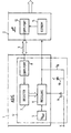
- a block diagram for example, the block diagram showing the essential components of the circuit of a fire detector having at least one sensor for monitoring fire parameters.
- Such detectors are assumed to be known; in this connection, reference is made, for example, to EP-A-0 654 770.
- the block diagram shown shows sections of a customer-specific ASIC Circuit 1 and a microcontroller connected to the ASIC 1 or Microprocessor 2. Between the ASIC 1 and the microprocessor 2 there is a bidirectional Data bus 3.
- the reference symbol K denotes a terminal of the detector, to which a line voltage of, for example, 20 or 30 volts is applied.
- the ASIC 1 contains, among other things, the power management of the circuit, which in particular has a voltage regulator 4. This consists of an integrated in the ASIC 1 Part that a reference voltage source 5, a controller 6, register 7 and a Communication interface 8, and from a part provided outside the ASIC 1 with discrete components, namely an actuator 9 and a backup capacitor 10.
- the actuator 9 is preferably through a junction field effect transistor (JFET) or by a depletion MOSFET and is therefore from the ASIC can be controlled practically without current.
- the microprocessor 2 contains, among other things, a programmable one non-volatile memory 11, for example a PROM, EPROM or EEPROM, and a communication interface 12.
- the voltage regulator 4 regulates the supply voltage from 20 or 30 V to the voltage U g required by the ASIC 1 and the microprocessor 2 with a value of 5 V, this value being matched as precisely as possible.
- the voltage U g passes from the voltage regulator 4 into the ASIC, which passes it on to the microprocessor 2.
- the voltage U g is adjusted in that the voltage regulator 4 is supplied with the required individual adjustment value at a defined point in time, preferably shortly after the start of the circuit, which can take place via the state of a register or the state of several digital signal lines .
- the individual adjustment value is determined by measuring the voltage U g ; this measurement is preferably carried out during the manufacturing process.
- the measured value of U g is compared with the target value U s and an adjustment code is calculated and written on the basis of the difference (U s - U g ).
Landscapes
- Business, Economics & Management (AREA)
- Emergency Management (AREA)
- Physics & Mathematics (AREA)
- General Physics & Mathematics (AREA)
- Fire Alarms (AREA)
- Fire-Detection Mechanisms (AREA)
Description
- zu hoher Strombedarf
- zu hoher Preis
- empfindlich gegenüber äusseren Einflüssen
- teure Kondensatoren erforderlich
- in der Regel nur ein Hersteller.
In der DE-A-33 30 270 ist ein Selbstüberprüfungssystem beschrieben, welches unter anderem einen Spannungsregler enthält, dessen Ausgangsspannung durch in einem Register gespeicherte Werte auf eine maximale und eine minimale Betriebsspannung und auf die Nennbetriebsspannung des zu testenden Systems einstellbar ist. Dieser bekannte Spannungsregler dient zur Bereitstellung verschiedener Spannungswerte im Rahmen des Tests eines mikroprozessorgesteuerten Systems, beispielsweise eines Einchip-Mikrocomputers, und nicht zur Erzeugung einer stabilen Speisespannung für einen im Einsatz stehenden Brandmelder.
Da die Reglereingangsspannung von beispielsweise 20 bis 30V wesentlich höher ist als die Speisespannung von beispielsweise 5V des Mikroprozessors und des ASIC, ist gemäss einer zweiten bevorzugten Ausführungsform ein ASIC-externes Stellglied vorgesehen. Dieses externe Stellglied ist gemäss einer dritten bevorzugten Ausführungsform durch einen direkt vom ASIC ansteuerbaren J-FET gebildet.
Besonders vorteilhaft ist das erfindungsgemässe Konzept dann, wenn der Mikroprozessor einen EEPROM-Speicher und eine bidirektionale Kommunikation zum ASIC aufweist. Denn dann können die Ressourcen optimal genutzt werden: Der Spannungsregler wird im Laufe der Brandmelder-Fertigung abgeglichen und das entsprechende Bitmuster wird in das EEPROM des Mikroprozessors geschrieben. Dieses Bitmuster wird dann beim Einschalten des Brandmelders in das für den Abgleich des Spannungsreglers vorgesehene Register des ASIC geschrieben.
Im folgenden wird der für das Verständnis der Erfindung wesentliche Teil der Schaltung eines erfindungsgemässen Brandmelders anhand eines Blockschemas beispielsweise näher erläutert, wobei das Blockschema die wesentlichen Komponenten der Schaltung eines mindestens einen Sensor zur Überwachung von Brandkenngrössen aufweisenden Brandmelders zeigt. Derartige Melder werden als bekannt vorausgesetzt; es wird in diesem Zusammenhang beispielsweise auf die EP-A-0 654 770 verwiesen.
Claims (9)
- Brandmelder mit einem Sensor zur Überwachung von Brandkenngrössen, mit einem Mikroprozessor und mit einem abgleichbaren Spannungsregler, dadurch gekennzeichnet, dass der Spannungsregler (4) so ausgebildet ist, dass seine Ausgangsspannung (Ug) durch einen in einem Register (11) gespeicherten Abgleichwert abgleichbar ist.
- Brandmelder nach Anspruch 1, dadurch gekennzeichnet, dass der Spannungsregler (4) teilweise in eine nachfolgend als ASIC bezeichnete kundenspezifische Schaltung (1) integriert ist.
- Brandmelder nach Anspruch 2, dadurch gekennzeichnet, dass ein ASIC-externes Stellglied (9) vorgesehen ist.
- Brandmelder nach Anspruch 3, dadurch gekennzeichnet, dass das externe Stellglied (9) durch einen direkt vom ASIC (1) ansteuerbaren Sperrschicht-Feldeffekttransistor (J-FET) gebildet ist.
- Brandmelder nach einem der Ansprüche 1 bis 4, dadurch gekennzeichnet, dass der Abgleichwert in einem nicht-flüchtigen Speicher (11) des Mikroprozessors (2) gespeichert ist.
- Brandmelder nach einem der Ansprüche 2 bis 4, dadurch gekennzeichnet, dass der Abgleichwert in einem nicht-flüchtigen Speicher des ASIC (1) gespeichert ist.
- Brandmelder nach den Ansprüchen 2 und 5, dadurch gekennzeichnet, dass der ASIC (1) ein Abgleichregister (7) und eine Kommunikationsschnittstelle (8) aufweist, und dass zum Abgleich des Spannungsreglers (4) der Abgleichwert in das Abgleichregister überschrieben wird.
- Brandmelder nach einem der Ansprüche 1 bis 7, dadurch gekennzeichnet, dass die Ermittlung des Abgleichwerts während des Fertigungsprozesses des betreffenden Melders erfolgt, wobei die Ausgangsspannung (Ug) gemessen und mit einem Sollwert verglichen und anhand der Abweichung vom Sollwert ein den Abgleichwert repräsentierender Abgleichcode berechnet wird.
- Brandmelder nach Anspruch 8, dadurch gekennzeichnet, dass der Abgleichcode in einem iterativen Verfahren bestimmt wird.
Priority Applications (5)
| Application Number | Priority Date | Filing Date | Title |
|---|---|---|---|
| DE59509782T DE59509782D1 (de) | 1995-08-23 | 1995-08-23 | Brandmelder |
| EP95113206A EP0759602B1 (de) | 1995-08-23 | 1995-08-23 | Brandmelder |
| AT95113206T ATE208074T1 (de) | 1995-08-23 | 1995-08-23 | Brandmelder |
| AU60604/96A AU6060496A (en) | 1995-08-23 | 1996-07-22 | Fire alarm |
| CN96111490A CN1114893C (zh) | 1995-08-23 | 1996-08-23 | 火灾报警器 |
Applications Claiming Priority (1)
| Application Number | Priority Date | Filing Date | Title |
|---|---|---|---|
| EP95113206A EP0759602B1 (de) | 1995-08-23 | 1995-08-23 | Brandmelder |
Publications (2)
| Publication Number | Publication Date |
|---|---|
| EP0759602A1 EP0759602A1 (de) | 1997-02-26 |
| EP0759602B1 true EP0759602B1 (de) | 2001-10-31 |
Family
ID=8219548
Family Applications (1)
| Application Number | Title | Priority Date | Filing Date |
|---|---|---|---|
| EP95113206A Expired - Lifetime EP0759602B1 (de) | 1995-08-23 | 1995-08-23 | Brandmelder |
Country Status (5)
| Country | Link |
|---|---|
| EP (1) | EP0759602B1 (de) |
| CN (1) | CN1114893C (de) |
| AT (1) | ATE208074T1 (de) |
| AU (1) | AU6060496A (de) |
| DE (1) | DE59509782D1 (de) |
Cited By (1)
| Publication number | Priority date | Publication date | Assignee | Title |
|---|---|---|---|---|
| WO2022026408A1 (en) * | 2020-07-28 | 2022-02-03 | Medtronic Mini Med, Inc. | Linear voltage regulator with isolated supply current |
Families Citing this family (2)
| Publication number | Priority date | Publication date | Assignee | Title |
|---|---|---|---|---|
| CN100454347C (zh) * | 2005-12-31 | 2009-01-21 | 首安工业消防有限公司 | 线型火灾探测器数据融合报警系统及方法 |
| CN101810814B (zh) * | 2010-04-28 | 2011-08-10 | 史建钢 | 治疗脑瘫、多动症和痴呆的药物及其制备方法 |
Family Cites Families (4)
| Publication number | Priority date | Publication date | Assignee | Title |
|---|---|---|---|---|
| US4287515A (en) * | 1979-04-27 | 1981-09-01 | Baker Industries, Inc. | Fire detection system with multiple output signals |
| GB2125973A (en) * | 1982-08-23 | 1984-03-14 | Tektronix Inc | Self-test method and apparatus |
| CN2081114U (zh) * | 1990-12-28 | 1991-07-17 | 魏天赐 | 多功能家用防盗防火报警器 |
| CH686913A5 (de) | 1993-11-22 | 1996-07-31 | Cerberus Ag | Anordnung zur Frueherkennung von Braenden. |
-
1995
- 1995-08-23 EP EP95113206A patent/EP0759602B1/de not_active Expired - Lifetime
- 1995-08-23 AT AT95113206T patent/ATE208074T1/de not_active IP Right Cessation
- 1995-08-23 DE DE59509782T patent/DE59509782D1/de not_active Expired - Fee Related
-
1996
- 1996-07-22 AU AU60604/96A patent/AU6060496A/en not_active Abandoned
- 1996-08-23 CN CN96111490A patent/CN1114893C/zh not_active Expired - Fee Related
Cited By (3)
| Publication number | Priority date | Publication date | Assignee | Title |
|---|---|---|---|---|
| WO2022026408A1 (en) * | 2020-07-28 | 2022-02-03 | Medtronic Mini Med, Inc. | Linear voltage regulator with isolated supply current |
| US11960311B2 (en) | 2020-07-28 | 2024-04-16 | Medtronic Minimed, Inc. | Linear voltage regulator with isolated supply current |
| US12405624B2 (en) | 2020-07-28 | 2025-09-02 | Medtronic Minimed, Inc. | Linear voltage regulator and test system |
Also Published As
| Publication number | Publication date |
|---|---|
| CN1114893C (zh) | 2003-07-16 |
| EP0759602A1 (de) | 1997-02-26 |
| CN1149145A (zh) | 1997-05-07 |
| DE59509782D1 (de) | 2001-12-06 |
| AU6060496A (en) | 1997-02-27 |
| ATE208074T1 (de) | 2001-11-15 |
Similar Documents
| Publication | Publication Date | Title |
|---|---|---|
| DE3226179C2 (de) | Schaltungsanordnung zur Überwachung des Ausgangsstroms und der Ausgangsspannung mindestens eines geregelten Netzgerätes | |
| DE10196182B4 (de) | Prozesssteuergeber mit einem extern zugänglichen gemeinsamen Schaltungsnullpunkt und Verfahren zur Herstellung eines Prozesssteuergebers | |
| DE3743846C2 (de) | ||
| EP0690290A1 (de) | Sensor mit einer programmierbaren Schaltwelle | |
| WO2005064424A2 (de) | Prozessmessgerät mit erweiterter hardwarefehlererkennung | |
| DE4338462B4 (de) | Kontrollsystem für elektrische Verbraucher in Kraftfahrzeugen | |
| EP2220460A2 (de) | Feldgerät zur prozessinstrumentierung | |
| DE60016984T2 (de) | Ausfallsicheres Überwachungssystem für ein Potentiometer | |
| WO2003091818A1 (de) | Schaltungsanordnung zur spannungsregelung mittels eines spannungsteilers | |
| DE3249787C2 (de) | ||
| DE3151628A1 (de) | Schaltanordnung zur auswertung analoger messwerte, insbesondere fuer kraftfahrzeuge | |
| EP1966876A1 (de) | Schaltungsanordnung zur versorgung eines feldgerätes der automatisierungstechnik | |
| EP1203933B1 (de) | Sensoranordnung zur Erfassung wenigstens eines Messwerts | |
| DE3008450A1 (de) | Sequentielles uebertragungssystem zum adressenlosen anschliessen mehrerer teilnehmer an eine zentrale | |
| DE10064859A1 (de) | Sensor mit Hilfssensor zur Selbstkalibrierung | |
| EP0759602A1 (de) | Brandmelder | |
| WO2006040203A1 (de) | Sensorschnittstelle mit integrierter strommessung | |
| EP4139753A1 (de) | Feldgerät der automatisierungstechnik | |
| EP0725995B1 (de) | Fernspeiseeinrichtung | |
| DE4409286C1 (de) | Verfahren zum Erkennen der Ursache eines Reset-Vorgangs eines durch einen Mikroprozessor gesteuerten Systems sowie Schaltung zum Durchführen des Verfahrens | |
| WO1998025114A1 (de) | Verfahren zum betreiben eines widerstandsheizelementes und vorrichtung zum durchführen des verfahrens | |
| EP4453672A1 (de) | Verfahren zur regelung des energieverbrauches eines feldgeräts der automatisierungstechnik | |
| AT402131B (de) | Anordnung zur prüfung und einstellung von rundsteuerempfängern | |
| DE10026491A1 (de) | Lichtsensorsystem | |
| DE68912716T2 (de) | Verfahren und Gerät zur Kalibrierung eines einen Analog-Digital-Wandler enthaltenden Systems. |
Legal Events
| Date | Code | Title | Description |
|---|---|---|---|
| PUAI | Public reference made under article 153(3) epc to a published international application that has entered the european phase |
Free format text: ORIGINAL CODE: 0009012 |
|
| AK | Designated contracting states |
Kind code of ref document: A1 Designated state(s): AT BE CH DE DK ES FR GB IE IT LI NL PT SE |
|
| 17P | Request for examination filed |
Effective date: 19970801 |
|
| RAP1 | Party data changed (applicant data changed or rights of an application transferred) |
Owner name: SIEMENS BUILDING TECHNOLOGIES AG |
|
| 17Q | First examination report despatched |
Effective date: 20000621 |
|
| RAP1 | Party data changed (applicant data changed or rights of an application transferred) |
Owner name: SIEMENS BUILDING TECHNOLOGIES AG |
|
| GRAG | Despatch of communication of intention to grant |
Free format text: ORIGINAL CODE: EPIDOS AGRA |
|
| GRAG | Despatch of communication of intention to grant |
Free format text: ORIGINAL CODE: EPIDOS AGRA |
|
| GRAH | Despatch of communication of intention to grant a patent |
Free format text: ORIGINAL CODE: EPIDOS IGRA |
|
| GRAH | Despatch of communication of intention to grant a patent |
Free format text: ORIGINAL CODE: EPIDOS IGRA |
|
| GRAA | (expected) grant |
Free format text: ORIGINAL CODE: 0009210 |
|
| AK | Designated contracting states |
Kind code of ref document: B1 Designated state(s): AT BE CH DE DK ES FR GB IE IT LI NL PT SE |
|
| PG25 | Lapsed in a contracting state [announced via postgrant information from national office to epo] |
Ref country code: NL Free format text: LAPSE BECAUSE OF FAILURE TO SUBMIT A TRANSLATION OF THE DESCRIPTION OR TO PAY THE FEE WITHIN THE PRESCRIBED TIME-LIMIT Effective date: 20011031 Ref country code: IT Free format text: LAPSE BECAUSE OF FAILURE TO SUBMIT A TRANSLATION OF THE DESCRIPTION OR TO PAY THE FEE WITHIN THE PRE;WARNING: LAPSES OF ITALIAN PATENTS WITH EFFECTIVE DATE BEFORE 2007 MAY HAVE OCCURRED AT ANY TIME BEFORE 2007. THE CORRECT EFFECTIVE DATE MAY BE DIFFERENT FROM THE ONE RECORDED.SCRIBED TIME-LIMIT Effective date: 20011031 Ref country code: IE Free format text: LAPSE BECAUSE OF FAILURE TO SUBMIT A TRANSLATION OF THE DESCRIPTION OR TO PAY THE FEE WITHIN THE PRESCRIBED TIME-LIMIT Effective date: 20011031 |
|
| REF | Corresponds to: |
Ref document number: 208074 Country of ref document: AT Date of ref document: 20011115 Kind code of ref document: T |
|
| REG | Reference to a national code |
Ref country code: CH Ref legal event code: EP |
|
| REF | Corresponds to: |
Ref document number: 59509782 Country of ref document: DE Date of ref document: 20011206 |
|
| REG | Reference to a national code |
Ref country code: IE Ref legal event code: FG4D Free format text: GERMAN |
|
| REG | Reference to a national code |
Ref country code: GB Ref legal event code: IF02 |
|
| GBT | Gb: translation of ep patent filed (gb section 77(6)(a)/1977) |
Effective date: 20020106 |
|
| PG25 | Lapsed in a contracting state [announced via postgrant information from national office to epo] |
Ref country code: SE Free format text: LAPSE BECAUSE OF FAILURE TO SUBMIT A TRANSLATION OF THE DESCRIPTION OR TO PAY THE FEE WITHIN THE PRESCRIBED TIME-LIMIT Effective date: 20020131 Ref country code: PT Free format text: LAPSE BECAUSE OF FAILURE TO SUBMIT A TRANSLATION OF THE DESCRIPTION OR TO PAY THE FEE WITHIN THE PRESCRIBED TIME-LIMIT Effective date: 20020131 Ref country code: DK Free format text: LAPSE BECAUSE OF FAILURE TO SUBMIT A TRANSLATION OF THE DESCRIPTION OR TO PAY THE FEE WITHIN THE PRESCRIBED TIME-LIMIT Effective date: 20020131 |
|
| NLV1 | Nl: lapsed or annulled due to failure to fulfill the requirements of art. 29p and 29m of the patents act | ||
| PG25 | Lapsed in a contracting state [announced via postgrant information from national office to epo] |
Ref country code: ES Free format text: LAPSE BECAUSE OF FAILURE TO SUBMIT A TRANSLATION OF THE DESCRIPTION OR TO PAY THE FEE WITHIN THE PRESCRIBED TIME-LIMIT Effective date: 20020430 |
|
| REG | Reference to a national code |
Ref country code: IE Ref legal event code: FD4D |
|
| PG25 | Lapsed in a contracting state [announced via postgrant information from national office to epo] |
Ref country code: AT Free format text: LAPSE BECAUSE OF NON-PAYMENT OF DUE FEES Effective date: 20020823 |
|
| PLBE | No opposition filed within time limit |
Free format text: ORIGINAL CODE: 0009261 |
|
| STAA | Information on the status of an ep patent application or granted ep patent |
Free format text: STATUS: NO OPPOSITION FILED WITHIN TIME LIMIT |
|
| 26N | No opposition filed | ||
| REG | Reference to a national code |
Ref country code: CH Ref legal event code: PFA Owner name: SIEMENS BUILDING TECHNOLOGIES AG C-IPR Free format text: SIEMENS BUILDING TECHNOLOGIES AG#BELLERIVESTRASSE 36#8034 ZUERICH (CH) -TRANSFER TO- SIEMENS BUILDING TECHNOLOGIES AG C-IPR#GUBELSTRASSE 22#6300 ZUG (CH) |
|
| PGFP | Annual fee paid to national office [announced via postgrant information from national office to epo] |
Ref country code: DE Payment date: 20071022 Year of fee payment: 13 |
|
| PGFP | Annual fee paid to national office [announced via postgrant information from national office to epo] |
Ref country code: CH Payment date: 20071112 Year of fee payment: 13 |
|
| REG | Reference to a national code |
Ref country code: FR Ref legal event code: TP Ref country code: FR Ref legal event code: CD |
|
| PGFP | Annual fee paid to national office [announced via postgrant information from national office to epo] |
Ref country code: FR Payment date: 20080822 Year of fee payment: 14 |
|
| PGFP | Annual fee paid to national office [announced via postgrant information from national office to epo] |
Ref country code: GB Payment date: 20080811 Year of fee payment: 14 |
|
| REG | Reference to a national code |
Ref country code: CH Ref legal event code: PUE Owner name: SIEMENS AKTIENGESELLSCHAFT Free format text: SIEMENS BUILDING TECHNOLOGIES AG C-IPR#GUBELSTRASSE 22#6300 ZUG (CH) -TRANSFER TO- SIEMENS AKTIENGESELLSCHAFT#WITTELSBACHERPLATZ 2#80333 MUENCHEN (DE) Ref country code: CH Ref legal event code: NV Representative=s name: SIEMENS SCHWEIZ AG |
|
| PGFP | Annual fee paid to national office [announced via postgrant information from national office to epo] |
Ref country code: BE Payment date: 20080820 Year of fee payment: 14 |
|
| REG | Reference to a national code |
Ref country code: CH Ref legal event code: PL |
|
| REG | Reference to a national code |
Ref country code: GB Ref legal event code: 732E Free format text: REGISTERED BETWEEN 20090514 AND 20090520 |
|
| PG25 | Lapsed in a contracting state [announced via postgrant information from national office to epo] |
Ref country code: LI Free format text: LAPSE BECAUSE OF NON-PAYMENT OF DUE FEES Effective date: 20080831 Ref country code: CH Free format text: LAPSE BECAUSE OF NON-PAYMENT OF DUE FEES Effective date: 20080831 |
|
| PG25 | Lapsed in a contracting state [announced via postgrant information from national office to epo] |
Ref country code: DE Free format text: LAPSE BECAUSE OF NON-PAYMENT OF DUE FEES Effective date: 20090303 |
|
| BERE | Be: lapsed |
Owner name: *SIEMENS BUILDING TECHNOLOGIES A.G. Effective date: 20090831 |
|
| GBPC | Gb: european patent ceased through non-payment of renewal fee |
Effective date: 20090823 |
|
| REG | Reference to a national code |
Ref country code: FR Ref legal event code: ST Effective date: 20100430 |
|
| PG25 | Lapsed in a contracting state [announced via postgrant information from national office to epo] |
Ref country code: BE Free format text: LAPSE BECAUSE OF NON-PAYMENT OF DUE FEES Effective date: 20090831 |
|
| PG25 | Lapsed in a contracting state [announced via postgrant information from national office to epo] |
Ref country code: FR Free format text: LAPSE BECAUSE OF NON-PAYMENT OF DUE FEES Effective date: 20090831 |
|
| PG25 | Lapsed in a contracting state [announced via postgrant information from national office to epo] |
Ref country code: GB Free format text: LAPSE BECAUSE OF NON-PAYMENT OF DUE FEES Effective date: 20090823 |