EP0759524B1 - Pipe with external insulation for feeding a molten substance at high temperature - Google Patents
Pipe with external insulation for feeding a molten substance at high temperature Download PDFInfo
- Publication number
- EP0759524B1 EP0759524B1 EP96113409A EP96113409A EP0759524B1 EP 0759524 B1 EP0759524 B1 EP 0759524B1 EP 96113409 A EP96113409 A EP 96113409A EP 96113409 A EP96113409 A EP 96113409A EP 0759524 B1 EP0759524 B1 EP 0759524B1
- Authority
- EP
- European Patent Office
- Prior art keywords
- pipe
- thermal insulation
- insulation material
- pipes
- noble metal
- Prior art date
- Legal status (The legal status is an assumption and is not a legal conclusion. Google has not performed a legal analysis and makes no representation as to the accuracy of the status listed.)
- Expired - Lifetime
Links
Images


Classifications
-
- F—MECHANICAL ENGINEERING; LIGHTING; HEATING; WEAPONS; BLASTING
- F16—ENGINEERING ELEMENTS AND UNITS; GENERAL MEASURES FOR PRODUCING AND MAINTAINING EFFECTIVE FUNCTIONING OF MACHINES OR INSTALLATIONS; THERMAL INSULATION IN GENERAL
- F16L—PIPES; JOINTS OR FITTINGS FOR PIPES; SUPPORTS FOR PIPES, CABLES OR PROTECTIVE TUBING; MEANS FOR THERMAL INSULATION IN GENERAL
- F16L59/00—Thermal insulation in general
- F16L59/14—Arrangements for the insulation of pipes or pipe systems
- F16L59/16—Arrangements specially adapted to local requirements at flanges, junctions, valves or the like
-
- C—CHEMISTRY; METALLURGY
- C03—GLASS; MINERAL OR SLAG WOOL
- C03B—MANUFACTURE, SHAPING, OR SUPPLEMENTARY PROCESSES
- C03B5/00—Melting in furnaces; Furnaces so far as specially adapted for glass manufacture
- C03B5/16—Special features of the melting process; Auxiliary means specially adapted for glass-melting furnaces
- C03B5/225—Refining
- C03B5/2252—Refining under reduced pressure, e.g. with vacuum refiners
-
- F—MECHANICAL ENGINEERING; LIGHTING; HEATING; WEAPONS; BLASTING
- F16—ENGINEERING ELEMENTS AND UNITS; GENERAL MEASURES FOR PRODUCING AND MAINTAINING EFFECTIVE FUNCTIONING OF MACHINES OR INSTALLATIONS; THERMAL INSULATION IN GENERAL
- F16L—PIPES; JOINTS OR FITTINGS FOR PIPES; SUPPORTS FOR PIPES, CABLES OR PROTECTIVE TUBING; MEANS FOR THERMAL INSULATION IN GENERAL
- F16L59/00—Thermal insulation in general
- F16L59/14—Arrangements for the insulation of pipes or pipe systems
-
- F—MECHANICAL ENGINEERING; LIGHTING; HEATING; WEAPONS; BLASTING
- F27—FURNACES; KILNS; OVENS; RETORTS
- F27D—DETAILS OR ACCESSORIES OF FURNACES, KILNS, OVENS OR RETORTS, IN SO FAR AS THEY ARE OF KINDS OCCURRING IN MORE THAN ONE KIND OF FURNACE
- F27D1/00—Casings; Linings; Walls; Roofs
- F27D1/04—Casings; Linings; Walls; Roofs characterised by the form, e.g. shape of the bricks or blocks used
- F27D1/045—Bricks for lining cylindrical bodies, e.g. skids, tubes
-
- F—MECHANICAL ENGINEERING; LIGHTING; HEATING; WEAPONS; BLASTING
- F27—FURNACES; KILNS; OVENS; RETORTS
- F27D—DETAILS OR ACCESSORIES OF FURNACES, KILNS, OVENS OR RETORTS, IN SO FAR AS THEY ARE OF KINDS OCCURRING IN MORE THAN ONE KIND OF FURNACE
- F27D3/00—Charging; Discharging; Manipulation of charge
- F27D3/14—Charging or discharging liquid or molten material
Definitions
- the present invention relates to a backup structure or device for feeding a molten substance of high temperature used for a vacuum degassing apparatus for removing air bubbles in a molten material of high temperature in a process wherein a molten material of high temperature such as molten glass, molten metal or the like is continuously supplied.
- a vacuum degassing apparatus is employed in a process wherein molten glass G as a molten substance of high temperature in a melting tank 1 is degassed and is continuously fed to a successive treating furnace.
- the vacuum degassing apparatus has a vacuum housing 2 in which air is sucked in vacuum and a vacuum degassing vessel 3 which is accommodated in the vacuum housing 2.
- the vacuum degassing vessel 3 is communicated with an uprising pipe 4 through which the molten glass G as a molten substance of high temperature is introduced upwardly and then, subjecting to a degassing treatment.
- the vacuum degassing vessel is communicated with a downfalling pipe 5 through which the molten glass G after having subjected to the degassing treatment is introduced downwardly to the successive treating furnace.
- Housings 6 and 7 are provided around the uprising pipe 4 and the downfalling pipe 5, respectively, so as to insulatively surround the uprising pipe 4 and the downfalling pipe 5.
- the molten glass G is introduced to the vacuum degassing vessel 3 by a "siphon" effect, where the molten glass G is degassed.
- Such vacuum degassing vessel employing the "siphon" effect is described in U.S.P. 3519412, U.S.P. 5316563 and Japanese Unexamined Patent Publication Nos. 221129/1990, 33020/1991, 69516/1991, 31325/1992, 58646/1993, 208830/1993, 208845/1993, 229831/1993 and 305735/1994.
- the uprising pipe 4 and the downfalling pipe 5 are made of a noble metal such as platinum since temperature of these pipes are elevated up to 1,200 to 1,400°C by the molten glass G.
- a pressure inside the vacuum degassing vessel 3 is reduced to 1/20 to 1/3 atmospheric pressure. Accordingly, it is necessary to set a difference of levels of the molten glass G in the melting tank 1 and the molten glass G in the vacuum degassing vessel 3, in accordance with a degree of vacuum in the vacuum degassing vessel 3. Accordingly, a determined difference of the levels may prolong the lengths of the uprising pipe 4 and the downfalling pipe 5 whereby the thermal expansion quantities of the uprising pipe 4 and the downfalling pipe 5 are increased.
- Thermal insulation materials 6A, 7A are disposed in the housings 6, 7 respectively.
- the thermal insulation materials 6A, 7A also have a certain thermal expansion coefficient.
- the thermal expansion coefficient of the thermal insulation materials 6A, 7A is different from that of the uprising pipe 4 or the downfalling pipe 5, there produces a difference of thermal expansion quantities between the thermal insulation materials 6A, 7A and the uprising pipe 4 or the downfalling pipe 5 whereby the structure of the vacuum degassing apparatus becomes unstable to thereby be insufficient in safety.
- JP-A-03 033 020 describes a device comprising the features defining the preamble of claim 1 of the present invention.
- the present invention provides a device for feeding molten glass from a melting tank through a vacuum degassing vessel to a downstream molten glass pool, which comprises an uprising and a downfalling pipe of noble metal each having an upper end connected to the vessel and a lower end immersed in the molten glass in the tank, a thermal insulation material being disposed to surround each of the pipes, and containers each accommodating the thermal insulation material, a plurality of projections being provided on the outer periphery of the pipes at predetermined intervals, and each being held at its both sides by the thermal insulation material.
- one embodiment of the present invention is to provide the above-mentioned backup structure wherein the pipe for feeding a molten substance of high temperature comprises a plurality of segmentary pipes arranged on the same axial line, and each of the segmentary pipes has a pair of flanges at its both ends so that each flange constitutes an element of each of the projections.
- each of the projections comprises two overlaid flanges.
- one embodiment of the present invention is to provide the above-mentioned device wherein a gap is formed between the pipe for feeding a molten substance of high temperature and the thermal insulation material so as to absorb a deformation of flexure of the pipe, and each of the projections is held at its both sides by the thermal insulation material so as to minimize the deformation.
- a thermal insulation material having a thermal expansion coefficient which is different from that of a pipe for feeding a molten material of high temperature is disposed around the pipe, a plurality of projections are formed outwardly from the pipe, and each of the projections is held at its both sides by the thermal insulation material.
- each of the projections is fixed by the thermal insulation material. Accordingly, quantities of deformation of the pipes, which are caused by bending stresses in the pipes thermally expanded, are dispersed uniformly between adjacent projections of the pipes. Accordingly, the quantities of deformation of the pipes can be minimized.
- the pipes for feeding a molten substance of high temperature comprise a plurality of segmentary pipes which are arranged on the same axial line; each of the segmentary pipes has a pair of flanges as projections at its both ends and the thermal insulation material is clamped by the flanges. Accordingly, even when a segmentary pipe is deformed by a thermal bending force, the bending force is not transmitted to the adjacent segmentary pipes, whereby a quantity of deformation by bending in the pipe can further be minimized.
- a gap is formed between the outer periphery of the pipe and the thermal insulation material. Accordingly, a thermal expansion in the outer peripheral direction in the pipe when thermally expanded, is absorbed by the gap, whereby a deformation of the thermally expanded pipe due to forcible contact of it to the thermal insulation material, is avoidable.
- the length of the supporting device in the direction along the pipe is made partially changeable between a time period that the pipe is in an elevated temperature and a time period that the pipe is not in an elevated temperature.
- the length of the supporting device in the direction along the pipe at the time of an evaluated temperature is elongated. Accordingly, thermal expansion quantity in the pipe can be absorbed.
- the supporting device further comprises a container for supporting the thermal insulation material wherein a part of the container has contraction and expansion properties. Accordingly, when the supporting device is in an elevated temperature, the part of the container is expanded whereby a thermal expansion quantity in the pipe can be absorbed.
- a supporting device for supporting a thermal insulation material for surrounding the circumference of a pipe for feeding a molten substance of high temperature which comprises;
- thermal expansion quantity of the pipe and the thermal insulation material can be released downwardly against an urging force of the push-up means whereby the thermal expansion quantity of the pipe can be absorbed.
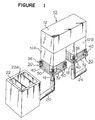
- Figure 1 is a perspective view showing a vacuum degassing apparatus in which the backup structure for a pipe for feeding a molten substance of high temperature of the present invention is used
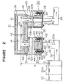
- Figure 2 is a longitudinal cross-sectional view of the vacuum degassing apparatus.
- a vacuum degassing apparatus 10 includes a vacuum housing 12 which is generally in a gate-like form, i.e. an inverted U-Form. As shown in Figure 2, a vacuum degassing vessel 14 is disposed in an upper portion of the vacuum housing 12. An uprising pipe 16 (a pipe for feeding a molten substance of high temperature) made of platinum is connected to the vacuum degassing vessel 14 at a left end portion in the drawings, and a downfalling pipe 18 (a pipe for feeding a molten substance of high temperature) made of platinum is connected to the vacuum degassing vessel 14 at a right end portion in the drawings. The uprising pipe 16 and the downfalling pipe 18 are respectively disposed in leg portions 12A, 12B of the vacuum housing 12.
- the lower end portion of the uprising pipe 16 is fitted to an open end of an upstream guiding duct 20 and is immersed in a molten glass G in the upstream guiding duct 20 which is communicated with melting tank 22.
- the lower end portion of the downfalling pipe 18 is fitted to an open end of a downstream guiding duct 24 and is immersed in the molten glass G in the downstream guiding duct 24.
- Bricks 26 for heat insulation are disposed around the vacuum degassing vessel 14 so as to cover it.
- Bricks (thermal insulation materials) 28 for heat insulation are disposed so as to surround the uprising pipe 16 and the downfalling pipe 18 respectively so that the bricks 28 support the uprising pipe 16 and the downfalling pipe 18 respectively.
- a condition of reduced pressure in the vacuum degassing vessel 14 is set to be 1/20 to 1/3 atmospheric pressure.
- the difference H between the levels of the molten glass G in the melting tank 22 and the molten glass G in the vacuum degassing vessel 14, is determined to be a difference of level to which the "siphon" principle is applied. Namely, when a pressure in the vacuum degassing vessel 14 is set to be 1/20 to 1/3 atmospheric pressure, a difference of level of about several meters is needed between the levels of the molten glass G in the melting tank 22 and the molten glass G in the vacuum degassing vessel 14 in order to apply the "siphon" principle to the vacuum degassing apparatus 10.
- the vacuum degassing apparatus 10 comprises a pair of supporting devices 30 which support respectively pipes for feeding a molten substance of high temperature.
- the supporting devices 30 support respectively backup structures 31 (including the uprising pipe 16, the downfalling pipe 18 and the bricks 28 for heat insulation). Since the construction of the supporting device 30 and the backup structure 31 which support the uprising pipe is the same as the construction of the supporting device 30 and the backup structure 31 which support the downfalling pipe, description will be made only to the supporting device 30 and the backup structure 31 for the uprising pipe, and description on the supporting device 30 and the backup structure 31 for the downfalling pipe will be omitted.
- the supporting device 30 for the uprising pipe 16 comprises a supporting plate 32 and a push-up means 36. As shown in Figures 2 and 3, the bricks 28 are placed on the supporting plate 32, and the bricks 28 are arranged around the uprising pipe 16 so as to surround it.
- the leg portion 12A of the vacuum housing 12 is formed to be a rectangular prism-like cylindrical form, and supporting members 40, 40... are fixed at four corners of the leg portion 12A of rectangular prism-like cylindrical form ( Figure 1).
- the push-up means 36 connects the leg portion 12A to the supporting plate 32 and urges the supporting plate 32 upwardly.
- the supporting members 40, 40... accommodating push-up means 36 are arranged at the four corners of the supporting plate 32 having a rectangular shape.
- a bolt 42 in each of the push-up means 36 is fitted to an opening formed in the lower end portion of each of the supporting members 40 and each opening formed in the supporting plate 32 (the both opening are not shown in the Figures).
- Nuts 44, 44 are screwed to the upper and lower ends of the bolt 42 respectively, and a coil spring 46 is disposed between the lower end portion of the supporting member 40 and the nut 44 at the upper end portion of the bolt 42 in a compressed state. Accordingly, the urging force of the coil spring pushes the bolt 42 upwardly, and the supporting plate 32 is pushed upwardly by means of the bolt 42.
- a cylindrical bellows 50 is disposed to connect between the leg portion 12A of the vacuum housing 12 and the supporting plate 32 and to accommodate the bricks 28 therein whereby the inside of the vacuum housing 12 can be kept to be in an airtight condition. Accordingly, air in the vacuum housing 12 can be sucked by a vacuum pump (not shown).
- the backup structure 31 for a pipe for feeding a molten substance of high temperature is provided with flanges of annular shape (annular projections) 16A, 16A ... at the outer circumference of the uprising pipe 16 with certain intervals h in the vertical direction.
- the bricks 28A... for heat insulation used for the backup structure are stacked at the outer circumferential side of the uprising pipe 16 go that each of the flanges 16A is interposed between upper and lower bricks 28A, 28A which are in contact in their substantial portions.
- a recess 28A1 is formed at an upper surface of each of the bricks 28A, and the depth of the recess 28A1 is substantially the same as the thickness of each of the flanges 16A.
- the elongation of a part of uprising pipe 16 which is between vertically adjacent flanges 16A, 16A is larger than that of the brick 28A arranged between adjacent flanges 16A, 16A. Accordingly, the elongation in the axial direction of the part of uprising pipe 16 is restricted by the bricks 28A whereby the part of uprising pipe is deformed inwardly in a curved form or a sinuous form as shown in Figure 5.
- the elongation in the axial direction of the uprising pipe as a whole corresponds to the elongation of the stacked bricks 28A.
- the bricks 28A are electro-galvanized bricks of zirconia type, for instance, and have corrosion resistance to the molten glass G. Accordingly, even when the molten glass G leaks outside the uprising pipe 16 due to a crack in the uprising pipe 16, leaking of the molten glass G can be suppressed by the bricks 28A... having corrosion resistance.
- the space s can accommodate an amount of expansion of the uprising pipe 16 when it is expanded outwardly due to its thermal expansion. Accordingly, deformation of the uprising pipe 16 caused by the contact of it to the bricks 28A... at the time of the thermal expansion can be prevented.
- An urging force of each of the coil springs 46, 46... is adjusted by turning each of the nuts 44, 44... screwed to the upper end portion of each of the bolts 42, 42... which are elements for constituting the supporting device 30 of the present invention, so that a pressing force wherein the bricks 28 placed on the supporting plate 32 push the pressing plate 48, is brought to a predetermined value. Then, the vacuum pump (not shown) is operated to suck air in the vacuum housing 12 and the vacuum degassing vessel 14 in a vacuumed condition.
- the uprising pipe 16 and other structural elements are heated to be at a constant temperature by supplying an electric current.
- the molten glass G in the melting tank ascends in the uprising pipe 16 to be introduced to the vacuum degassing vessel 14 in which the molten glass G is degassed under a reduced pressure condition.
- the molten glass G which has undergone degassing is introduced to the downstream guiding duct 24 through the downfalling pipe 18.
- the uprising pipe 16, the downfalling pipe 18 and the bricks 28 are expanded by heat. Since the flanges 16A are held at their both sides by upper and lower bricks 28A, 28A, the elongation in the axial direction of the uprising pipe 16 is restricted by bricks 28A whereby it is bent inwardly with respect to the outer circumference of the uprising pipe 16 as shown in Figure 5. Accordingly, the elongation in the axial direction of the uprising pipe 16 itself corresponds to the elongation of the stacked bricks 28A as a whole.
- a difference of thermal expansion between the uprising pipe 16 and the stacked bricks 28A is dispersed in the portions of the uprising pipe 16 which correspond to the distance between vertically adjacent flanges 16A, 16A.
- the deformation quantities of the uprising pipe 16 are dispersed uniformly in the portions between adjacent flanges 16A, 16A whereby the deformation quantity of the uprising pipe 16 in its entirety can be minimized.
- the bricks 28A... have corrosion resistance to the molten glass G. Accordingly, even when a crack or the like takes place in the uprising pipe 16 and the molten glass G leaks outside the uprising pipe 16, there is no leakage of the molten glass G since the bricks 28A... are not corroded.
- the bricks 28A... are arranged with a predetermined space s with respect to the outer circumference of the uprising pipe 16, the space s absorbs the expansion of the uprising pipe 16 in the outer circumferential direction when it is expanded by heat. Accordingly, the forcible contact of the uprising pipe 16 to the bricks 28A... at the time of the thermal expansion can be prevented to thereby avoid the deformation of the uprising pipe 16.
- the upper end portion of the stacked bricks 28A... for restricting the elongation in the axial direction of the uprising pipe 16 is in contact with the pressing plate 48. Accordingly, the uprising pipe 16 and the stacked bricks 28A... elongate downwardly, and the elongation quantities in the axial direction of the uprising pipe 16 and the stacked bricks 26A... are the same.
- an urging force of each of the coil springs 46, 46... should be adjusted by turning each of the nuts 44, 44... screwed to the upper end of each of the bolts 42, 42..., depending on the thermal expansion quantities of the uprising pipe 16, the downfalling pipe 18 and the bricks 28A....
- the flange 16A, 16A... are formed at the outer circumference of the uprising pipe 16 at predetermined intervals.
- the uprising pipe 16 comprises a plurality of segmentary pipes 60 arranged on the same axial line, and a pair of flanges 60A are formed at upper and lower end portions of each of the segmentary pipes 60, may be used.
- two flanges 60A, 60A are overlaid. Accordingly, a recess 28A1 is formed in the upper end portion of the brick 28A, and a recess 28A2 is formed in the lower end portion of the brick 28A.
- the two overlaid flanges 60A, 60A are held by the bricks 28A, 28A stacked vertically in the same manner as the above-mentioned embodiment. Even when a segmentary pipe 60 is deformed by a bending stress, the bending stress is not transmitted to adjacent segmentary pipes 60, 60. Accordingly, a deformation quantity in the pipe can further be minimized.
- the supporting device 30 is expanded in the direction of the pipe depending on the thermal expansion in the downward direction of the bricks 28, there is another embodiment wherein the supporting device comprises a plurality of containers arranged in the direction of the pipe; the plurality of containers are independent in a time period that the pipe is not in an elevated temperature; and the plurality of containers are fixedly connected by means of a caulking material or welding in a time period that the pipe is in an elevated temperature by passing therethrough a molten substance of high temperature.
- a plurality of projections projecting from the pipe are held by a thermal insulation material. Accordingly, a deformation quantity of the pipe at the time of thermal expansion can be dispersed uniformly between adjacent projections. With such structure, a deformation in the pipe can be kept small. Accordingly, a failure such as cracking is prevented from occurring in the pipe to increase safety for the structure.
- the pipe comprises a plurality of segmentary pipes arranged on the same axial line. Even when there takes place a deformation in a segmentary pipe by a bending stress, the bending stress is not transmitted to adjacent segmentary pipes. Accordingly, a deformation by a bending stress in the pipe can further be minimized.
- a gap is formed between the outer circumference of the pipe and the thermal insulation material, a thermal expansion quantity in the outer circumferential direction of the pipe, when thermally expanded, can be released in the gap. Accordingly, a deformation in the pipe by the press-contact of it to the thermal insulation material can be prevented.
- the length of the supporting device along the direction of the pipe is partially changeable between a time period that the pipe is in an elevated temperature by passing therethrough the molten substance of high temperature and a time period that the pipe is not in an elevated temperature, and the length of the supporting device in the direction of the pipe is elongated at the time of high temperature. Accordingly, the thermal expansion quantity of the pipe can be absorbed.
- a supporting plate is fixed to a lower end of the pipe and a thermal insulation material is arranged around the pipe.
- the supporting plate is connected to a housing by means of a push-up means which supports the thermal insulation material by urging upwardly the supporting plate. Accordingly, thermal expansion quantities of the pipe and the thermal insulation material are released downwardly against an urging force of the push-up means. The thermal expansion quantity of the pipe is absorbed, and security in a device using the pipe can be assured.
- the housing and the supporting plate are connected by a cylindrical bellows, and the cylindrical bellows accommodates the thermal insulation material.
- the inside of the housing is maintained in an airtight condition, and the inside of the housing can be brought to a vacuum condition by operating a vacuum pump communicated to the housing.
Landscapes
- Engineering & Computer Science (AREA)
- General Engineering & Computer Science (AREA)
- Mechanical Engineering (AREA)
- Chemical & Material Sciences (AREA)
- Materials Engineering (AREA)
- Organic Chemistry (AREA)
- Treatment Of Steel In Its Molten State (AREA)
- Thermal Insulation (AREA)
- Furnace Housings, Linings, Walls, And Ceilings (AREA)
- Furnace Details (AREA)
Description
- The present invention relates to a backup structure or device for feeding a molten substance of high temperature used for a vacuum degassing apparatus for removing air bubbles in a molten material of high temperature in a process wherein a molten material of high temperature such as molten glass, molten metal or the like is continuously supplied.
- As shown in Figure 7, a vacuum degassing apparatus is employed in a process wherein molten glass G as a molten substance of high temperature in a melting tank 1 is degassed and is continuously fed to a successive treating furnace. Namely, the vacuum degassing apparatus has a vacuum housing 2 in which air is sucked in vacuum and a vacuum degassing vessel 3 which is accommodated in the vacuum housing 2. The vacuum degassing vessel 3 is communicated with an
uprising pipe 4 through which the molten glass G as a molten substance of high temperature is introduced upwardly and then, subjecting to a degassing treatment. The vacuum degassing vessel is communicated with adownfalling pipe 5 through which the molten glass G after having subjected to the degassing treatment is introduced downwardly to the successive treating furnace.Housings uprising pipe 4 and thedownfalling pipe 5, respectively, so as to insulatively surround theuprising pipe 4 and thedownfalling pipe 5. The molten glass G is introduced to the vacuum degassing vessel 3 by a "siphon" effect, where the molten glass G is degassed. Such vacuum degassing vessel employing the "siphon" effect is described in U.S.P. 3519412, U.S.P. 5316563 and Japanese Unexamined Patent Publication Nos. 221129/1990, 33020/1991, 69516/1991, 31325/1992, 58646/1993, 208830/1993, 208845/1993, 229831/1993 and 305735/1994. - The
uprising pipe 4 and thedownfalling pipe 5 are made of a noble metal such as platinum since temperature of these pipes are elevated up to 1,200 to 1,400°C by the molten glass G. - In the vacuum degassing apparatus of this kind, a pressure inside the vacuum degassing vessel 3 is reduced to 1/20 to 1/3 atmospheric pressure. Accordingly, it is necessary to set a difference of levels of the molten glass G in the melting tank 1 and the molten glass G in the vacuum degassing vessel 3, in accordance with a degree of vacuum in the vacuum degassing vessel 3. Accordingly, a determined difference of the levels may prolong the lengths of the
uprising pipe 4 and thedownfalling pipe 5 whereby the thermal expansion quantities of theuprising pipe 4 and thedownfalling pipe 5 are increased. -
Thermal insulation materials housings thermal insulation materials thermal insulation materials uprising pipe 4 or thedownfalling pipe 5, there produces a difference of thermal expansion quantities between thethermal insulation materials uprising pipe 4 or thedownfalling pipe 5 whereby the structure of the vacuum degassing apparatus becomes unstable to thereby be insufficient in safety. - The above-cited JP-A-03 033 020 describes a device comprising the features defining the preamble of claim 1 of the present invention.
- It is the object of the invention to provide a device for feeding molten glass from a melting tank though a vacuum degassing vessel, which absorbs thermal expansion quantities of an uprising pipe and a downfalling pipe so that the safety in the device is improved.
- This object is fulfilled by a device for feeding molten glass having the features disclosed in claim 1. Preferred embodiments are defined in the dependent subclaims.
- To achieve the above-mentioned object, the present invention provides a device for feeding molten glass from a melting tank through a vacuum degassing vessel to a downstream molten glass pool, which comprises an uprising and a downfalling pipe of noble metal each having an upper end connected to the vessel and a lower end immersed in the molten glass in the tank, a thermal insulation material being disposed to surround each of the pipes, and containers each accommodating the thermal insulation material, a plurality of projections being provided on the outer periphery of the pipes at predetermined intervals, and each being held at its both sides by the thermal insulation material.
- In order to achieve the above-mentioned object, one embodiment of the present invention is to provide the above-mentioned backup structure wherein the pipe for feeding a molten substance of high temperature comprises a plurality of segmentary pipes arranged on the same axial line, and each of the segmentary pipes has a pair of flanges at its both ends so that each flange constitutes an element of each of the projections. Preferrably, each of the projections comprises two overlaid flanges.
- In order to achieve the above-mentioned object, one embodiment of the present invention is to provide the above-mentioned device wherein a gap is formed between the pipe for feeding a molten substance of high temperature and the thermal insulation material so as to absorb a deformation of flexure of the pipe, and each of the projections is held at its both sides by the thermal insulation material so as to minimize the deformation.
- In accordance with an aspect of the present invention, a thermal insulation material having a thermal expansion coefficient which is different from that of a pipe for feeding a molten material of high temperature is disposed around the pipe, a plurality of projections are formed outwardly from the pipe, and each of the projections is held at its both sides by the thermal insulation material. With this structure, each of the projections is fixed by the thermal insulation material. Accordingly, quantities of deformation of the pipes, which are caused by bending stresses in the pipes thermally expanded, are dispersed uniformly between adjacent projections of the pipes. Accordingly, the quantities of deformation of the pipes can be minimized.
- In accordance with an aspect of the present invention, the pipes for feeding a molten substance of high temperature comprise a plurality of segmentary pipes which are arranged on the same axial line; each of the segmentary pipes has a pair of flanges as projections at its both ends and the thermal insulation material is clamped by the flanges. Accordingly, even when a segmentary pipe is deformed by a thermal bending force, the bending force is not transmitted to the adjacent segmentary pipes, whereby a quantity of deformation by bending in the pipe can further be minimized.
- In accordance with an aspect of the present invention, a gap is formed between the outer periphery of the pipe and the thermal insulation material. Accordingly, a thermal expansion in the outer peripheral direction in the pipe when thermally expanded, is absorbed by the gap, whereby a deformation of the thermally expanded pipe due to forcible contact of it to the thermal insulation material, is avoidable.
- In accordance with one embodiment of the present invention, the length of the supporting device in the direction along the pipe is made partially changeable between a time period that the pipe is in an elevated temperature and a time period that the pipe is not in an elevated temperature. In particular, the length of the supporting device in the direction along the pipe at the time of an evaluated temperature is elongated. Accordingly, thermal expansion quantity in the pipe can be absorbed.
- In the invention mentioned just above, the supporting device further comprises a container for supporting the thermal insulation material wherein a part of the container has contraction and expansion properties. Accordingly, when the supporting device is in an elevated temperature, the part of the container is expanded whereby a thermal expansion quantity in the pipe can be absorbed.
- In accordance with one embodiment of the present invention, there is provided a supporting device for supporting a thermal insulation material for surrounding the circumference of a pipe for feeding a molten substance of high temperature which comprises;
- a supporting plate fixed to a lower end of the pipe which is suspended from a housing,
- a thermal insulation material arranged around the pipe and placed on the supporting plate, and
- a push-up means which connects the supporting plate to the housing and forces upwardly the supporting plate to support the thermal insulation material, whereby expansion forces of the pipe and the thermal insulation material are released downwardly against an urging force of the push-up means.
-
- With the supporting device mentioned just above, thermal expansion quantity of the pipe and the thermal insulation material can be released downwardly against an urging force of the push-up means whereby the thermal expansion quantity of the pipe can be absorbed.
- In drawings:
- Figure 1 is a perspective view of a vacuum degassing apparatus in which the backup structure for a pipe for feeding a molten substance of high temperature according to the present invention, is used;
- Figure 2 is a diagram partly cross-sectioned showing the vacuum degassing apparatus in which the backup structure according to the present invention is used;
- Figure 3 is an enlarged front view partly cross-sectioned which shows an important portion of the backup structure according to the present invention;
- Figure 4 is an enlarged cross-sectional view showing an embodiment of the backup structure of the present invention in which flanges provided in an uprising pipe are held from their both sides;
- Figure 5 is an enlarged cross-sectional view showing the backup structure of the present invention in which the pipe is in an expanded state;
- Figure 6 is an enlarged cross-sectional view showing another embodiment of the backup structure for pipe for feeding a molten substance of high temperature according to the present invention; and
- Figure 7 is a cross-sectional view of a conventional vacuum degassing apparatus.
-
- Preferred embodiments of the backup structure for a pipe for feeding a molten substance of high temperature of the present invention will be described in detail with reference to the drawings.
- Figure 1 is a perspective view showing a vacuum degassing apparatus in which the backup structure for a pipe for feeding a molten substance of high temperature of the present invention is used, and Figure 2 is a longitudinal cross-sectional view of the vacuum degassing apparatus.
- In Figure 1, a
vacuum degassing apparatus 10 includes avacuum housing 12 which is generally in a gate-like form, i.e. an inverted U-Form. As shown in Figure 2, avacuum degassing vessel 14 is disposed in an upper portion of thevacuum housing 12. An uprising pipe 16 (a pipe for feeding a molten substance of high temperature) made of platinum is connected to thevacuum degassing vessel 14 at a left end portion in the drawings, and a downfalling pipe 18 (a pipe for feeding a molten substance of high temperature) made of platinum is connected to thevacuum degassing vessel 14 at a right end portion in the drawings. Theuprising pipe 16 and the downfallingpipe 18 are respectively disposed inleg portions vacuum housing 12. - The lower end portion of the
uprising pipe 16 is fitted to an open end of an upstream guidingduct 20 and is immersed in a molten glass G in the upstream guidingduct 20 which is communicated withmelting tank 22. The lower end portion of the downfallingpipe 18 is fitted to an open end of a downstream guidingduct 24 and is immersed in the molten glass G in the downstream guidingduct 24. -
Bricks 26 for heat insulation are disposed around thevacuum degassing vessel 14 so as to cover it. Bricks (thermal insulation materials) 28 for heat insulation are disposed so as to surround theuprising pipe 16 and thedownfalling pipe 18 respectively so that thebricks 28 support theuprising pipe 16 and thedownfalling pipe 18 respectively. - An example of a process for continuously degassing the molten glass in the vacuum degassing apparatus and supplying to a successive treatment furnace will be described.
- First, air in the
vacuum housing 12 and thevacuum degassing vessel 14 is sucked with a vacuum pump (not shown) to maintain a vacuum condition. Then, the molten glass G in themelting tank 22 is ascended in theuprising pipe 16 through the guidingduct 20 and is introduced into thevacuum degassing vessel 14. The molten glass G in thevacuum degassing vessel 14 undergoes a degassing treatment under a condition of reduced pressure. Then, the degassed molten glass G is introduced into the downstream guidingduct 24 through thedownfalling pipe 18. In this case, a condition of reduced pressure in thevacuum degassing vessel 14 is set to be 1/20 to 1/3 atmospheric pressure. Further, the difference H between the levels of the molten glass G in themelting tank 22 and the molten glass G in thevacuum degassing vessel 14, is determined to be a difference of level to which the "siphon" principle is applied. Namely, when a pressure in thevacuum degassing vessel 14 is set to be 1/20 to 1/3 atmospheric pressure, a difference of level of about several meters is needed between the levels of the molten glass G in themelting tank 22 and the molten glass G in thevacuum degassing vessel 14 in order to apply the "siphon" principle to thevacuum degassing apparatus 10. - In the embodiment shown in Figure 2, the
vacuum degassing apparatus 10 comprises a pair of supportingdevices 30 which support respectively pipes for feeding a molten substance of high temperature. The supportingdevices 30 support respectively backup structures 31 (including theuprising pipe 16, thedownfalling pipe 18 and thebricks 28 for heat insulation). Since the construction of the supportingdevice 30 and thebackup structure 31 which support the uprising pipe is the same as the construction of the supportingdevice 30 and thebackup structure 31 which support the downfalling pipe, description will be made only to the supportingdevice 30 and thebackup structure 31 for the uprising pipe, and description on the supportingdevice 30 and thebackup structure 31 for the downfalling pipe will be omitted. - As shown in Figure 2, the supporting
device 30 for theuprising pipe 16 comprises a supportingplate 32 and a push-up means 36. As shown in Figures 2 and 3, thebricks 28 are placed on the supportingplate 32, and thebricks 28 are arranged around theuprising pipe 16 so as to surround it. - The
leg portion 12A of thevacuum housing 12 is formed to be a rectangular prism-like cylindrical form, and supportingmembers leg portion 12A of rectangular prism-like cylindrical form (Figure 1). The push-up means 36 connects theleg portion 12A to the supportingplate 32 and urges the supportingplate 32 upwardly. The supportingmembers plate 32 having a rectangular shape. As shown in Figure 2, abolt 42 in each of the push-up means 36 is fitted to an opening formed in the lower end portion of each of the supportingmembers 40 and each opening formed in the supporting plate 32 (the both opening are not shown in the Figures). -
Nuts bolt 42 respectively, and acoil spring 46 is disposed between the lower end portion of the supportingmember 40 and thenut 44 at the upper end portion of thebolt 42 in a compressed state. Accordingly, the urging force of the coil spring pushes thebolt 42 upwardly, and the supportingplate 32 is pushed upwardly by means of thebolt 42. - Then, the
bricks 28 which are placed on the supportingplate 32 is pushed upwardly whereby the upper surface of theuppermost brick 28 is pushed to apressing plate 48, and thebricks 28 arranged around theuprising pipe 16 and thedownfalling pipe 18 are supported. Further, a cylindrical bellows 50 is disposed to connect between theleg portion 12A of thevacuum housing 12 and the supportingplate 32 and to accommodate thebricks 28 therein whereby the inside of thevacuum housing 12 can be kept to be in an airtight condition. Accordingly, air in thevacuum housing 12 can be sucked by a vacuum pump (not shown). - As shown in Figure 4, the
backup structure 31 for a pipe for feeding a molten substance of high temperature according to the present invention is provided with flanges of annular shape (annular projections) 16A, 16A ... at the outer circumference of theuprising pipe 16 with certain intervals h in the vertical direction. Further, thebricks 28A... for heat insulation used for the backup structure are stacked at the outer circumferential side of theuprising pipe 16 go that each of theflanges 16A is interposed between upper andlower bricks - Namely, a recess 28A1 is formed at an upper surface of each of the
bricks 28A, and the depth of the recess 28A1 is substantially the same as the thickness of each of theflanges 16A. When thebricks 28A are stacked, each of theflanges 16A is received in each of the recesses 28A1 of bricks, and the upper surface of theflange 16A in the recess 28A1 is pressed by the bottom surface of thebrick 28A stacked on it. Thus, theflange 16A is interposed between the upper and thelower bricks - Since the thermal expansion coefficient of the
uprising pipe 16 of platinum is higher than the thermal expansion coefficient of thebricks 28A..., the elongation of a part ofuprising pipe 16 which is between verticallyadjacent flanges brick 28A arranged betweenadjacent flanges uprising pipe 16 is restricted by thebricks 28A whereby the part of uprising pipe is deformed inwardly in a curved form or a sinuous form as shown in Figure 5. The elongation in the axial direction of the uprising pipe as a whole corresponds to the elongation of the stackedbricks 28A. Then, theuprising pipe 16, thedownfalling pipe 18 and the stackedbricks 28 when they are thermally expanded, stretch downwardly against the urging force of thecoil spring 46. - In this case, a difference of thermal expansion between the
uprising pipe 16 and thebricks 28A is dispersed in the portions between verticallyadjacent flanges uprising pipe 16 are uniformly dispersed betweenadjacent flanges uprising pipe 16 can be minimized. - In a preferred embodiment of the present invention, the
bricks 28A are electro-galvanized bricks of zirconia type, for instance, and have corrosion resistance to the molten glass G. Accordingly, even when the molten glass G leaks outside theuprising pipe 16 due to a crack in theuprising pipe 16, leaking of the molten glass G can be suppressed by thebricks 28A... having corrosion resistance. - As shown in Figure 4, there is a certain space s between the
stacked bricks 28A... and the outer circumference of theuprising pipe 16. The space s can accommodate an amount of expansion of theuprising pipe 16 when it is expanded outwardly due to its thermal expansion. Accordingly, deformation of theuprising pipe 16 caused by the contact of it to thebricks 28A... at the time of the thermal expansion can be prevented. - The function of the
backup structure 31 for a pipe for feeding a molten substance of high temperature constructed according to the present invention will be described. - An urging force of each of the coil springs 46, 46... is adjusted by turning each of the nuts 44, 44... screwed to the upper end portion of each of the
bolts device 30 of the present invention, so that a pressing force wherein thebricks 28 placed on the supportingplate 32 push thepressing plate 48, is brought to a predetermined value. Then, the vacuum pump (not shown) is operated to suck air in thevacuum housing 12 and thevacuum degassing vessel 14 in a vacuumed condition. - Then, the
uprising pipe 16 and other structural elements are heated to be at a constant temperature by supplying an electric current. The molten glass G in the melting tank ascends in theuprising pipe 16 to be introduced to thevacuum degassing vessel 14 in which the molten glass G is degassed under a reduced pressure condition. Then, the molten glass G which has undergone degassing is introduced to the downstream guidingduct 24 through thedownfalling pipe 18. - During the above-mentioned operations, the
uprising pipe 16, thedownfalling pipe 18 and thebricks 28 are expanded by heat. Since theflanges 16A are held at their both sides by upper andlower bricks uprising pipe 16 is restricted bybricks 28A whereby it is bent inwardly with respect to the outer circumference of theuprising pipe 16 as shown in Figure 5. Accordingly, the elongation in the axial direction of theuprising pipe 16 itself corresponds to the elongation of the stackedbricks 28A as a whole. - Accordingly, a difference of thermal expansion between the
uprising pipe 16 and the stackedbricks 28A is dispersed in the portions of theuprising pipe 16 which correspond to the distance between verticallyadjacent flanges uprising pipe 16 are dispersed uniformly in the portions betweenadjacent flanges uprising pipe 16 in its entirety can be minimized. - Further, the
bricks 28A... have corrosion resistance to the molten glass G. Accordingly, even when a crack or the like takes place in theuprising pipe 16 and the molten glass G leaks outside theuprising pipe 16, there is no leakage of the molten glass G since thebricks 28A... are not corroded. - Further, since the
bricks 28A... are arranged with a predetermined space s with respect to the outer circumference of theuprising pipe 16, the space s absorbs the expansion of theuprising pipe 16 in the outer circumferential direction when it is expanded by heat. Accordingly, the forcible contact of theuprising pipe 16 to thebricks 28A... at the time of the thermal expansion can be prevented to thereby avoid the deformation of theuprising pipe 16. - As described above, the upper end portion of the stacked
bricks 28A... for restricting the elongation in the axial direction of theuprising pipe 16 is in contact with thepressing plate 48. Accordingly, theuprising pipe 16 and the stackedbricks 28A... elongate downwardly, and the elongation quantities in the axial direction of theuprising pipe 16 and the stacked bricks 26A... are the same. - When the thermal expansion in the downward direction of the
uprising pipe 16 and thebricks 28A... takes place, the position of each of the nuts 44, 44... screwed to the lower end of each of thebolts plate 32. Accordingly, the position of the each of the nuts 44, 44... screwed to the upper end of each of thebolts uprising pipe 16, thedownfalling pipe 18 and thebricks 28A... become large the spring action of each of the coil springs 46, 46... is increased. - Accordingly, an urging force of each of the coil springs 46, 46... should be adjusted by turning each of the nuts 44, 44... screwed to the upper end of each of the
bolts uprising pipe 16, thedownfalling pipe 18 and thebricks 28A.... - In the above-mentioned embodiment, description has been made as to the case that the
flange uprising pipe 16 at predetermined intervals. However, an embodiment as shown in Figure 6 wherein theuprising pipe 16 comprises a plurality ofsegmentary pipes 60 arranged on the same axial line, and a pair offlanges 60A are formed at upper and lower end portions of each of thesegmentary pipes 60, may be used. In this case, twoflanges brick 28A, and a recess 28A2 is formed in the lower end portion of thebrick 28A. Thus, the two overlaidflanges bricks segmentary pipe 60 is deformed by a bending stress, the bending stress is not transmitted to adjacentsegmentary pipes - Besides the above-mentioned embodiment wherein the supporting
device 30 is expanded in the direction of the pipe depending on the thermal expansion in the downward direction of thebricks 28, there is another embodiment wherein the supporting device comprises a plurality of containers arranged in the direction of the pipe; the plurality of containers are independent in a time period that the pipe is not in an elevated temperature; and the plurality of containers are fixedly connected by means of a caulking material or welding in a time period that the pipe is in an elevated temperature by passing therethrough a molten substance of high temperature. - As described above, in accordance with the backup structure for a pipe for feeding a molten substance of high temperature according to the present invention, a plurality of projections projecting from the pipe are held by a thermal insulation material. Accordingly, a deformation quantity of the pipe at the time of thermal expansion can be dispersed uniformly between adjacent projections. With such structure, a deformation in the pipe can be kept small. Accordingly, a failure such as cracking is prevented from occurring in the pipe to increase safety for the structure.
- Further, in accordance with an embodiment of the present invention, the pipe comprises a plurality of segmentary pipes arranged on the same axial line. Even when there takes place a deformation in a segmentary pipe by a bending stress, the bending stress is not transmitted to adjacent segmentary pipes. Accordingly, a deformation by a bending stress in the pipe can further be minimized.
- Further, since a gap is formed between the outer circumference of the pipe and the thermal insulation material, a thermal expansion quantity in the outer circumferential direction of the pipe, when thermally expanded, can be released in the gap. Accordingly, a deformation in the pipe by the press-contact of it to the thermal insulation material can be prevented.
- Further, in accordance with an embodiment of the supporting device for supporting the thermal insulation material which surrounds the pipe for feeding a molten substance of high temperature, the length of the supporting device along the direction of the pipe is partially changeable between a time period that the pipe is in an elevated temperature by passing therethrough the molten substance of high temperature and a time period that the pipe is not in an elevated temperature, and the length of the supporting device in the direction of the pipe is elongated at the time of high temperature. Accordingly, the thermal expansion quantity of the pipe can be absorbed.
- Further, in accordance with an embodiment of the present invention, a supporting plate is fixed to a lower end of the pipe and a thermal insulation material is arranged around the pipe. The supporting plate is connected to a housing by means of a push-up means which supports the thermal insulation material by urging upwardly the supporting plate. Accordingly, thermal expansion quantities of the pipe and the thermal insulation material are released downwardly against an urging force of the push-up means. The thermal expansion quantity of the pipe is absorbed, and security in a device using the pipe can be assured.
- In accordance with an embodiment of the present invention, the housing and the supporting plate are connected by a cylindrical bellows, and the cylindrical bellows accommodates the thermal insulation material. With this structure, the inside of the housing is maintained in an airtight condition, and the inside of the housing can be brought to a vacuum condition by operating a vacuum pump communicated to the housing.
Claims (8)
- A device for feeding molten glass from a melting tank (22) through a vacuum degassing vessel (14) to a downstream molten glass pool, which comprises an uprising and a downfalling pipe of noble metal (16.18;60) each having an upper end connected to the vessel (14) and a lower end immersed in the molten glass in the tank (22), a thermal insulation material (28) being disposed to surround each of the pipes (16,18), and containers each accommodating the thermal insulation material (28), characterized by a plurality of projections (16A.60A) being provided on the outer periphery of the pipes at predetermined intervals, and each being held at its both sides by the thermal insulation material.
- A device according to Claim 1, wherein the pipes (60) are comprised of a plurality of segmentary pipes (60) arranged on the same axial line, and each of the segmentary pipes (60) has a pair of flanges (60A) at its both ends so that each of the projections comprises two overlaid flanges (60A, 60A).
- A device according to Claim 1 or 2, wherein a gap (S) is formed between the pipes (16,18; 60) and the thermal insulation material (28 28A) so as to absorb a deformation of flexure of the pipes (16,18; 60), and each of the projections (16A.60A) is held at its both sides by the thermal insulation material (28,28A) so as to minimize the deformation.
- A device according to one of the preceeding Claims, which further comprises a supporting device (30) for supporting the thermal insulation material (28, 28A) which surrounds the pipe of noble metal (16,18;60), wherein the length in the direction of the pipe of noble metal (16,18;60) of the supporting device (30) is made partially changeable between a time period during which the pipe of noble metal (16,18;60) is in an elevated temperature and a time period during which the pipe of noble metal (16,18;60) is not in an elevated temperature.
- A device according to Claim 4, wherein the supporting device (30) comprises containers for supporting the thermal insulation material, a part of the containers having contraction and expansion properties.
- A device according to one of the preceding Claims, wherein the supporting device (30) further comprises:a supporting plate (32) fixed to a lower end of the pipe of noble metal (16,18), the pipe being suspended from a housing (12), anda push-up means (36) which connects the supporting plate (32) to the housing (12) and forces upwardly the supporting plate (32) to support the thermal insulation material (28, 28A), wherein the thermal insulation material (28, 28A) is arranged around the pipe of noble metal (16,18) and is placed on the supporting plate (32), whereinthe supporting device (30) which surrounds the circumference of the pipe of noble metal (16,18) and releases downwardly expansion forces of the pipe of noble metal (16,18) and the thermal insulation material (28,28A) against an urging force of the push-up means (36).
- A device according to Claim 6, wherein a cylindrical bellows (50) connects the housing (12) to the supporting plate (32), and the thermal insulation material (28, 28A) is received in the cylindrical bellows (50) so as to keep the inside of the housing (12) in an airtight condition.
- A device according to one of the preceeding Claims, wherein the plurality of containers are fixedly connected by means of a caulking material and/or welding in a time period that the pipe is in an elevated temperature.
Applications Claiming Priority (3)
| Application Number | Priority Date | Filing Date | Title |
|---|---|---|---|
| JP211739/95 | 1995-08-21 | ||
| JP21173995 | 1995-08-21 | ||
| JP21173995A JP3767637B2 (en) | 1995-08-21 | 1995-08-21 | High temperature melt conduit support structure |
Publications (2)
| Publication Number | Publication Date |
|---|---|
| EP0759524A1 EP0759524A1 (en) | 1997-02-26 |
| EP0759524B1 true EP0759524B1 (en) | 1999-12-08 |
Family
ID=16610792
Family Applications (1)
| Application Number | Title | Priority Date | Filing Date |
|---|---|---|---|
| EP96113409A Expired - Lifetime EP0759524B1 (en) | 1995-08-21 | 1996-08-21 | Pipe with external insulation for feeding a molten substance at high temperature |
Country Status (6)
| Country | Link |
|---|---|
| US (1) | US5851258A (en) |
| EP (1) | EP0759524B1 (en) |
| JP (1) | JP3767637B2 (en) |
| KR (1) | KR100526276B1 (en) |
| DE (1) | DE69605495T2 (en) |
| TW (1) | TW394832B (en) |
Families Citing this family (36)
| Publication number | Priority date | Publication date | Assignee | Title |
|---|---|---|---|---|
| US6405564B1 (en) * | 1997-10-06 | 2002-06-18 | Asahi Glass Company Ltd. | Vacuum degassing apparatus for molten glass |
| US6119484A (en) * | 1997-10-06 | 2000-09-19 | Asahi Glass Company Ltd. | Vacuum degassing apparatus for molten glass |
| JP3785788B2 (en) | 1998-02-27 | 2006-06-14 | 旭硝子株式会社 | Vacuum degassing equipment for molten glass |
| JP3882342B2 (en) * | 1998-06-10 | 2007-02-14 | 旭硝子株式会社 | Vacuum degassing equipment for molten glass |
| US6301936B1 (en) * | 1998-06-17 | 2001-10-16 | Sumitomo Electric Industries, Ltd. | Apparatus for manufacturing porous glass preform |
| JP3861459B2 (en) * | 1998-06-19 | 2006-12-20 | 旭硝子株式会社 | Vacuum degassing equipment for molten glass |
| JP3823544B2 (en) | 1998-06-24 | 2006-09-20 | 旭硝子株式会社 | Vacuum degassing apparatus for molten glass and manufacturing method thereof |
| JP3861460B2 (en) | 1998-06-26 | 2006-12-20 | 旭硝子株式会社 | Vacuum degassing method for molten glass |
| US6294005B1 (en) | 1998-09-22 | 2001-09-25 | Asahi Glass Company Ltd. | Vacuum gas releasing system |
| JP4110663B2 (en) | 1999-04-13 | 2008-07-02 | 旭硝子株式会社 | Vacuum degassing method for molten glass flow |
| US6286337B1 (en) * | 2000-06-29 | 2001-09-11 | Corning Incorporated | Tubing system for reduced pressure finer |
| DE10059055B4 (en) * | 2000-11-28 | 2006-03-02 | Dr. Mirtsch Gmbh | Process for the metallic cladding of thermally contaminated surfaces |
| EP1293487A1 (en) | 2001-09-14 | 2003-03-19 | Asahi Glass Co., Ltd. | Vacuum degassing apparatus for molten glass |
| DE10253222B4 (en) * | 2002-02-26 | 2008-01-17 | Ept Eglass Platinum Technology Gmbh | Method and apparatus for refining molten glass |
| DE10245866B4 (en) * | 2002-09-30 | 2006-02-23 | Schott Ag | Device for vacuum monitoring of an installation component with evacuated cavity, in particular for glass production |
| WO2006095522A1 (en) * | 2005-03-08 | 2006-09-14 | Asahi Glass Company, Limited | Method for airtightly joining reinforced platinum hollow tube with platinum flange |
| WO2006132043A1 (en) * | 2005-06-06 | 2006-12-14 | Asahi Glass Company, Limited | Glass production device and component thereof, and method for conduction-heating such component |
| WO2006132044A1 (en) * | 2005-06-09 | 2006-12-14 | Asahi Glass Company, Limited | Glass production device and component thereof |
| KR100922087B1 (en) | 2005-06-28 | 2009-10-16 | 아사히 가라스 가부시키가이샤 | Backup structure of rise tube or down comer of vacuum degassing apparatus |
| JP5024045B2 (en) * | 2005-07-26 | 2012-09-12 | 旭硝子株式会社 | Platinum or platinum alloy hollow tube backup structure |
| JP4789072B2 (en) * | 2006-10-20 | 2011-10-05 | 日本電気硝子株式会社 | Heat-resistant metal reinforcing tube, glass article manufacturing apparatus, and glass article manufacturing method |
| EP3214053B1 (en) * | 2009-03-09 | 2020-10-21 | Nitto Boseki Co., Ltd | Glass-melting device for producing glass fiber and method for producing glass fiber |
| JP5660028B2 (en) | 2009-03-09 | 2015-01-28 | 日東紡績株式会社 | Glass melting apparatus for producing glass fiber and method for producing glass fiber using the same |
| EP2228154A1 (en) * | 2009-03-14 | 2010-09-15 | Antrok Lotz Barde GmbH | Magnesium recycling assembly with exact and emergency-proof metering device |
| US8408029B2 (en) | 2009-11-17 | 2013-04-02 | Corning Incorporated | Method for thermally conditioning molten glass |
| US8240170B2 (en) * | 2010-02-22 | 2012-08-14 | Corning Incorporated | Apparatus for sealing a joint between vessels for conveying molten glass |
| TW201210967A (en) * | 2010-06-29 | 2012-03-16 | Avanstrate Inc | Production device of glass panel and production method using the same |
| WO2012133897A1 (en) * | 2011-03-31 | 2012-10-04 | 旭硝子株式会社 | Vacuum degassig apparatus, apparatus for producing glassware, and method for producing glassware |
| JP5731438B2 (en) * | 2012-04-06 | 2015-06-10 | AvanStrate株式会社 | Glass plate manufacturing method and manufacturing apparatus |
| US9073771B2 (en) * | 2012-06-15 | 2015-07-07 | Corning Incorporated | Integral capsule for blister suppression in molten glass |
| CN102718221B (en) * | 2012-06-28 | 2014-06-11 | 厦门大学 | Polycrystalline silicon self-plugging casting device |
| US9999879B2 (en) | 2013-05-30 | 2018-06-19 | Corning Incorporated | Formed ceramic substrate composition for catalyst integration |
| KR102200447B1 (en) | 2013-08-22 | 2021-01-11 | 코닝 인코포레이티드 | Apparatus and Method for Processing Molten Glass |
| WO2016053773A1 (en) * | 2014-09-29 | 2016-04-07 | Corning Incorporated | Glass inlet tube environmental control |
| KR101764120B1 (en) | 2016-11-21 | 2017-08-14 | 한국과학기술정보연구원 | Method and apparatus for calculating inserting and removing force based on 3D modeling |
| CN117545725B (en) | 2021-05-13 | 2026-03-13 | 康宁公司 | Support structures for accommodating thermal expansion and glass manufacturing equipment including support structures. |
Family Cites Families (18)
| Publication number | Priority date | Publication date | Assignee | Title |
|---|---|---|---|---|
| US2962051A (en) * | 1959-02-27 | 1960-11-29 | Phillips Petroleum Co | Insulated blast tube and method of forming |
| FR1485634A (en) * | 1966-04-19 | 1967-06-23 | Boussois Souchon Neuvesel Sa | Process and device for melting glass and producing vitreous products |
| FR2092647A1 (en) * | 1970-06-04 | 1972-01-28 | Est Aciers Fins | Continuous deoxidation - of molten steel |
| FR2302345A1 (en) * | 1975-02-25 | 1976-09-24 | Inst Litya Akademii | Vacuum degassing liq metals before casting - using electromagnetic pump and vacuum chamber, suitable for degassing aluminium alloys |
| DE2813821C2 (en) * | 1978-03-31 | 1987-02-19 | Grünzweig + Hartmann Montage GmbH, 6700 Ludwigshafen | Flat-walled metal sheet duct exposed to large temporal temperature gradients |
| DE3307865A1 (en) * | 1983-03-05 | 1984-09-06 | kabelmetal electro GmbH, 3000 Hannover | HEAT-INSULATED PIPE AND METHOD FOR THE PRODUCTION THEREOF |
| DE3341869A1 (en) * | 1983-11-19 | 1985-05-30 | Balcke-Dürr AG, 4030 Ratingen | CYLINDRICAL METAL COAT |
| JP2817168B2 (en) * | 1989-02-21 | 1998-10-27 | 旭硝子株式会社 | Glass fining equipment |
| JP2817214B2 (en) * | 1989-06-28 | 1998-10-30 | 旭硝子株式会社 | Vacuum degassing equipment |
| JP2841512B2 (en) * | 1989-08-07 | 1998-12-24 | 旭硝子株式会社 | Method and apparatus for monitoring vacuum degassing apparatus |
| US4951714A (en) * | 1989-11-06 | 1990-08-28 | The Babcock & Wilcox Company | Means for vertically supporting a segmented high-temperature internal conduit |
| JP3032243B2 (en) * | 1990-05-29 | 2000-04-10 | 旭硝子株式会社 | Production method of colored glass |
| JP3150726B2 (en) * | 1991-09-04 | 2001-03-26 | 旭硝子株式会社 | Manufacturing method of glass products |
| JP2664039B2 (en) * | 1992-01-20 | 1997-10-15 | 旭硝子株式会社 | Vacuum degassing method and apparatus |
| JP3252975B2 (en) * | 1992-01-30 | 2002-02-04 | 旭硝子株式会社 | Glass manufacturing method and apparatus |
| JPH05208845A (en) * | 1992-01-30 | 1993-08-20 | Asahi Glass Co Ltd | Production of colored glass and its apparatus |
| JPH05229831A (en) * | 1992-02-20 | 1993-09-07 | Asahi Glass Co Ltd | Method and apparatus for homogenizing melt |
| JPH06305735A (en) * | 1993-04-21 | 1994-11-01 | Asahi Glass Co Ltd | Flow rate controller for fused glass |
-
1995
- 1995-08-21 JP JP21173995A patent/JP3767637B2/en not_active Expired - Fee Related
-
1996
- 1996-08-12 TW TW085109766A patent/TW394832B/en not_active IP Right Cessation
- 1996-08-16 US US08/698,863 patent/US5851258A/en not_active Expired - Lifetime
- 1996-08-20 KR KR1019960034500A patent/KR100526276B1/en not_active Expired - Fee Related
- 1996-08-21 EP EP96113409A patent/EP0759524B1/en not_active Expired - Lifetime
- 1996-08-21 DE DE69605495T patent/DE69605495T2/en not_active Expired - Lifetime
Also Published As
| Publication number | Publication date |
|---|---|
| DE69605495D1 (en) | 2000-01-13 |
| JP3767637B2 (en) | 2006-04-19 |
| KR970011540A (en) | 1997-03-27 |
| JPH0959028A (en) | 1997-03-04 |
| US5851258A (en) | 1998-12-22 |
| TW394832B (en) | 2000-06-21 |
| KR100526276B1 (en) | 2005-12-26 |
| EP0759524A1 (en) | 1997-02-26 |
| DE69605495T2 (en) | 2000-07-27 |
Similar Documents
| Publication | Publication Date | Title |
|---|---|---|
| US5851258A (en) | Backup structure for a pipe for feeding a molten substance of high temperature | |
| KR100740392B1 (en) | Tubing System for Reduced Pressure Finer | |
| CN1073488C (en) | Method for restoring the functionality of equipment subjected to heavy corrosion in a plant for the prodn. of urea | |
| CN1033823C (en) | Improved Heater Unit for Aluminum Refining Systems | |
| TWI819105B (en) | Glass forming apparatuses comprising modular glass fining systems | |
| JP2817214B2 (en) | Vacuum degassing equipment | |
| EP0176739B1 (en) | Method of and apparatus for providing an annular seal | |
| KR102072824B1 (en) | Flexible pipe and exhaust heating system with the same | |
| JP3817868B2 (en) | Vacuum degassing equipment for molten glass | |
| JP3791701B2 (en) | Insulation support device covering the periphery of hot melt conduits | |
| EA034752B1 (en) | Multiple element catalyst support beam | |
| KR102539112B1 (en) | Seismic bellows expansion joint pipe of hydrogen transfer network | |
| EP1078375B1 (en) | Canopy seal clamp assembly and method of installation | |
| Shibata et al. | Ductile fracture behavior of circumferentially cracked Type 304 stainless steel piping under bending load | |
| CN212419381U (en) | Device for preventing wide, flat and thin-wall hollow aluminum casting from being twisted | |
| JP2005350352A (en) | Insulation support device covering the periphery of molten glass conduit | |
| JPH11130442A5 (en) | ||
| US4308101A (en) | Fixing means for a substantially cylindrical nuclear reactor pressure vessel with a vertical axis | |
| CN223437186U (en) | Mounting structure of galvanization electrical heating protective sleeve | |
| RU2798869C1 (en) | Method for assembly of electrochemical elements unit of thermal chemical current source and device for its implementation | |
| JPS5874218A (en) | Bending method of pipe | |
| JP3549980B2 (en) | Radiant tube mounting method | |
| KR101385640B1 (en) | Pickle line assembly with inclined expansion seal | |
| Choi et al. | ASME Code Z-Factor94 4-75? 54931?-QEJI-Jl% 2 § -OIZ ‘JHH | |
| Coleman et al. | Improving the calandria tubes for CANDU reactors |
Legal Events
| Date | Code | Title | Description |
|---|---|---|---|
| PUAI | Public reference made under article 153(3) epc to a published international application that has entered the european phase |
Free format text: ORIGINAL CODE: 0009012 |
|
| AK | Designated contracting states |
Kind code of ref document: A1 Designated state(s): BE DE FR GB NL |
|
| 17P | Request for examination filed |
Effective date: 19970812 |
|
| 17Q | First examination report despatched |
Effective date: 19971008 |
|
| GRAG | Despatch of communication of intention to grant |
Free format text: ORIGINAL CODE: EPIDOS AGRA |
|
| GRAG | Despatch of communication of intention to grant |
Free format text: ORIGINAL CODE: EPIDOS AGRA |
|
| GRAH | Despatch of communication of intention to grant a patent |
Free format text: ORIGINAL CODE: EPIDOS IGRA |
|
| GRAH | Despatch of communication of intention to grant a patent |
Free format text: ORIGINAL CODE: EPIDOS IGRA |
|
| GRAA | (expected) grant |
Free format text: ORIGINAL CODE: 0009210 |
|
| AK | Designated contracting states |
Kind code of ref document: B1 Designated state(s): BE DE FR GB NL |
|
| BECA | Be: change of holder's address |
Free format text: 19991208 *ASAHI GLASS CY LTD:12-1 YURAKUCHO 1-CHOME, CHIYODA-KU TOKYO 100-8405 |
|
| REF | Corresponds to: |
Ref document number: 69605495 Country of ref document: DE Date of ref document: 20000113 |
|
| ET | Fr: translation filed | ||
| RAP2 | Party data changed (patent owner data changed or rights of a patent transferred) |
Owner name: ASAHI GLASS COMPANY LTD. |
|
| REG | Reference to a national code |
Ref country code: FR Ref legal event code: CA |
|
| NLT2 | Nl: modifications (of names), taken from the european patent patent bulletin |
Owner name: ASAHI GLASS COMPANY LTD. |
|
| PLBE | No opposition filed within time limit |
Free format text: ORIGINAL CODE: 0009261 |
|
| STAA | Information on the status of an ep patent application or granted ep patent |
Free format text: STATUS: NO OPPOSITION FILED WITHIN TIME LIMIT |
|
| 26N | No opposition filed | ||
| REG | Reference to a national code |
Ref country code: GB Ref legal event code: IF02 |
|
| REG | Reference to a national code |
Ref country code: FR Ref legal event code: PLFP Year of fee payment: 20 |
|
| PGFP | Annual fee paid to national office [announced via postgrant information from national office to epo] |
Ref country code: FR Payment date: 20150626 Year of fee payment: 20 |
|
| PGFP | Annual fee paid to national office [announced via postgrant information from national office to epo] |
Ref country code: GB Payment date: 20150819 Year of fee payment: 20 Ref country code: DE Payment date: 20150821 Year of fee payment: 20 |
|
| PGFP | Annual fee paid to national office [announced via postgrant information from national office to epo] |
Ref country code: BE Payment date: 20150819 Year of fee payment: 20 Ref country code: NL Payment date: 20150830 Year of fee payment: 20 |
|
| REG | Reference to a national code |
Ref country code: DE Ref legal event code: R071 Ref document number: 69605495 Country of ref document: DE |
|
| REG | Reference to a national code |
Ref country code: NL Ref legal event code: MK Effective date: 20160820 |
|
| REG | Reference to a national code |
Ref country code: GB Ref legal event code: PE20 Expiry date: 20160820 |
|
| PG25 | Lapsed in a contracting state [announced via postgrant information from national office to epo] |
Ref country code: GB Free format text: LAPSE BECAUSE OF EXPIRATION OF PROTECTION Effective date: 20160820 |