EP0759336A1 - Method for casting wear resistant parts - Google Patents
Method for casting wear resistant parts Download PDFInfo
- Publication number
- EP0759336A1 EP0759336A1 EP95918164A EP95918164A EP0759336A1 EP 0759336 A1 EP0759336 A1 EP 0759336A1 EP 95918164 A EP95918164 A EP 95918164A EP 95918164 A EP95918164 A EP 95918164A EP 0759336 A1 EP0759336 A1 EP 0759336A1
- Authority
- EP
- European Patent Office
- Prior art keywords
- casting
- hardened layer
- molten steel
- holding member
- wear resistant
- Prior art date
- Legal status (The legal status is an assumption and is not a legal conclusion. Google has not performed a legal analysis and makes no representation as to the accuracy of the status listed.)
- Withdrawn
Links
Images


Classifications
-
- B—PERFORMING OPERATIONS; TRANSPORTING
- B22—CASTING; POWDER METALLURGY
- B22D—CASTING OF METALS; CASTING OF OTHER SUBSTANCES BY THE SAME PROCESSES OR DEVICES
- B22D19/00—Casting in, on, or around objects which form part of the product
- B22D19/14—Casting in, on, or around objects which form part of the product the objects being filamentary or particulate in form
-
- B—PERFORMING OPERATIONS; TRANSPORTING
- B22—CASTING; POWDER METALLURGY
- B22D—CASTING OF METALS; CASTING OF OTHER SUBSTANCES BY THE SAME PROCESSES OR DEVICES
- B22D15/00—Casting using a mould or core of which a part significant to the process is of high thermal conductivity, e.g. chill casting; Moulds or accessories specially adapted therefor
- B22D15/04—Machines or apparatus for chill casting
Definitions
- the present invention relates to a method for casting wear resistant parts, and particularly to a preferable method for casting wear resistant parts requiring a high degree of hardness.
- a wear resistant part After casting a part in a specified form by using low-carbon steel, cementation is applied to increase the amount of carbon on the surface of the part, and the hardness on the surface is increased by quenching and so on. If necessary, tempering is conducted to make a wear resistant part having both wear resistance and toughness. It is known that a wear resistant part is made by casting by using medium carbon steel, and then after casting by conducting high-frequency induction hardening which can be performed in a short time.
- the surface can be highly hardened with the hardness Hv as high as 850, and when a greater hardened depth is required, for example, when a depth of some 2 mm or more is needed, treatment takes an extremely long time, so that there is a disadvantage of the parts being expensive.
- Hv hardness of the hardness of the parts being expensive.
- an insert-casting method including the steps of setting superhard chips on the surface in a casting mold and of pouring molten steel, the above-described chips are bonded and an extremely hard wear resistant part is obtained (refer to, for example, Japanese Patent Application Laid-open No. 2-187250). Wear resistance is obtained by setting a fine thread of high-alloy steel in the form of a net at a fixed seat provided in a casting mold, coating this fine thread with superhard alloy particles if necessary, and by pouring molten steel (refer to, for example, Japanese Patent Application Publication No. 3-28974).
- the applicant of the present invention proposes that wear resistant parts with high hardness are obtained by coating the surface of a casting mold with graphite powder and so on, then pouring molten steel to form a high carbonate hardened layer on the surface of the part, and by applying heat treatment if necessary.
- the present invention is made in order to eliminate the above-described disadvantage of the conventional art, and its object is to provide a method for casting wear resistant parts which is capable of forming a hardened layer at a desired position with ease, and which is preferable for producing casting parts having both wear resistance and toughness.
- the method for casting wear resistant parts relating to the present invention is a method for casting wear resistant parts partially including a superhard member, and is characterized by including the steps of filling the inside of a holding member which is molten into molten steel with a hardened layer forming member constituted by superhard particles, placing the holding member which has been filled with the hardened layer forming member in a casting mold, pouring molten steel into the casting mold, thereby causing the holding member to be molten into the molten steel with the superhard particles being dispersed, and solidifying the molten steel.
- the hardened layer forming member may be constituted by superhard particles, and graphite powder and / or metallic particles.
- the holding member may be formed of a pipe made of mild steel which can be molten into molten steel.
- the holding member with superhard particles filled therein is molten into molten steel, so that the superhard particles contact the molten steel and disperse into the molten steel. Then a casting part obtained after solidification by cooling, has superhard particles dispersed on the surface and / or inside. Accordingly, the portion where the superhard particles are dispersed forms a hardened layer with high hardness while the portions other than the hardened layer have the characteristics of the components of molten steel, so that wear resistant parts having not only partially high hardness but also toughness can be manufactured.
- the graphite powder When graphite powder is added to superhard particles, the graphite powder diffuses as it is molten into molten steel when molten steel is poured, so that the portion in which the graphite powder diffuses becomes high-carbonate and has high hardness.
- metallic particles such as various kinds of alloy particles and so on, the material can be partially adjusted since the metallic particles disperse as they are molten into molten steel.
- the holding member can be easily placed in a desired position in the casting mold, and the size, form, and so on of the holding member, that is, the size, form, and so on of a state in which superhard particles are filled, can be selected according to the requirements, so that the position of a hardened layer and the area of a hardened layer can be controlled at will.
- the first embodiment is the case in which the present invention is applied to a tooth which is a kind of cutting part of an excavating machine.
- a bucket 1 provided at the end of a working machine (not illustrated in the drawings) of construction machinery such as, for example, a hydraulic shovel which is one of the types of excavating machines includes a plurality of attaching members 3 at the end portion of a bucket body 2, and a plurality of teeth 5 forming a cutting part are respectively attached to the attaching members 3 by pins 4.
- a casting mold 10 is defined by casting molds 11 and 12, and forms a cavity 13 for a tooth 5 (refer to Fig. 1).
- This casting mold 11 includes a pouring gate 15 as well as a core 14 for the concave portion of the tooth 5. Molds for ordinary casting such as a green sand mold, a CO 2 mold, a self-strengthening mold and so on are used for these casting molds 11 and 12.
- the casting mold 11 also includes a plurality of holding members 16, and one part of the holding member 16 projects into a cavity 13 with one part of the holding member 16 being buried in the casting mold 11. In this way, the holding member 16 can be placed at a specified position with ease and stability. Though a mild steel pipe is used for this holding member 16, various kinds of metal such as steel, copper, nickel and so on, composite material, non-metal materials such as resin, and so on may be used as long as it can be molten into molten steel.
- the inside of the above-described holding member 16 is filled with a hardened layer forming member 19.
- a hardened layer forming member 19 is constituted by some 60 % by weight of superhard particles 17 and some 40 % by weight of graphite powder 18, and tungsten cemented carbide (for example, W 2 C) superhard alloy particles are used as the superhard particles 17.
- the super hard alloy particles in the present embodiment are mixed particles with particle diameters of some 0.1 to 0.7 mm.
- molten steel for steel casting is poured into the pouring gate 15.
- This cast steel may be typically composed, by using low-carbon steel with the amount of carbon being 0.2 % to 0.4 %, for example, SCCrM1, and the pouring temperature is about 1450 to 1600 ° C.
- a mild steel pipe forming the holding member 16 becomes molten, and the hardened layer forming member 19 therein contacts the molten steel.
- the tungsten cemented carbide superhard alloy particles 17 having a large specific gravity move mainly downwards and disperse as the surface thereof is slightly melted into the molten steel, while the graphite powder 18 mainly goes into solid solution and diffuses.
- the dispersion and diffusion are completed by cooling and solidification of the molten steel, and a casting of the tooth 5 can be obtained.
- the entire or part of the casting mold 10 may be forcibly cooled by conducting air-cooling, water-cooling, and so on, depending on the requirements.
- Fig. 3 illustrates a schematic section of the tooth 5 obtained in the present embodiment, and a plurality of hardened layers 21 are partially formed.
- This hardened layer 21 corresponds to the portions of dispersion and diffusion of the superhard alloy particles 17 and the graphite powder 18 (refer to Fig. 2), and the tooth 5 is a casting part partially having hardened portions at desired positions.
- the amount of carbon on the sectional part of the tooth 5 is analyzed from the surface P1 to the inward direction along the line L1 by EPMA. Estimating from the analyses on data, there is a large amount of carbon in the portion from the surface P1 to the inside, and then the amount of carbon gradually decreases from the inside to the back equal to the amount of carbon in a base material 22.
- This casting part has a high-carbonate part from the surface to the inside with superhard alloy particles 17 dispersed so as to form the hardened layer 21 with a high degree of hardness, and the depth of the hardening is extremely large. Accordingly, this casting part not only has wear resistance with hardened layers partially formed, but also includes toughness since the other part is made of a base material with a relatively low degree of hardness.
- the degree of hardness may be increased by conducting the above-described forcible cooling, and if necessary, heat treatment is performed after solidification.
- heat treatment a typical heat treatment such as quenching, tempering and so on can be applied, and in this embodiment, after heating to 950 ° C, oil quenching is conducted, then tempering at 200° C and air-cooling are conducted.
- the tooth 5 obtained by this method the distribution of hardness on the section (on the same line as the line L1 in Fig. 3) measured with a Vickers hardness tester is illustrated in Fig. 4. As is clear from the drawing, the hardened depth is large being about 18 mm.
- the surface portion up to a depth of about 3 mm has densely concentrated superhard alloy particles
- the area up to a depth of about 3 mm to about 11 mm has the dispersion of superhard alloy particles with a martensite as its base.
- the area further up to the depth of about 18 mm has decreasing amount of carbon, the area has martensite as its base.
- the extremely high average hardness (Vickers hardness) of 804 at the portion where superhard alloy particles are densely concentrated the present casting part has toughness as well as wear resistance with long lasting quality.
- a casting mold 24 defining a casting mold 20 includes a holding member 26, and one part of the holding member 26 projects into a cavity 25 with one part of the holding member 26 being buried in the casting mold 24.
- the inside of the holding member 26 formed by bending a mild steel pipe into a substantially U-shaped form is filled with the hardened layer forming member 19, and the sealed portions are secured in the casting mold 24.
- These holding members 26 are provided at three points in the casting mold 24 so as to be in parallel to the transverse direction of the tooth 5.
- Molten steel for steel casting is poured into the casting mold 20 with the above-described constitution and is cooled for solidification.
- the tooth 5 obtained by this method has a hardened layer 28 formed in the position corresponding to the portions having the dispersion of the superhard alloy particles 17 and the diffusion of the graphite powder 18, and a casting part having both wear resistance and toughness can be obtained as in the first embodiment.
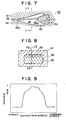
- a casting mold 30 for a ripper point is defined by casting molds 31 and 32, and a core 34, and forms a cavity 33 for a ripper point.
- a holding member 36 of a mild steel pipe has been filled with tungsten carbide particles as a hardened layer forming member (not illustrated), both ends thereof are scaled. Both of these ends are placed at a notch portion 34a of the core 34 and at a notch portion 32a of the casting mold 32, and are secured by a split surface 35 of the casting molds 31 and 32.
- These holding members 36 are provided at five points in the transverse direction (in Fig. 7, back-and-forth direction) of the ripper point.
- Molten steel of low-alloy cast steel is poured into the casting mold 30 with the above-described constitution and is cooled for solidification, as in the first embodiment.
- a ripper point 37 obtained in this way has a hardened layer 39 formed inside and a base material 38 having the characteristics of the components of molten steel formed outside, as Fig. 8 illustrates.
- Five circles formed by a two-dot chain line in the upper portion of the hardened layer 39 show the estimated locations of the holding members 36 before the molten steel is poured.
- Fig. 9 is a Vickers hardness distribution value on the line L2 on the section of the ripper point 37 illustrated in Fig. 8 from the surface P2 to the underside surface P3.
- the hardened layer 39 obviously has high hardness, and the hardness level at the hardest portion reaches about 850.
- the base material 38 has the hardness of about 400.
- the ripper point 37 which doesn't lose toughness on the surface and has extremely high hardness inside, is a wear resistant part with high strength.
- a typical heat treatment such as quenching, tempering, normalizing, or the like may be applied to a ripper point, if necessary.
- a casting mold 40 for an end bit is defined by casting molds 41 (forming an upper mold and not illustrated), and 42, and forms a cavity 43 for an end bit which is in the form of a plate.
- the inside of a holding member 44 of a soft steel pipe, to which the working of bending the steel along the shape of the end portion of this casting mold 42 is applied, is filled with a mixture of tungsten carbide particles and molybdenum carbide particles as a hardened layer forming member (not illustrated), and the holding member 44 is placed as in Fig. 10A and secured by the upper mold 41.
- Molten steel for steel casting is poured into the casting mold 40 with the above-described constitution, and is cooled for solidification, as in the first embodiment.
- An end bit 45 obtained by this method which has a hardened layer 46 formed on the end surface portion having a curved line as Fig. 10B illustrates, is a casting part having a hardened layer only in a portion where high hardness and wear resistance are desired. Further, a hardened layer can be formed on a desired curved surface by using a holding member to which a plurality of bend workings are applied.
- the present embodiment relates to constitutions, placement in casting molds, and sectional forms of the holding members in the above-described embodiments, as further application examples.
- a net-shaped structure 50 is defined by a plurality of holding members 51 filled with a hardened layer forming member.
- a contact portion 52 may be welded, brazed, bonded with an adhesive and so on, or wound with a fine thread such as a wire and so on.
- This net-shaped structure 50 is placed in a casting mold, corresponding to a desired position where a hardened layer is formed.
- the net-shaped structure 50 (50a) is placed on the ceiling portion of a casting mold 61 which is an upper mold of a casting mold 60.
- the net-shaped structure 50 (50b) is placed and secured between a casting surface 63 of the casting molds 61 and 62.
- the net-shaped structure 50 may be secured in a portion being formed such as notches of the casting molds 61 and 62, and so on, may be secured by a member such as an adhesive and so on, or may be secured by casting sand when a model is made.
- this net-shaped structure 50 By pouring specified molten steel into the casting mold 60 in which this net-shaped structure 50 (50a or 50b) is placed, a hardened layer 65 or 66 can be obtained. These hardened layers 65 and 66 are formed in a wide range, and have wear resistance with long lasting quality.
- This net-shaped structure 50 may be placed in layers, and may be formed into a desired shape such as a basket-shape and so on.
- the present invention is not limited to the above-described embodiments.
- the holding member filled with a hardened layer forming member the holding member with a circular section is described, but the shape of the section may be oval, polygonal, star-shaped, cylindrical, plate-shaped, in the shape of a curved surface, and so on, and may be selected according to the requirements.
- the hardened layer forming member graphite powder, and / or metallic powder such as nickel, copper, cobalt and so on may be added other than the sole use of superhard particles.
- one or more carbides selected from titanium carbide, boron carbide, chromium carbide, vanadium carbide, silicone carbide, and molybdenum carbide may be used other than tungsten carbide, or, superhard particles containing various kinds of alloy particles of the above-described carbide may be suitable.
- the wear resistant parts of the present invention are applicable to the parts requiring wear resistance and toughness, and may be used for the cutting parts of various excavating machines, gears, the connecting rods of internal-combustion engines and so on.
- the present invention whereby not only a hardened layer is partially formed in a desired position, but also a base material portion having characteristics of the molten steel components is formed, is useful as a method for casting wear resistant parts including both wear resistance and toughness.
Abstract
Description
- The present invention relates to a method for casting wear resistant parts, and particularly to a preferable method for casting wear resistant parts requiring a high degree of hardness.
- Conventionally, as a method for casting parts which aims at increasing the longevity of the parts by increasing the hardness of the parts required to have wear resistance, there is the following art.
- After casting a part in a specified form by using low-carbon steel, cementation is applied to increase the amount of carbon on the surface of the part, and the hardness on the surface is increased by quenching and so on. If necessary, tempering is conducted to make a wear resistant part having both wear resistance and toughness. It is known that a wear resistant part is made by casting by using medium carbon steel, and then after casting by conducting high-frequency induction hardening which can be performed in a short time.
- However, with the cementating method like this, the surface can be highly hardened with the hardness Hv as high as 850, and when a greater hardened depth is required, for example, when a depth of some 2 mm or more is needed, treatment takes an extremely long time, so that there is a disadvantage of the parts being expensive. In addition, in a high-frequency induction hardening method, it is necessary to produce a quenching coil for each casting part in every kind of form, and it is difficult to obtain a constant hardness and hardened depth except in the case of casting parts in a simple form.
- As another conventional art, by an insert-casting method including the steps of setting superhard chips on the surface in a casting mold and of pouring molten steel, the above-described chips are bonded and an extremely hard wear resistant part is obtained (refer to, for example, Japanese Patent Application Laid-open No. 2-187250). Wear resistance is obtained by setting a fine thread of high-alloy steel in the form of a net at a fixed seat provided in a casting mold, coating this fine thread with superhard alloy particles if necessary, and by pouring molten steel (refer to, for example, Japanese Patent Application Publication No. 3-28974).
- However, with this superhard chips insert-casting method, when an insert-casting portion with relatively low hardness is worn and the superhard chips are in the state of being exposed and so on, superhard chips with low toughness are damaged and broken by impactive load and so on, therefore there is a disadvantage of a short life of a part, even though superhard chips with extremely high hardness are provided. In the method using a fine thread of high-alloy steel, breakage and damage are rarely caused, but the method of holding superhard alloy particles in a specified portion is difficult and there is a disadvantage of a large number of man-hours required.
- Further, in Japanese Patent Application No. 6-34231 which is not made public, the applicant of the present invention proposes that wear resistant parts with high hardness are obtained by coating the surface of a casting mold with graphite powder and so on, then pouring molten steel to form a high carbonate hardened layer on the surface of the part, and by applying heat treatment if necessary.
- However, such a coating method, whereby the hardened depth is about 3 mm, has a disadvantage of being unable to form a thicker hardened layer.
- The present invention is made in order to eliminate the above-described disadvantage of the conventional art, and its object is to provide a method for casting wear resistant parts which is capable of forming a hardened layer at a desired position with ease, and which is preferable for producing casting parts having both wear resistance and toughness.
- The method for casting wear resistant parts relating to the present invention is a method for casting wear resistant parts partially including a superhard member, and is characterized by including the steps of filling the inside of a holding member which is molten into molten steel with a hardened layer forming member constituted by superhard particles, placing the holding member which has been filled with the hardened layer forming member in a casting mold, pouring molten steel into the casting mold, thereby causing the holding member to be molten into the molten steel with the superhard particles being dispersed, and solidifying the molten steel. The hardened layer forming member may be constituted by superhard particles, and graphite powder and / or metallic particles. Further, the holding member may be formed of a pipe made of mild steel which can be molten into molten steel.
- By this constitution, the holding member with superhard particles filled therein is molten into molten steel, so that the superhard particles contact the molten steel and disperse into the molten steel. Then a casting part obtained after solidification by cooling, has superhard particles dispersed on the surface and / or inside. Accordingly, the portion where the superhard particles are dispersed forms a hardened layer with high hardness while the portions other than the hardened layer have the characteristics of the components of molten steel, so that wear resistant parts having not only partially high hardness but also toughness can be manufactured.
- When graphite powder is added to superhard particles, the graphite powder diffuses as it is molten into molten steel when molten steel is poured, so that the portion in which the graphite powder diffuses becomes high-carbonate and has high hardness. By adding metallic particles such as various kinds of alloy particles and so on, the material can be partially adjusted since the metallic particles disperse as they are molten into molten steel.
- Further, by using a mild steel pipe as the holding member, the holding member can be easily placed in a desired position in the casting mold, and the size, form, and so on of the holding member, that is, the size, form, and so on of a state in which superhard particles are filled, can be selected according to the requirements, so that the position of a hardened layer and the area of a hardened layer can be controlled at will.
-
- Fig. 1 is a perspective view of the main part of a bucket for an excavating machine which is an example for the applications relating to the first and second embodiments of the present invention;
- Fig. 2 is an explanatory view of the section of the casting mold relating to the first embodiment;
- Fig. 3 is a schematic sectional view of the tooth relating to the first embodiment;
- Fig. 4 is a graph showing the distribution of the degree of hardness in the section after heat treatment is applied to the tooth relating to the first embodiment;
- Fig. 5 is an explanatory view of the section of the casting mold relating to the second embodiment of the present invention;
- Fig. 6 is a schematic sectional view of the tooth relating to the second embodiment;
- Fig. 7 is an explanatory view of the main section of the casting mold relating to the third embodiment of the present invention;
- Fig. 8 is a schematic sectional view of the ripper point corresponding to the Z to Z section in Fig. 7;
- Fig. 9 is a graph showing the distribution of the degree of hardness in the section of the ripper point relating to the third embodiment;
- Figs. 10A and 10B are diagrams explaining the end bit relating to the fourth embodiment of the present invention, and Fig. 10A is a transverse cross sectional view of the essential part of a casting mold for an end bit, while Fig. 10B is a schematic sectional view after casting;
- Fig. 11 is a perspective view of the net-shaped structure consisting of a plurality of holding members relating to the fifth embodiment of the present invention; and
- Fig. 12 is an explanatory view of the main section of the casting mold relating to the fifth embodiment.
- A preferable embodiment of the method for casting wear resistant parts relating to the present invention will be particularly described below with reference to the attached drawings.
- The first embodiment is the case in which the present invention is applied to a tooth which is a kind of cutting part of an excavating machine. In Fig. 1, a bucket 1 provided at the end of a working machine (not illustrated in the drawings) of construction machinery such as, for example, a hydraulic shovel which is one of the types of excavating machines includes a plurality of attaching
members 3 at the end portion of abucket body 2, and a plurality ofteeth 5 forming a cutting part are respectively attached to the attachingmembers 3 bypins 4. - In Fig. 2, a
casting mold 10 is defined bycasting molds 11 and 12, and forms acavity 13 for a tooth 5 (refer to Fig. 1). This casting mold 11 includes apouring gate 15 as well as acore 14 for the concave portion of thetooth 5. Molds for ordinary casting such as a green sand mold, a CO2 mold, a self-strengthening mold and so on are used for thesecasting molds 11 and 12. The casting mold 11 also includes a plurality of holdingmembers 16, and one part of theholding member 16 projects into acavity 13 with one part of theholding member 16 being buried in the casting mold 11. In this way, theholding member 16 can be placed at a specified position with ease and stability. Though a mild steel pipe is used for thisholding member 16, various kinds of metal such as steel, copper, nickel and so on, composite material, non-metal materials such as resin, and so on may be used as long as it can be molten into molten steel. - The inside of the above-described
holding member 16 is filled with a hardenedlayer forming member 19. In the present embodiment, both ends of the mild steel pipe are sealed after the mild steel pipe has been filled with the hardenedlayer forming member 19. This hardenedlayer forming member 19 is constituted by some 60 % by weight ofsuperhard particles 17 and some 40 % by weight ofgraphite powder 18, and tungsten cemented carbide (for example, W2 C) superhard alloy particles are used as thesuperhard particles 17. The super hard alloy particles in the present embodiment are mixed particles with particle diameters of some 0.1 to 0.7 mm. - With use of the
casting mold 10 of the above-described constitution, molten steel for steel casting is poured into thepouring gate 15. This cast steel may be typically composed, by using low-carbon steel with the amount of carbon being 0.2 % to 0.4 %, for example, SCCrM1, and the pouring temperature is about 1450 to 1600 ° C. When molten steel is poured, a mild steel pipe forming theholding member 16 becomes molten, and the hardenedlayer forming member 19 therein contacts the molten steel. Then, the tungsten cemented carbidesuperhard alloy particles 17 having a large specific gravity move mainly downwards and disperse as the surface thereof is slightly melted into the molten steel, while thegraphite powder 18 mainly goes into solid solution and diffuses. The dispersion and diffusion are completed by cooling and solidification of the molten steel, and a casting of thetooth 5 can be obtained. After solidification, the entire or part of thecasting mold 10 may be forcibly cooled by conducting air-cooling, water-cooling, and so on, depending on the requirements. - Fig. 3 illustrates a schematic section of the
tooth 5 obtained in the present embodiment, and a plurality of hardenedlayers 21 are partially formed. This hardenedlayer 21 corresponds to the portions of dispersion and diffusion of thesuperhard alloy particles 17 and the graphite powder 18 (refer to Fig. 2), and thetooth 5 is a casting part partially having hardened portions at desired positions. The amount of carbon on the sectional part of thetooth 5 is analyzed from the surface P1 to the inward direction along the line L1 by EPMA. Estimating from the analyses on data, there is a large amount of carbon in the portion from the surface P1 to the inside, and then the amount of carbon gradually decreases from the inside to the back equal to the amount of carbon in abase material 22. This casting part has a high-carbonate part from the surface to the inside withsuperhard alloy particles 17 dispersed so as to form thehardened layer 21 with a high degree of hardness, and the depth of the hardening is extremely large. Accordingly, this casting part not only has wear resistance with hardened layers partially formed, but also includes toughness since the other part is made of a base material with a relatively low degree of hardness. - When the
tooth 5 for heavier loads is further demanded, the degree of hardness may be increased by conducting the above-described forcible cooling, and if necessary, heat treatment is performed after solidification. For the heat treatment, a typical heat treatment such as quenching, tempering and so on can be applied, and in this embodiment, after heating to 950 ° C, oil quenching is conducted, then tempering at 200° C and air-cooling are conducted. As for thetooth 5 obtained by this method, the distribution of hardness on the section (on the same line as the line L1 in Fig. 3) measured with a Vickers hardness tester is illustrated in Fig. 4. As is clear from the drawing, the hardened depth is large being about 18 mm. According to the observation of the sectional structure, it is estimated that the surface portion up to a depth of about 3 mm has densely concentrated superhard alloy particles, and the area up to a depth of about 3 mm to about 11 mm has the dispersion of superhard alloy particles with a martensite as its base. Though the area further up to the depth of about 18 mm has decreasing amount of carbon, the area has martensite as its base. With the extremely high average hardness (Vickers hardness) of 804 at the portion where superhard alloy particles are densely concentrated, the present casting part has toughness as well as wear resistance with long lasting quality. - Then, the second embodiment of the method for casting wear resistant parts relating to the present invention will be described with reference to the drawings. The present embodiment is applied to the
tooth 5 of a cutting part of an excavating machine as an example for the applications, as in the first embodiment. - In Fig. 5, a casting
mold 24 defining a castingmold 20 includes a holdingmember 26, and one part of the holdingmember 26 projects into acavity 25 with one part of the holdingmember 26 being buried in the castingmold 24. The inside of the holdingmember 26 formed by bending a mild steel pipe into a substantially U-shaped form is filled with the hardenedlayer forming member 19, and the sealed portions are secured in the castingmold 24. These holdingmembers 26 are provided at three points in the castingmold 24 so as to be in parallel to the transverse direction of thetooth 5. - Molten steel for steel casting is poured into the casting
mold 20 with the above-described constitution and is cooled for solidification. Thetooth 5 obtained by this method has a hardenedlayer 28 formed in the position corresponding to the portions having the dispersion of thesuperhard alloy particles 17 and the diffusion of thegraphite powder 18, and a casting part having both wear resistance and toughness can be obtained as in the first embodiment. - Then, the third embodiment of the method for casting wear resistant parts relating to the present invention will be described with reference to the drawings. The present embodiment is applied to a ripper point which is a kind of cutting part for excavation of construction machinery.
- In Fig. 7, a casting
mold 30 for a ripper point is defined by castingmolds 31 and 32, and acore 34, and forms acavity 33 for a ripper point. After a holdingmember 36 of a mild steel pipe has been filled with tungsten carbide particles as a hardened layer forming member (not illustrated), both ends thereof are scaled. Both of these ends are placed at anotch portion 34a of thecore 34 and at anotch portion 32a of the casting mold 32, and are secured by asplit surface 35 of the castingmolds 31 and 32. These holdingmembers 36 are provided at five points in the transverse direction (in Fig. 7, back-and-forth direction) of the ripper point. - Molten steel of low-alloy cast steel is poured into the casting
mold 30 with the above-described constitution and is cooled for solidification, as in the first embodiment. Aripper point 37 obtained in this way has a hardenedlayer 39 formed inside and abase material 38 having the characteristics of the components of molten steel formed outside, as Fig. 8 illustrates. Five circles formed by a two-dot chain line in the upper portion of thehardened layer 39 show the estimated locations of the holdingmembers 36 before the molten steel is poured. - Fig. 9 is a Vickers hardness distribution value on the line L2 on the section of the
ripper point 37 illustrated in Fig. 8 from the surface P2 to the underside surface P3. Thehardened layer 39 obviously has high hardness, and the hardness level at the hardest portion reaches about 850. On the other hand, thebase material 38 has the hardness of about 400. As a result of the observation of the constitution, in thehardened layer 39, tungsten carbide is dispersed, and at the same time an increase in the amount of carbon, which is estimated to be a result from the decomposition of tungsten carbide, can be recognized. From the above, theripper point 37, which doesn't lose toughness on the surface and has extremely high hardness inside, is a wear resistant part with high strength. In addition, it is needless to say that a typical heat treatment such as quenching, tempering, normalizing, or the like may be applied to a ripper point, if necessary. - Next, the fourth embodiment of the method for casting wear resistant parts relating to the present invention will be described with reference to the drawings. The present embodiment is applied to an end bit forming a cutting part for earth-moving of construction machinery and so on.
- In Fig. 10A, a casting
mold 40 for an end bit is defined by casting molds 41 (forming an upper mold and not illustrated), and 42, and forms acavity 43 for an end bit which is in the form of a plate. The inside of a holdingmember 44 of a soft steel pipe, to which the working of bending the steel along the shape of the end portion of this castingmold 42 is applied, is filled with a mixture of tungsten carbide particles and molybdenum carbide particles as a hardened layer forming member (not illustrated), and the holdingmember 44 is placed as in Fig. 10A and secured by the upper mold 41. - Molten steel for steel casting is poured into the casting
mold 40 with the above-described constitution, and is cooled for solidification, as in the first embodiment. Anend bit 45 obtained by this method, which has a hardenedlayer 46 formed on the end surface portion having a curved line as Fig. 10B illustrates, is a casting part having a hardened layer only in a portion where high hardness and wear resistance are desired. Further, a hardened layer can be formed on a desired curved surface by using a holding member to which a plurality of bend workings are applied. - Then, the fifth embodiment of the method for casting wear resistant parts relating to the present invention will be described with reference to the drawings. The present embodiment relates to constitutions, placement in casting molds, and sectional forms of the holding members in the above-described embodiments, as further application examples.
- In Fig. 11, a net-shaped
structure 50 is defined by a plurality of holdingmembers 51 filled with a hardened layer forming member. When each holdingmember 51 is needed to be secured on one another, acontact portion 52 may be welded, brazed, bonded with an adhesive and so on, or wound with a fine thread such as a wire and so on. This net-shapedstructure 50 is placed in a casting mold, corresponding to a desired position where a hardened layer is formed. - For example, as Fig. 12 illustrates, when a hardened layer is formed on the upper side of a casting part, the net-shaped structure 50 (50a) is placed on the ceiling portion of a casting
mold 61 which is an upper mold of a castingmold 60. When a hardened layer is formed on the lower side of the casting part, the net-shaped structure 50 (50b) is placed and secured between a castingsurface 63 of the castingmolds structure 50 may be secured in a portion being formed such as notches of the castingmolds mold 60 in which this net-shaped structure 50 (50a or 50b) is placed, ahardened layer hardened layers structure 50 may be placed in layers, and may be formed into a desired shape such as a basket-shape and so on. - The method for casting wear resistant parts relating to the present invention is described in detail in the above, however, the present invention is not limited to the above-described embodiments. For example, as for the holding member filled with a hardened layer forming member, the holding member with a circular section is described, but the shape of the section may be oval, polygonal, star-shaped, cylindrical, plate-shaped, in the shape of a curved surface, and so on, and may be selected according to the requirements. As for the hardened layer forming member, graphite powder, and / or metallic powder such as nickel, copper, cobalt and so on may be added other than the sole use of superhard particles. As for these superhard particles, one or more carbides selected from titanium carbide, boron carbide, chromium carbide, vanadium carbide, silicone carbide, and molybdenum carbide may be used other than tungsten carbide, or, superhard particles containing various kinds of alloy particles of the above-described carbide may be suitable. In addition, the wear resistant parts of the present invention are applicable to the parts requiring wear resistance and toughness, and may be used for the cutting parts of various excavating machines, gears, the connecting rods of internal-combustion engines and so on.
- The present invention, whereby not only a hardened layer is partially formed in a desired position, but also a base material portion having characteristics of the molten steel components is formed, is useful as a method for casting wear resistant parts including both wear resistance and toughness.
Claims (3)
- A method for casting wear resistant parts partially including a superhard member, comprising the steps of:filling the inside of a holding member (16) which is molten into molten steel with a hardened layer forming member (19) constituted by superhard particles (17);placing the holding member (16) which has been filled with said hardened layer forming member (19) in a casting mold (10);pouring molten steel into said casting mold (10), thereby causing said holding member (16) to be molten into said molten steel with said superhard particles (17) being dispersed; andsolidifying said molten steel.
- The method for casting wear resistant parts according to Claim 1, wherein said hardened layer forming member (19) is constituted by the superhard particles (17), and graphite powder (18) and / or metallic particles.
- The method for casting wear resistant parts according to Claim 1 or Claim 2, wherein said holding member (16) is formed of a pipe made of mild steel which is molten into said molten steel.
Applications Claiming Priority (3)
| Application Number | Priority Date | Filing Date | Title |
|---|---|---|---|
| JP6123337A JP2852867B2 (en) | 1994-05-13 | 1994-05-13 | Method for producing wear-resistant parts and wear-resistant parts |
| JP123337/94 | 1994-05-13 | ||
| PCT/JP1995/000895 WO1995031304A1 (en) | 1994-05-13 | 1995-05-10 | Method for casting wear resistant parts |
Publications (2)
| Publication Number | Publication Date |
|---|---|
| EP0759336A1 true EP0759336A1 (en) | 1997-02-26 |
| EP0759336A4 EP0759336A4 (en) | 1997-03-12 |
Family
ID=14858076
Family Applications (1)
| Application Number | Title | Priority Date | Filing Date |
|---|---|---|---|
| EP95918164A Withdrawn EP0759336A1 (en) | 1994-05-13 | 1995-05-10 | Method for casting wear resistant parts |
Country Status (6)
| Country | Link |
|---|---|
| US (1) | US5785109A (en) |
| EP (1) | EP0759336A1 (en) |
| JP (1) | JP2852867B2 (en) |
| KR (1) | KR100201049B1 (en) |
| CN (1) | CN1048205C (en) |
| WO (1) | WO1995031304A1 (en) |
Families Citing this family (19)
| Publication number | Priority date | Publication date | Assignee | Title |
|---|---|---|---|---|
| US6033791A (en) * | 1997-04-04 | 2000-03-07 | Smith And Stout Research And Development, Inc. | Wear resistant, high impact, iron alloy member and method of making the same |
| US6916030B2 (en) * | 2002-12-06 | 2005-07-12 | Visteon Global Technologies, Inc. | Lightweight knuckle with in-cast spindle |
| JP4659344B2 (en) * | 2003-07-24 | 2011-03-30 | 富士重工業株式会社 | Manufacturing method of composite member |
| JP4859844B2 (en) * | 2005-12-20 | 2012-01-25 | 株式会社キトー | A heat treatment method for link chains with excellent low-temperature toughness |
| AU2008325291B2 (en) * | 2007-11-09 | 2013-10-24 | Hyperion Materials & Technologies (Sweden) Ab | Casted in cemented carbide components |
| SE532815C2 (en) * | 2007-11-09 | 2010-04-13 | Combi Wear Parts Ab | Self-sharpening, auto-signaling wear part |
| BE1018129A3 (en) * | 2008-09-19 | 2010-05-04 | Magotteaux Int | COMPOSITE IMPACTOR FOR PERCUSSION CRUSHERS. |
| KR100937341B1 (en) * | 2009-10-22 | 2010-01-20 | 주식회사 태강기업 | Grapple tooth for Crane-grab |
| EP2581468A1 (en) * | 2011-10-14 | 2013-04-17 | Siemens Aktiengesellschaft | Method for applying an anti-wear protective coating to a flow engine component |
| US10196712B2 (en) * | 2012-11-08 | 2019-02-05 | Sandvik Hyperion AB | Low carbon steel and cemented carbide wear part |
| JP6690991B2 (en) | 2016-05-17 | 2020-04-28 | 株式会社小松製作所 | Abrasion resistant part and its manufacturing method |
| US10745891B2 (en) * | 2018-02-27 | 2020-08-18 | Komatsu Ltd. | Tooth adapter and bucket |
| KR102279475B1 (en) * | 2018-10-10 | 2021-07-20 | 성보공업주식회사 | Device for casting bucket of excavator, preparation method for bucket of excavator using the same and bucket for excavator prepared therefrom |
| KR102483221B1 (en) * | 2018-10-10 | 2022-12-30 | 성보공업주식회사 | Tooth for bucket of excavator and preparation method thereof |
| MX2021011732A (en) * | 2019-03-27 | 2021-10-22 | Esco Group Llc | Lip for excavating bucket. |
| CN113290230B (en) * | 2020-02-24 | 2023-03-31 | 张丽芬 | Design method for pre-arranged hard surfaces and hard points of cast product and corresponding casting |
| AU2021254246B2 (en) * | 2020-04-09 | 2024-02-08 | Komatsu Ltd. | Wear-resistant component |
| JPWO2021205968A1 (en) * | 2020-04-09 | 2021-10-14 | ||
| US11882777B2 (en) | 2020-07-21 | 2024-01-30 | Osmundson Mfg. Co. | Agricultural sweep with wear resistant coating |
Citations (9)
| Publication number | Priority date | Publication date | Assignee | Title |
|---|---|---|---|---|
| US1374509A (en) * | 1919-10-10 | 1921-04-12 | Harold A Lomax | Art of hardening metal |
| DE672257C (en) * | 1936-11-11 | 1939-02-27 | Meutsch Voigtlaender & Co Vorm | Process for the production of workpieces which are provided with hard metal supports or inlays |
| DE2457449A1 (en) * | 1974-12-05 | 1976-06-10 | Wolfgang Gummelt | Composite castings with resistance to wear - made using motor vehicle ice tyre spikes as inexpensive cast insert |
| US4024902A (en) * | 1975-05-16 | 1977-05-24 | Baum Charles S | Method of forming metal tungsten carbide composites |
| EP0030933A1 (en) * | 1979-12-13 | 1981-06-24 | Vereinigte Edelstahlwerke Aktiengesellschaft (Vew) | Process for manufacturing metallic chilled castings and their use as teeth and/or lips for shovel excavators |
| JPS6455371A (en) * | 1987-08-26 | 1989-03-02 | Sumitomo Jukikai Chutan Kk | Production of composite material for drilling tooth |
| JPH02187250A (en) * | 1989-01-12 | 1990-07-23 | Kurimoto Ltd | Wear resistant complex casting material and manufacture thereof |
| JPH02268964A (en) * | 1989-04-12 | 1990-11-02 | Hitachi Ltd | Wear resisting pump parts and its manufacture |
| JPH07214288A (en) * | 1994-02-08 | 1995-08-15 | Komatsu Ltd | Surface hardening material of cast steel parts, casting mold and surface hardening method |
Family Cites Families (8)
| Publication number | Priority date | Publication date | Assignee | Title |
|---|---|---|---|---|
| US887648A (en) * | 1907-03-28 | 1908-05-12 | Philo Kemery | Process of alloying tungstein, molybdenum, &c., with iron and steel. |
| JPS51145429A (en) * | 1975-06-09 | 1976-12-14 | Kubota Ltd | Method of casting wearrproof steel |
| CA1107030A (en) * | 1977-12-01 | 1981-08-18 | Guido Perrella | Die-casting machine |
| JPS60196259A (en) * | 1984-03-15 | 1985-10-04 | Takaoka Kogyo Kk | Method for adding additive to molten metal |
| JPS60221166A (en) * | 1984-04-16 | 1985-11-05 | Komatsu Ltd | Production of wear-resistant composite material |
| JPS60261657A (en) * | 1984-06-08 | 1985-12-24 | Komatsu Ltd | Centrifugal casting method |
| SU1519837A1 (en) * | 1987-12-29 | 1989-11-07 | Институт проблем литья АН УССР | Method of manufacturing steel castings |
| JPH0328974A (en) * | 1989-06-27 | 1991-02-07 | Nec Corp | Automatic wiring designing device for printed circuit board |
-
1994
- 1994-05-13 JP JP6123337A patent/JP2852867B2/en not_active Expired - Fee Related
-
1995
- 1995-05-08 KR KR1019950011127A patent/KR100201049B1/en not_active IP Right Cessation
- 1995-05-10 US US08/737,477 patent/US5785109A/en not_active Expired - Fee Related
- 1995-05-10 CN CN95192959A patent/CN1048205C/en not_active Expired - Fee Related
- 1995-05-10 EP EP95918164A patent/EP0759336A1/en not_active Withdrawn
- 1995-05-10 WO PCT/JP1995/000895 patent/WO1995031304A1/en not_active Application Discontinuation
Patent Citations (9)
| Publication number | Priority date | Publication date | Assignee | Title |
|---|---|---|---|---|
| US1374509A (en) * | 1919-10-10 | 1921-04-12 | Harold A Lomax | Art of hardening metal |
| DE672257C (en) * | 1936-11-11 | 1939-02-27 | Meutsch Voigtlaender & Co Vorm | Process for the production of workpieces which are provided with hard metal supports or inlays |
| DE2457449A1 (en) * | 1974-12-05 | 1976-06-10 | Wolfgang Gummelt | Composite castings with resistance to wear - made using motor vehicle ice tyre spikes as inexpensive cast insert |
| US4024902A (en) * | 1975-05-16 | 1977-05-24 | Baum Charles S | Method of forming metal tungsten carbide composites |
| EP0030933A1 (en) * | 1979-12-13 | 1981-06-24 | Vereinigte Edelstahlwerke Aktiengesellschaft (Vew) | Process for manufacturing metallic chilled castings and their use as teeth and/or lips for shovel excavators |
| JPS6455371A (en) * | 1987-08-26 | 1989-03-02 | Sumitomo Jukikai Chutan Kk | Production of composite material for drilling tooth |
| JPH02187250A (en) * | 1989-01-12 | 1990-07-23 | Kurimoto Ltd | Wear resistant complex casting material and manufacture thereof |
| JPH02268964A (en) * | 1989-04-12 | 1990-11-02 | Hitachi Ltd | Wear resisting pump parts and its manufacture |
| JPH07214288A (en) * | 1994-02-08 | 1995-08-15 | Komatsu Ltd | Surface hardening material of cast steel parts, casting mold and surface hardening method |
Non-Patent Citations (6)
| Title |
|---|
| DATABASE WPI Section Ch, Week 7705 Derwent Publications Ltd., London, GB; Class M22, AN 77-08174Y XP002022318 & JP-A-51 145 429 (KUBOTA KK) , 15 December 1976 * |
| PATENT ABSTRACTS OF JAPAN vol. 013, no. 249 (C-605), 9 June 1989 & JP-A-01 055371 (SUMITOMO JUKIKAI CHIYUUTAN KK), 2 March 1989, & JP-B-03 028 974 22 April 1991 * |
| PATENT ABSTRACTS OF JAPAN vol. 014, no. 469 (M-1034), 12 October 1990 & JP-A-02 187250 (KURIMOTO LTD), 23 July 1990, * |
| PATENT ABSTRACTS OF JAPAN vol. 015, no. 025 (M-1071), 21 January 1991 & JP-A-02 268964 (HITACHI LTD), 2 November 1990, * |
| PATENT ABSTRACTS OF JAPAN vol. 95, no. 12, 26 December 1995 & JP-A-07 214288 (KOMATSU LTD), 15 August 1995, * |
| See also references of WO9531304A1 * |
Also Published As
| Publication number | Publication date |
|---|---|
| US5785109A (en) | 1998-07-28 |
| WO1995031304A1 (en) | 1995-11-23 |
| JP2852867B2 (en) | 1999-02-03 |
| KR950031322A (en) | 1995-12-18 |
| KR100201049B1 (en) | 1999-06-15 |
| CN1147778A (en) | 1997-04-16 |
| JPH07303956A (en) | 1995-11-21 |
| CN1048205C (en) | 2000-01-12 |
| EP0759336A4 (en) | 1997-03-12 |
Similar Documents
| Publication | Publication Date | Title |
|---|---|---|
| US5785109A (en) | Method for casting wear resistant parts | |
| US4608318A (en) | Casting having wear resistant compacts and method of manufacture | |
| JP2596106B2 (en) | Combined drilling tooth | |
| CA2455716C (en) | High-strength/high-toughness alloy steel drill bit blank | |
| US8043555B2 (en) | Cemented tungsten carbide rock bit cone | |
| EP0930949B1 (en) | Drill bit manufacturing method | |
| KR100783100B1 (en) | Tip for a buchket of an excavator and method for manufacturing the same | |
| US3885637A (en) | Boring tools and method of manufacturing the same | |
| KR870001312B1 (en) | Casting having wear resistant compacts & method of manufacture | |
| JP3380723B2 (en) | Drilling cutting blade and method of manufacturing the same | |
| EP0052584A1 (en) | A method of producing a steel body comprising hard material inserts | |
| JP2022527252A (en) | Drilling bucket lip | |
| JP3215568B2 (en) | Surface hardening material for cast steel products and surface hardening method | |
| AU2019228868B2 (en) | Tooth adaptor and bucket | |
| JP2003501268A (en) | Composite sacrificial components | |
| WO2021205969A1 (en) | Wear-resistant component | |
| CN115103946A (en) | Wear-resistant component | |
| JPH0328974B2 (en) | ||
| JPH0328973B2 (en) | ||
| KR100305856B1 (en) | Manufacturing method of wear resistant member | |
| PL244493B1 (en) | Method of producing tools with high surface resistance | |
| JPH0349658B2 (en) | ||
| JPH068498U (en) | Bit for shield cutter | |
| JPH1133699A (en) | Wear resistant cast body, and its manufacture | |
| JPH0681070A (en) | Wear resistant sintered compact and its production |
Legal Events
| Date | Code | Title | Description |
|---|---|---|---|
| PUAI | Public reference made under article 153(3) epc to a published international application that has entered the european phase |
Free format text: ORIGINAL CODE: 0009012 |
|
| 17P | Request for examination filed |
Effective date: 19961125 |
|
| AK | Designated contracting states |
Kind code of ref document: A1 Designated state(s): BE DE GB IT |
|
| A4 | Supplementary search report drawn up and despatched | ||
| AK | Designated contracting states |
Kind code of ref document: A4 Designated state(s): BE DE GB IT |
|
| GRAG | Despatch of communication of intention to grant |
Free format text: ORIGINAL CODE: EPIDOS AGRA |
|
| 17Q | First examination report despatched |
Effective date: 19980727 |
|
| GRAG | Despatch of communication of intention to grant |
Free format text: ORIGINAL CODE: EPIDOS AGRA |
|
| GRAH | Despatch of communication of intention to grant a patent |
Free format text: ORIGINAL CODE: EPIDOS IGRA |
|
| STAA | Information on the status of an ep patent application or granted ep patent |
Free format text: STATUS: THE APPLICATION IS DEEMED TO BE WITHDRAWN |
|
| 18D | Application deemed to be withdrawn |
Effective date: 19990223 |