EP0758615B1 - Dispositif de conditionnement et de distribution - Google Patents
Dispositif de conditionnement et de distribution Download PDFInfo
- Publication number
- EP0758615B1 EP0758615B1 EP96401755A EP96401755A EP0758615B1 EP 0758615 B1 EP0758615 B1 EP 0758615B1 EP 96401755 A EP96401755 A EP 96401755A EP 96401755 A EP96401755 A EP 96401755A EP 0758615 B1 EP0758615 B1 EP 0758615B1
- Authority
- EP
- European Patent Office
- Prior art keywords
- product
- dispensing
- container
- head
- valve
- Prior art date
- Legal status (The legal status is an assumption and is not a legal conclusion. Google has not performed a legal analysis and makes no representation as to the accuracy of the status listed.)
- Expired - Lifetime
Links
Images

Classifications
-
- B—PERFORMING OPERATIONS; TRANSPORTING
- B05—SPRAYING OR ATOMISING IN GENERAL; APPLYING FLUENT MATERIALS TO SURFACES, IN GENERAL
- B05B—SPRAYING APPARATUS; ATOMISING APPARATUS; NOZZLES
- B05B11/00—Single-unit hand-held apparatus in which flow of contents is produced by the muscular force of the operator at the moment of use
- B05B11/0005—Components or details
- B05B11/0062—Outlet valves actuated by the pressure of the fluid to be sprayed
- B05B11/007—Outlet valves actuated by the pressure of the fluid to be sprayed being opened by deformation of a sealing element made of resiliently deformable material, e.g. flaps, skirts, duck-bill valves
-
- B—PERFORMING OPERATIONS; TRANSPORTING
- B05—SPRAYING OR ATOMISING IN GENERAL; APPLYING FLUENT MATERIALS TO SURFACES, IN GENERAL
- B05B—SPRAYING APPARATUS; ATOMISING APPARATUS; NOZZLES
- B05B11/00—Single-unit hand-held apparatus in which flow of contents is produced by the muscular force of the operator at the moment of use
- B05B11/0005—Components or details
- B05B11/0027—Means for neutralising the actuation of the sprayer ; Means for preventing access to the sprayer actuation means
- B05B11/0029—Valves not actuated by pressure
-
- B—PERFORMING OPERATIONS; TRANSPORTING
- B05—SPRAYING OR ATOMISING IN GENERAL; APPLYING FLUENT MATERIALS TO SURFACES, IN GENERAL
- B05B—SPRAYING APPARATUS; ATOMISING APPARATUS; NOZZLES
- B05B11/00—Single-unit hand-held apparatus in which flow of contents is produced by the muscular force of the operator at the moment of use
- B05B11/0005—Components or details
- B05B11/0062—Outlet valves actuated by the pressure of the fluid to be sprayed
- B05B11/0072—A valve member forming part of an outlet opening
-
- B—PERFORMING OPERATIONS; TRANSPORTING
- B05—SPRAYING OR ATOMISING IN GENERAL; APPLYING FLUENT MATERIALS TO SURFACES, IN GENERAL
- B05B—SPRAYING APPARATUS; ATOMISING APPARATUS; NOZZLES
- B05B11/00—Single-unit hand-held apparatus in which flow of contents is produced by the muscular force of the operator at the moment of use
- B05B11/01—Single-unit hand-held apparatus in which flow of contents is produced by the muscular force of the operator at the moment of use characterised by the means producing the flow
- B05B11/10—Pump arrangements for transferring the contents from the container to a pump chamber by a sucking effect and forcing the contents out through the dispensing nozzle
- B05B11/1081—Arrangements for pumping several liquids or other fluent materials from several containers, e.g. for mixing them at the moment of pumping
- B05B11/1084—Arrangements for pumping several liquids or other fluent materials from several containers, e.g. for mixing them at the moment of pumping each liquid or other fluent material being pumped by a separate pump
-
- B—PERFORMING OPERATIONS; TRANSPORTING
- B65—CONVEYING; PACKING; STORING; HANDLING THIN OR FILAMENTARY MATERIAL
- B65D—CONTAINERS FOR STORAGE OR TRANSPORT OF ARTICLES OR MATERIALS, e.g. BAGS, BARRELS, BOTTLES, BOXES, CANS, CARTONS, CRATES, DRUMS, JARS, TANKS, HOPPERS, FORWARDING CONTAINERS; ACCESSORIES, CLOSURES, OR FITTINGS THEREFOR; PACKAGING ELEMENTS; PACKAGES
- B65D1/00—Rigid or semi-rigid containers having bodies formed in one piece, e.g. by casting metallic material, by moulding plastics, by blowing vitreous material, by throwing ceramic material, by moulding pulped fibrous material or by deep-drawing operations performed on sheet material
- B65D1/02—Bottles or similar containers with necks or like restricted apertures, designed for pouring contents
- B65D1/04—Multi-cavity bottles
-
- B—PERFORMING OPERATIONS; TRANSPORTING
- B65—CONVEYING; PACKING; STORING; HANDLING THIN OR FILAMENTARY MATERIAL
- B65D—CONTAINERS FOR STORAGE OR TRANSPORT OF ARTICLES OR MATERIALS, e.g. BAGS, BARRELS, BOTTLES, BOXES, CANS, CARTONS, CRATES, DRUMS, JARS, TANKS, HOPPERS, FORWARDING CONTAINERS; ACCESSORIES, CLOSURES, OR FITTINGS THEREFOR; PACKAGING ELEMENTS; PACKAGES
- B65D47/00—Closures with filling and discharging, or with discharging, devices
- B65D47/04—Closures with discharging devices other than pumps
- B65D47/20—Closures with discharging devices other than pumps comprising hand-operated members for controlling discharge
- B65D47/26—Closures with discharging devices other than pumps comprising hand-operated members for controlling discharge with slide valves, i.e. valves that open and close a passageway by sliding over a port, e.g. formed with slidable spouts
- B65D47/261—Closures with discharging devices other than pumps comprising hand-operated members for controlling discharge with slide valves, i.e. valves that open and close a passageway by sliding over a port, e.g. formed with slidable spouts having a rotational or helicoidal movement
- B65D47/263—Closures with discharging devices other than pumps comprising hand-operated members for controlling discharge with slide valves, i.e. valves that open and close a passageway by sliding over a port, e.g. formed with slidable spouts having a rotational or helicoidal movement between tubular parts
-
- B—PERFORMING OPERATIONS; TRANSPORTING
- B65—CONVEYING; PACKING; STORING; HANDLING THIN OR FILAMENTARY MATERIAL
- B65D—CONTAINERS FOR STORAGE OR TRANSPORT OF ARTICLES OR MATERIALS, e.g. BAGS, BARRELS, BOTTLES, BOXES, CANS, CARTONS, CRATES, DRUMS, JARS, TANKS, HOPPERS, FORWARDING CONTAINERS; ACCESSORIES, CLOSURES, OR FITTINGS THEREFOR; PACKAGING ELEMENTS; PACKAGES
- B65D81/00—Containers, packaging elements, or packages, for contents presenting particular transport or storage problems, or adapted to be used for non-packaging purposes after removal of contents
- B65D81/32—Containers, packaging elements, or packages, for contents presenting particular transport or storage problems, or adapted to be used for non-packaging purposes after removal of contents for packaging two or more different materials which must be maintained separate prior to use in admixture
- B65D81/3283—Cylindrical or polygonal containers, e.g. bottles, with two or more substantially axially offset, side-by-side compartments for simultaneous dispensing
- B65D81/3288—Cylindrical or polygonal containers, e.g. bottles, with two or more substantially axially offset, side-by-side compartments for simultaneous dispensing composed of two or more separate containers joined to each other
Definitions
- the present invention relates to a device for packaging and distribution of liquid, gelled products or pasty, and in particular, but not exclusively, a device for packaging and distribution of several products sun protection cosmetics, clues different protection.
- German patent application 24 44 227 a device for packaging and distributing two products liquids, including a two-compartment container for storing products separately, each compartment comprising a outlet for the product and the device comprising means for fixing a dispensing head to the container rotary to distribute the product contained in a selected compartment corresponding to an angular position predetermined head.
- the output of products are made through two respective distribution channels which emerge side by side.
- Such a device does not offer complete satisfaction, in particular because foreign bodies such as sand or dust can get into the container during the return of air which accompanies the return of the latter in its initial form after a product distribution.
- the other product contained in the associated distribution channel can dry or denature in contact with air.
- the object of the present invention is in particular to remedy the aforementioned drawbacks.
- a system of packaging and distribution of a liquid, gelled or pasty comprising a container with several compartments for store at least two products separately, each compartment comprising a product outlet mouthpiece, the device further comprising means for fixing to the container a rotating dispensing head for dispensing the product contained in a selected compartment corresponding to a predetermined angular position of the head, characterized by causes said dispensing head to have a single distribution fitted with a valve at the outlet end capable of open under the effect of the push of the product upstream, and by the fact that said dispensing head is shaped to establish a selective communication between the mouth of said compartment selected and said distribution channel and / or exert an action selective on product extraction means associated with said audit selected compartment.
- said valve is of the air return type.
- the product contained in the distribution channel is advantageously brought back by the suction which accompanies the return of the device in the initial state in the associated compartment. We avoid thus, during a subsequent distribution of the product contained in the other compartment, that the products of the two compartments mix in the distribution channel.
- the packaging and distribution system When the packaging and distribution system is used for the packaging of cosmetic products protection against sun exposure, the user can advantageously have under the appearance of a single bottle or tube of several products with different protection indices, or of a sun protection product and a after-sun such as a moisturizer.
- container should not be understood with any meaning restrictive, and includes any type of container, whether it is a single piece or formed by assembling several containers side by side elementary, in which case said compartments correspond in made to said basic containers.
- the head of rotary distribution can take an angular position of closure of the device in which said channel is isolated said mouths. Opening or closing the device by rotating the dispensing head without separation of parts, problems of loss of plug or entry foreign bodies which may hinder the closing, such as sand, encountered with the tubes or bottles of the prior art, are avoided.
- said means for fixing the dispensing head to the container have a cap having a tubular skirt external to click on the container and a neck for the rotational mounting of the head, the cap also being traversed by orifices communicating respectively in a sealed manner with said mouths of said compartments and opening into the interior of the neck in angularly spaced locations.
- these orifices are formed by recesses made on the face inside of the collar at its base and the cap has lips sealing rings engaging respectively in said mouthpieces when placed on the container.
- the container has at least one flexible wall shaped to allow the user to chase the product contained in a container compartment by pressure on this wall.
- said flexible wall is elastically deformable, and at rest has the shape of a half-sphere projecting from the outer surface of the container.
- said means for fixing the rotary dispensing head to the container allow axial movement of the head along its axis of rotation and said product outlet mouths are located on hollow control rods whose penetration acts on extraction means capable of causing a product to leave, the head having a bearing shaped so as to come to bear axial on only one control rod at a time.
- control rods are associated with respective pumps suitable for distribute each dose of the control rod a dose of product.
- said valve is produced by overmolding in an elastomeric material.
- the valve is located substantially in the continuity of the external surface of the dispensing head. So, the product that comes out of the valve during dispensing can accumulate on the external surface of the front distributor head to be removed by the user with his fingers or deposited directly on the region of the body on which the product must to be applied.
- a device as mentioned above is used to package and distribute two cosmetic products from sun protection, protection ratings or a protective product against exposure to sun and an after-sun.
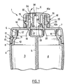
- FIG. 1 shows a device 1 for packaging and distribution in accordance with a first example of realization of the invention.
- This device 1 comprises a container 2 with two compartments 3, 4 intended to receive two creams of protection against sun exposure, of different indices.
- the container 2 is made by any technique of conformation of plastic material known per se, for example by injection blow molding or by extrusion and welding.
- the compartments 3 and 4 are separated by a partition 5 and open out at the end upper of container 2 by respective mouths 6, 7, parallel axes and circular cross section.
- the container 2 is supported on the outside to define a step 8 intended for fixing a cap 9.
- the latter covers the mouths 6, 7 and the connection area of the partition 5 at the top wall region of the container extending between these.
- the recess 8 is delimited radially inward by a tubular wall 10 on the outer surface from which is formed an annular groove 11.
- the latter is intended for snapping, that is to say snap-fastening, of a bead annular 12 of complementary shape projecting radially inward on a tubular skirt 13 made in part bottom of the cap 9.
- the tubular skirt 13 is connected superiorly on a wall 14 transverse to the axis of the skirt tubular 13, this wall 14 being extended above by a neck 15 of axis X used for mounting a tip or head 16 rotary distribution.
- the axes of the mouthpieces 6,7 are parallel to the X axis.
- the wall 14 is provided on its underside of annular sealing lips 17 and 18 adjusting so sealed respectively in the mouths 6 and 7 of the container 2.
- Recesses 19 and 20 are formed at the base of the neck 15 on its radially internal surface and appear in the example of embodiment described in the form of rectilinear oriented slots parallel to the X axis of the neck 15, opening at their end lower in the mouths 6 and 7 respectively and at their upper end in neck 15 at respective locations diametrically opposite.
- the dispensing nozzle 16 is delimited externally at its upper part by a wall 16 a in the shape of a dome and laterally by a tubular skirt 16 b and internally comprises two coaxial tubular skirts 21, 22 connecting at their upper end on the internal face of the wall 16 a .
- the tubular skirts 21 and 22 provide between them an annular space acting as a channel 23 for the passage of the product, opening at the upper end on the external face of the wall 16 a through a distribution orifice 24.
- the side wall 16 b is provided on its radially internal surface with an annular groove 25 snapped onto an annular bead 26 of complementary shape produced on the radially external surface of the neck 15.
- the tubular skirt 21, located between the wall 16b and the tubular skirt 22 is hollowed out at its periphery from its lower end edge to form an opening 27 for the passage of the product leaving the recess 19 or 20 (depending on the angular position of the dispensing nozzle 16) towards the channel 23.
- the dispensing orifice 24 is normally closed in the absence of product dispensing, by a valve 28, preferably of the air intake-type, made by overmolding an elastomeric material on the wall 16 a of dispensing nozzle 16.
- the transverse wall 14 has on its upper face a first annular sealing lip 29 internally bordering the radially internal surface of the tubular skirt 21 and a second annular sealing lip 30 extending between the tubular skirt 21 and the tubular skirt 22.
- the user turns the nozzle distribution 16 around the X axis to position the opening 27 of the tubular skirt 21 opposite the recess 19 or the recess 20 and distribute the product contained in the compartment 3 or compartment 4 respectively, or in a intermediate position to close the device.
- the user presses the wall of the container 2 delimiting this compartment to distribute the product contained in the latter, the valve 28 lifting under the effect of the pressure of the product.
- the valve 28 closes thanks to its own elasticity.
- the closing action of valve 28 is facilitated when the container 2 is made in one flexible, elastically deformable material thanks to the suction which supports the return of the container to its original shape. This suction makes it possible to avoid, during a subsequent distribution of the product contained in the other compartment, that the products from compartments 3 and 4 do not mix in channel 23.
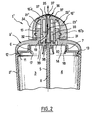
- FIG. 2 shows a device for packaging and distribution 1 'according to a second exemplary embodiment of the invention.
- the container 2 ' has roughly the same shape as the container 2 previously described and the cap 9 'differs from the above mainly by the shape of the inside of the neck 15.
- the cap 9 ' has inside a tubular skirt 31 cut out on two limited angular sectors of its periphery in diametrically opposite locations to form two product passage openings 32, 33.
- the dispensing nozzle 16 'rotatably mounted on the neck 15 around the axis X has an external side wall 16 b ' on which protrudes a rib 34 serving as an index to designate the selected compartment and an upper wall 16 a ' domed, crossed at its top by a central orifice 35 for the outlet of the product.
- a valve 36 made of elastomeric material is produced at the top of the wall 16 a 'by overmolding and it is cut in a star from its center to form several flexible blades 37 extending contiguously at rest to close the valve by absence of pressurization of the product upstream, able to deform by deviating outward under the effect of the pressure of the product to be dispensed.
- the dispensing nozzle 16 ′ internally comprises two coaxial tubular skirts 21 ′ and 22 ′ which are connected at the top on the internal face of the wall 16 a ′.
- the radially internal tubular skirt 22 internally forms a product passage channel 23' opening at its upper end onto the orifice 35 and it is perforated at its lower end over a limited sector of its periphery to form an opening 38 for passage of product to channel 23 '.
- the intermediate tubular skirt 21 ' fits tightly on the radially internal surface of the neck 15 above the recesses 19 and 20. It is perforated from its lower end edge over a limited angular sector of its periphery to forming an opening 39 for the passage of the product from the recesses 19 or 20 to the channel 23 '(after crossing the opening 32 or 33 and the opening 38).
- the user positions the index 34 on the side of compartment 3 or compartment 4 depending on the product selected.
- the opening 39 of the internal tubular skirt 21 ' is located then either between the recess 19 and the opening 32 adjacent to this last, either between the recess 20 and the opening 33 adjacent to this latest.
- the product is dispensed by pressing the wall of the container delimiting compartment 3 or compartment 4 selected.
- the product circulates through the recess 19 or 20, opening 39 and adjacent opening 32 or 33, opening 38 of the internal tubular skirt 22 'and reaches the dispensing orifice 35 by channel 23 '.
- the blades of the valve 37 move apart under the effect of product pressure. When the user stops pressing the container, the latter tends by elasticity to regain its shape initial and sucks the product contained in the channel 23 '.
- the user positions the tip distribution 16 'in an intermediate angular position in which the recesses 19 and 20 are isolated from the channel 23 '.
- FIG. 3 shows a device for 1 "packaging and distribution conforms to a third exemplary embodiment of the invention.
- the device 1 "comprises a container 2" housing two 3 "and 4" elementary containers loaded with two respectively products to be distributed separately, for example two protection against sun exposure of different indices.
- the containers 3 "and 4" are provided at their upper part with pumps 3 a “and 4 a ", known in themselves and shown diagrammatically, provided with respective hollow control rods 3 b “and 4 b ".
- Pumps 3 a “and 4a” can be of the type without return air and the containers 3 "and 4" of the type in which the product is packaged in a flexible pouch able to fold on itself in response to a product departure.
- the 2 "container has at its top a recess on the radially outer surface of which is formed an annular groove 11 "for mounting a 9" cap on the 2 “container with the possibility of sliding along a stroke predetermined parallel to the X axis.
- the 9 "cover has a 13 "tubular skirt provided in the vicinity of its end edge bottom of a 12 “annular bead engaging in the groove 11 "to hold the 9” cap on the 2 “container.
- the 9” cap is fitting onto the 2 “container by snapping.
- the tubular skirt 13 connects to its upper part on a transverse wall 14 "generally extending perpendicular to the X axis.
- the wall 14 is extended above by a 15" collar on which is rotatably mounted around the X axis a 16 "dispensing head.
- control rods 3 b “and 4 b “ pass through the wall 14 "through respective holes 19" and 20 “and open inside the neck 15" in a shoulder part 15 a “of the latter extending from its base and shaped to allow the control rods 3 b “and 4 b “ to slide parallel to the X axis.
- the head 16 "differs from the head 16 previously described with reference to FIG. 1 by the shape of the tubular skirt 21" in contact with the radially internal surface of the neck 15 ". More precisely, the tubular skirt 21" is shouldered at 21 a "in the lower part on half of its periphery to form with the shouldered part 15 a " of the neck 15 "a semi-annular groove 23" in which the control rods 3 b "or 4 b " can slide freely.
- the tubular skirt 21 is provided, on one half of its external circumference, with a rib 21 b " constituting a shaped surface for pressing axially on the end edge 3 c “or 4 c " of a control rod 3 b “or 4 b " when the cover 9 "is pressed onto the container 2".
- the channel formed inside the control rods is referenced 3 d “or 4 d “.
- the tubular skirt 21 has on its portion extending opposite the shoulder part 15 a " of the neck 15 “at least one opening 27", preferably located directly above the valve 28 fitted to the dispensing head 16 "16 "for the passage of the product leaving the control rod on which the tubular skirt 21" rests via the rib 21 b "towards the dispensing orifice equipped with the valve 28.
- the tubular skirt 21" is applied sealed, by its radially external annular surface located above the shoulder 21a ", on the radially internal annular surface of the neck 15" located above the shoulder part 15a ".
- the user turns the dispensing head 16 "to position the rib 21 b " on the side of the control rod 3 b “or 4 b “ depending on the product to distribute.
- the two control rods 3 b “and 4 b " are returned to their rest position, fully deployed, by elastic return means integrated into the pumps 3 a “and 3 b ".
- the cap 9 “comes, under the return action of the control rod pressing on the rib 21 b “, abutted by the boss 12 "against the upper end of the annular groove 11".
- the user presses on the dispensing head 16 "to slide the cover 9" down onto the container 2 ".
- the rib 21 b pressees on one of the control rods (the control rod 3b " in the example shown in FIG. 3) while the other control rod can penetrate freely into the annular groove 23 "and retains its deployed position rest.
- the depression of the control rod concerned causes the exit of a predetermined dose of product through the corresponding channel 3 d "or 4 d " which constitutes a compartment mouth within the meaning of the invention.
- the container used to package the products can present various forms and in particular be entirely walled flexible elastically deformable or, alternatively, with rigid wall for some parts and flexible wall for others.
- the flexible wall is advantageously shaped into a half-sphere protruding outward from the container at rest.
Landscapes
- Engineering & Computer Science (AREA)
- Mechanical Engineering (AREA)
- Ceramic Engineering (AREA)
- Closures For Containers (AREA)
- Containers And Packaging Bodies Having A Special Means To Remove Contents (AREA)
- Noodles (AREA)
- Manufacturing And Processing Devices For Dough (AREA)
Description
- la figure 1 est une vue en coupe axiale, partielle et schématique, d'un dispositif de distribution et de conditionnement conforme à un premier exemple de réalisation de l'invention,
- la figure 2 est une vue en coupe axiale, partielle et schématique, d'un dispositif de conditionnement et de distribution conforme à un deuxième exemple de réalisation de l'invention, et
- la figure 3 est une vue en coupe axiale, partielle et schématique, d'un dispositif de conditionnement et de distribution conforme à un troisième exemple de réalisation de l'invention.
Claims (13)
- Dispositif de conditionnement et de distribution de produits liquides, gélifiés ou pâteux,comprenant un récipient (2;2';2") à plusieurs compartiments (3,4;3";4") pour stocker séparément au moins deux produits, chaque compartiment (3;4;3";4") comportant une embouchure (6,7;3d",4d") de sortie du produit, le dispositif comprenant en outre des moyens de fixation (9;9';9") sur le récipient d'une tête de distribution rotative (16;16';16") permettant de distribuer le produit contenu dans un compartiment sélectionné correspondant à une position angulaire prédéterminée de la tête, caractérisé par le fait que ladite tête de distribution comporte un canal de distribution unique muni à l'extrémité de sortie d'un clapet apte à s'ouvrir sous l'effet de la poussée du produit en amont, et par le fait que ladite tête de distribution est conformée pour établir une communication sélective entre l'embouchure dudit compartiment sélectionné et ledit canal de distribution et/ou exercer une action sélective sur des moyens d'extraction (3a";4a") de produit associés audit compartiment sélectionné.
- Dispositif selon la revendication 1, caractérisé par le fait que ledit clapet est du type à reprise d'air.
- Dispositif selon l'une des revendications 1 et 2, caractérisé par le fait que ledit clapet se situe sensiblement dans la continuité de la surface externe de la tête de distribution.
- Dispositif selon l'une des revendications 1 à 3, caractérisé par le fait que ledit clapet (28 ; 37) est réalisé par surmoulage en une matière élastomère.
- Dispositif selon l'une des revendications 1 à 4, caractérisé par le fait que ladite tête de distribution est apte à prendre une position angulaire de fermeture dans laquelle le canal de distribution (23 ; 23';23") est isolé desdites embouchures (6,7).
- Dispositif selon l'une des revendications 1 à 5, caractérisé par le fait que lesdits moyens de fixation comportent une coiffe (9;9') présentant une jupe tubulaire externe (13;13') à claquer sur le récipient et un col (15) pour le montage à rotation de la tête de distribution (16;16'), la coiffe étant traversée par des orifices (19,20) communiquant respectivement de façon étanche avec lesdites embouchures (6,7) et débouchant à l'intérieur du col (15) des emplacements espacés angulairement.
- Dispositif selon la revendication 6, caractérisé par le fait que lesdits orifices (19;20) sont constitués par des évidements ménagés sur la face interne du col (15) à sa base.
- Dispositif selon l'une quelconque des revendications 6 ou 7, caractérisé par le fait que la coiffe (9;9') comporte des lèvres annulaires d'étanchéité (17,18) s'engageant respectivement à l'intérieur desdites embouchures (6,7) lorsque la coiffe est en place sur le récipient.
- Dispositif selon l'une quelconque des revendications 1 à 8, caractérisé par le fait que le récipient (2) présente au moins une partie de sa paroi qui est souple de manière à permettre à l'utilisateur de chasser le produit par pression sur cette paroi.
- Dispositif selon la revendication 9, caractérisé par le fait que ladite région de paroi qui est souple est élastiquement déformable.
- Dispositif selon la revendication 1 à 5, caractérisé par le fait que lesdits moyens de fixation (9") de la tête de distribution rotative (16") sur le récipient (2") autorisent un déplacement axial de la tête selon son axe de rotation (X) et par le fait que lesdites embouchures de sortie du produit (3d",4d") sont situées sur des tiges de commande creuses (3b", 4b") dont l'enfoncement agit sur des moyens d'extraction aptes à provoquer un départ de produit, la tête présentant une portée (21b") conformée de manière à venir en appui axial sur une seule tige de commande à la fois.
- Dispositif selon la revendication 11, caractérisé par le fait que lesdites tiges de commande sont associées à des pompes (3a", 4a") respectives aptes à distribuer à chaque enfoncement de la tige de commande une dose de produit.
- Utilisation d'un dispositif (1 ; 1' ; 1") selon l'une quelconque des revendications précédentes pour conditionner et distribuer deux crèmes de protection contre l'exposition au soleil, d'indices de protection différents.
Applications Claiming Priority (2)
| Application Number | Priority Date | Filing Date | Title |
|---|---|---|---|
| FR9509730 | 1995-08-10 | ||
| FR9509730A FR2737702B1 (fr) | 1995-08-10 | 1995-08-10 | Dispositif de conditionnement et de distribution |
Publications (2)
| Publication Number | Publication Date |
|---|---|
| EP0758615A1 EP0758615A1 (fr) | 1997-02-19 |
| EP0758615B1 true EP0758615B1 (fr) | 2000-03-22 |
Family
ID=9481868
Family Applications (1)
| Application Number | Title | Priority Date | Filing Date |
|---|---|---|---|
| EP96401755A Expired - Lifetime EP0758615B1 (fr) | 1995-08-10 | 1996-08-08 | Dispositif de conditionnement et de distribution |
Country Status (5)
| Country | Link |
|---|---|
| US (2) | US5833121A (fr) |
| EP (1) | EP0758615B1 (fr) |
| DE (1) | DE69607263T2 (fr) |
| ES (1) | ES2145404T3 (fr) |
| FR (1) | FR2737702B1 (fr) |
Cited By (2)
| Publication number | Priority date | Publication date | Assignee | Title |
|---|---|---|---|---|
| US7222752B2 (en) | 2002-12-20 | 2007-05-29 | L'oreal | Dispenser device including means that enable two substances to be dispensed in varying proportions |
| EP2614748A2 (fr) | 2006-05-05 | 2013-07-17 | L'Oréal | Dispositif de conditionnement et d'application |
Families Citing this family (43)
| Publication number | Priority date | Publication date | Assignee | Title |
|---|---|---|---|---|
| AUPO813297A0 (en) | 1997-07-21 | 1997-08-14 | Premium Pharmaceuticals Pty Limited | Package for a suncream |
| NL1007168C2 (nl) * | 1997-09-30 | 1999-03-31 | Sara Lee De Nv | Pomp en uitlaatmondstuk van pomp. |
| US6016916A (en) * | 1998-05-13 | 2000-01-25 | Ortner; Georg | Packaging unit for rod-shaped perfume bottles |
| US6161729A (en) * | 1998-12-14 | 2000-12-19 | Unilever Home & Personal Care Usa, Division Of Conopco | Dual chamber dispenser |
| FR2789371B1 (fr) * | 1999-02-05 | 2001-04-27 | Sofab | Distributeur de produits chimiquement instables |
| FR2799444B1 (fr) * | 1999-10-12 | 2001-12-14 | Oreal | Dispositif de distribution d une composition a gradient de concentration |
| US6398077B1 (en) | 2000-02-11 | 2002-06-04 | Seaquist Closures Foreign, Inc. | Package with multiple chambers and valves |
| DE20013287U1 (de) | 2000-08-02 | 2001-01-11 | MegaPlast GmbH & Co. KG, 78052 Villingen-Schwenningen | Selbsttätiger Verschluß für elastisch verformbare Behälter |
| US6655551B2 (en) | 2000-11-03 | 2003-12-02 | Joseph Manne | Portable dispenser for mixing and dispensing fluid mixtures |
| DE10064630A1 (de) * | 2000-12-22 | 2002-06-27 | Pfeiffer Erich Gmbh & Co Kg | Spender für Medien |
| US6834677B2 (en) * | 2002-04-30 | 2004-12-28 | Hewlett-Packard Development Company, L.P. | Over-molded check valves for fluid delivery systems |
| US6968982B1 (en) | 2002-09-18 | 2005-11-29 | Burns Caleb E S | Multiple-mist dispenser |
| US7210575B2 (en) * | 2002-09-26 | 2007-05-01 | Boehringer Ingelheim International Gmbh | Two-component packaging unit |
| US20060108363A1 (en) * | 2003-09-15 | 2006-05-25 | Yates William M Iii | Source selecting cap and closure for multiple chamber bottles |
| WO2006055508A2 (fr) * | 2004-11-15 | 2006-05-26 | Yates, William, M. | Capuchon selecteur de source et obturateur pour bouteilles a compartiments multiples |
| FR2877819B1 (fr) | 2004-11-15 | 2007-07-20 | Oreal | Dispositif de conditionnement et de distribution d'au moins deux compositions differentes. |
| US20060175350A1 (en) * | 2005-02-09 | 2006-08-10 | Abramson Andrew F | Multi-compartment container |
| DE102005021913A1 (de) * | 2005-05-09 | 2006-11-23 | Beiersdorf Ag | Sonnenschutzkit und Verfahren zur Pigmentierungsangleichung |
| USD543865S1 (en) | 2005-09-20 | 2007-06-05 | Walters Peter J | Dual dispenser package with dual actuators |
| USD543864S1 (en) | 2005-09-20 | 2007-06-05 | Cho Sean H | Dual dispenser package with single actuator |
| FR2900643B1 (fr) | 2006-05-05 | 2008-10-10 | Airlessystems Soc Par Actions | Organe de distribution de produit fluide et distributeur comprenant un tel organe de distribution |
| FR2909982B1 (fr) * | 2006-12-18 | 2011-03-18 | Valois Sas | Distributeur de produit fluide |
| FR2915373A1 (fr) | 2007-04-27 | 2008-10-31 | Oreal | Composition de soin et/ou de demaquillage de matiere(s) keratinique(s) |
| FR2917966B1 (fr) * | 2007-06-29 | 2009-10-02 | Oreal | Produit cosmetique de soin des matieres keratiniques |
| FR2919589B1 (fr) * | 2007-08-01 | 2009-11-13 | Airlessystems Soc Par Actions | Clapet d'obturation et procede pour fabriquer un tel clapet. |
| US8251263B2 (en) | 2008-03-24 | 2012-08-28 | Mary Kay Inc. | Container caps and systems |
| US9181005B2 (en) * | 2008-07-24 | 2015-11-10 | Mary Kay Inc. | Container caps and systems |
| KR200450616Y1 (ko) * | 2008-11-12 | 2010-10-15 | 박준혁 | 가압식 소스 배출용기 |
| DE102009022211A1 (de) | 2009-05-20 | 2010-12-02 | Heinrich, Hans-Werner, Prof. Dr. | Misch- und Abgabevorrichtung |
| US8800818B2 (en) | 2010-08-04 | 2014-08-12 | Evan Greenberg | Multi-chamber dispenser |
| FR2969921B1 (fr) | 2011-01-05 | 2013-08-09 | Oreal | Produit cosmetique en deux parties |
| GB2493923A (en) * | 2011-08-21 | 2013-02-27 | Iogi Ltd | Two-Stage Deodorant Applicator |
| ES2405434B1 (es) * | 2011-11-25 | 2014-04-07 | Pedro José LÓPEZ FABIÁN | Envase compartimentado y elemento dosificador. |
| DE202012004644U1 (de) * | 2012-05-11 | 2013-05-13 | Gerhard Brugger | Sprühspender fûr mehrere Komponenten |
| NL2009731C2 (en) | 2012-10-30 | 2014-05-06 | Heineken Supply Chain Bv | Container and valve for a container. |
| NL2009732C2 (en) | 2012-10-30 | 2014-05-06 | Heineken Supply Chain Bv | Beverage container and valve for a beverage container. |
| CA3288138A1 (en) | 2012-12-28 | 2025-11-29 | Kraft Foods Group Brands Llc | Containers and methods for isolating liquids prior to dispensing |
| FR3019532B1 (fr) | 2014-04-08 | 2017-10-06 | Qualipac Sa | Flacon, systeme comprenant un tel flacon et leur procede de fabrication. |
| KR101972213B1 (ko) * | 2017-05-12 | 2019-04-24 | 강성일 | 이종물질혼합용기 |
| US10584023B2 (en) * | 2018-06-29 | 2020-03-10 | Town & Country Linen Corp. | Multi reservoir dispenser |
| US10582786B1 (en) * | 2019-04-18 | 2020-03-10 | Alejandro Saint Geours | Double chamber bottle assembly |
| US12084258B1 (en) * | 2019-04-23 | 2024-09-10 | Brenda Bickford | Bottle apparatus |
| EP4252918B1 (fr) * | 2022-03-28 | 2025-07-16 | Aptar Radolfzell GmbH | Distributeur de liquide pourvu de deux réservoirs de liquide |
Family Cites Families (23)
| Publication number | Priority date | Publication date | Assignee | Title |
|---|---|---|---|---|
| BE429076A (fr) * | 1938-07-09 | 1938-08-31 | ||
| US830001A (en) * | 1906-03-20 | 1906-09-04 | Robert Pitt | Bottle. |
| FR429076A (fr) * | 1911-04-14 | 1911-09-14 | Otto Kasulke | Réfrigérateur |
| US1092433A (en) * | 1913-11-19 | 1914-04-07 | Virgil C Cox | Oil-can. |
| US2684789A (en) * | 1950-11-24 | 1954-07-27 | Injection Molding Company | Seal cap and dispensing nozzle for tubes or bottles |
| US3076573A (en) * | 1960-05-12 | 1963-02-05 | Bristol Myers Co | Dispensing closure |
| US3204836A (en) * | 1962-05-03 | 1965-09-07 | Park Plastics Co Inc | Dispenser |
| CH539551A (de) * | 1971-06-29 | 1973-07-31 | Dubach Hans | Vorrichtung an Behältern zur dosierten Abgabe eines flüssigen bis pastenförmigen Inhaltes |
| DE2444227A1 (de) * | 1974-09-16 | 1976-03-25 | Biolog Arval S A Sion Lab | Mehrkammerbehaelter |
| DE3011634A1 (de) * | 1980-03-26 | 1981-10-08 | Gerhart 3000 Hannover Daubner | Mehrkammer handspraydose mit verschliessbaren duesen, oder aushebbaren drehschieber |
| US4705192A (en) * | 1986-05-27 | 1987-11-10 | Knapton Paul A | Reusable multi-compartment container with charging and discharging means |
| US4949874A (en) * | 1987-12-04 | 1990-08-21 | Henkel Kommanditgesellschaft Auf Aktien | Device for dispensing at least two flowable substances |
| US4838457A (en) * | 1988-05-09 | 1989-06-13 | Swahl James C | Lotion blending and dispensing unit |
| US4893729A (en) * | 1988-07-08 | 1990-01-16 | Jerry R. Iggulden | Selectable mixing bottle |
| US5009342A (en) * | 1989-08-14 | 1991-04-23 | Mark R. Miller | Dual liquid spraying assembly |
| US4993594A (en) * | 1989-09-27 | 1991-02-19 | Piper Becker | Multi-constituent mixing and metering dispenser |
| FR2652567B1 (fr) * | 1989-10-04 | 1992-01-10 | Oreal | Dispositif de distribution comportant au moins un flacon a embout cassable. |
| FR2654016B1 (fr) * | 1989-11-06 | 1992-02-14 | Step Soc Tech Pulverisation | Poussoir melangeur doseur. |
| FR2654094B1 (fr) * | 1989-11-09 | 1993-07-09 | Aerospatiale | Procede de fabrication d'un materiau carbone protege contre l'oxydation par du nitrure d'aluminium et materiau obtenu par ce procede. |
| FR2697233B1 (fr) * | 1992-10-22 | 1995-01-27 | Lir France Sa | Distributeur à dosage variable pour produits fluides. |
| FR2711620B1 (fr) * | 1993-10-21 | 1995-12-22 | Oreal | Ensemble de distribution équipé d'un organe de fermeture unidirectionnel. |
| US5387200A (en) * | 1994-01-10 | 1995-02-07 | Sun-Safe Technologies Limited Partnership | Portable applicator for applying skin protection fluids |
| US5353964A (en) * | 1994-02-16 | 1994-10-11 | Liu Yin Peng | Twin-bottle nursing bottle |
-
1995
- 1995-08-10 FR FR9509730A patent/FR2737702B1/fr not_active Expired - Fee Related
-
1996
- 1996-07-29 US US08/688,166 patent/US5833121A/en not_active Expired - Lifetime
- 1996-08-08 EP EP96401755A patent/EP0758615B1/fr not_active Expired - Lifetime
- 1996-08-08 DE DE69607263T patent/DE69607263T2/de not_active Expired - Fee Related
- 1996-08-08 ES ES96401755T patent/ES2145404T3/es not_active Expired - Lifetime
-
2000
- 2000-11-13 US US09/709,714 patent/USRE38328E1/en not_active Expired - Fee Related
Cited By (2)
| Publication number | Priority date | Publication date | Assignee | Title |
|---|---|---|---|---|
| US7222752B2 (en) | 2002-12-20 | 2007-05-29 | L'oreal | Dispenser device including means that enable two substances to be dispensed in varying proportions |
| EP2614748A2 (fr) | 2006-05-05 | 2013-07-17 | L'Oréal | Dispositif de conditionnement et d'application |
Also Published As
| Publication number | Publication date |
|---|---|
| USRE38328E1 (en) | 2003-11-25 |
| FR2737702A1 (fr) | 1997-02-14 |
| US5833121A (en) | 1998-11-10 |
| DE69607263D1 (de) | 2000-04-27 |
| EP0758615A1 (fr) | 1997-02-19 |
| ES2145404T3 (es) | 2000-07-01 |
| DE69607263T2 (de) | 2000-11-02 |
| FR2737702B1 (fr) | 1997-09-26 |
Similar Documents
| Publication | Publication Date | Title |
|---|---|---|
| EP0758615B1 (fr) | Dispositif de conditionnement et de distribution | |
| EP0696479B1 (fr) | Dispositif de conditionnement d'un produit avec pompe manuelle de distribution en doses unitaires | |
| EP0410858B1 (fr) | Ensemble de distribution d'au moins un produit fluide, notamment cosmétique ou pharmaceutique | |
| EP0649795B1 (fr) | Ensemble de distribution équipé d'une soupape unidirectionnelle | |
| EP0410857B1 (fr) | Ensemble de distribution d'au moins un produit, notamment cosmétique, sous forme de crème, de liquide ou de poudre | |
| CA2286377C (fr) | Embout doseur et recipient equipe d'un embout doseur selon l'invention | |
| EP1514492B1 (fr) | Dispositif de conditionnement et de distribution d'un produit cosmétique. | |
| EP0335763B1 (fr) | Dispositif pour la distribution d'un mélange de substance pateuse et d'au moins un additif, notamment sous forme de cordon strié, et tête de distribution d'un tel dispositif | |
| EP0888823B1 (fr) | Distributeur pour un produit liquide ou pâteux comportant des moyens de pompage ameliorés | |
| EP0908395B1 (fr) | Tête de distribution à reprise d'air, et ensemble de conditionnement et de distribution équipé d'une telle tête | |
| EP0743263B1 (fr) | Dispositif de conditionnement et de distribution d'un produit liquide ou pâteux | |
| EP0753465B1 (fr) | Dispositif de conditionnement et de distribution d'un produit liquide ou pâteux avec applicateur en forme de dÔme | |
| CA2172229C (fr) | Distributeur de produit liquide ou pateux utilisable notamment en cosmetique | |
| EP1572375B1 (fr) | Pompe doseuse a actionnement manuel | |
| FR2750397A1 (fr) | Dispositif pour le stockage separe d'au moins deux produits, leur melange et la distribution du melange ainsi obtenu et procede de fabrication | |
| EP1165246B1 (fr) | Poche et ensemble de conditionnement et de distribution | |
| EP1472007B1 (fr) | Distributeur de produit liquide a pompe | |
| FR2824539A1 (fr) | Dispositif pour le conditionnement separe de deux produits, et leur distribution sous pression, de maniere separee ou en melange | |
| EP0764590B1 (fr) | Dispositif de conditionnement et de distribution | |
| FR2759986A1 (fr) | Recipient pour le conditionnement et la distribution d'un produit de consistance liquide a pateuse | |
| FR2786467A1 (fr) | Dispositif de distribution de produits liquides, fluides ou pateux | |
| FR2650562A1 (fr) | Ensemble de distribution d'un ou plusieurs produit(s) sous forme de creme, de liquide ou de poudre, notamment de produits cosmetiques | |
| FR2629058A1 (fr) | Dispositif pour la distribution d'un melange de substance pateuse et d'au moins un additif pateux, notamment sous forme de cordon strie, et tete de distribution d'un tel dispositif | |
| FR3154334A1 (fr) | Recharge de produit fluide | |
| CA3209439A1 (fr) | Dispositif de conditionnement a systeme d'aeration integre |
Legal Events
| Date | Code | Title | Description |
|---|---|---|---|
| PUAI | Public reference made under article 153(3) epc to a published international application that has entered the european phase |
Free format text: ORIGINAL CODE: 0009012 |
|
| AK | Designated contracting states |
Kind code of ref document: A1 Designated state(s): DE ES FR GB IT |
|
| 17P | Request for examination filed |
Effective date: 19970320 |
|
| 17Q | First examination report despatched |
Effective date: 19981001 |
|
| GRAG | Despatch of communication of intention to grant |
Free format text: ORIGINAL CODE: EPIDOS AGRA |
|
| GRAG | Despatch of communication of intention to grant |
Free format text: ORIGINAL CODE: EPIDOS AGRA |
|
| GRAH | Despatch of communication of intention to grant a patent |
Free format text: ORIGINAL CODE: EPIDOS IGRA |
|
| GRAH | Despatch of communication of intention to grant a patent |
Free format text: ORIGINAL CODE: EPIDOS IGRA |
|
| GRAA | (expected) grant |
Free format text: ORIGINAL CODE: 0009210 |
|
| AK | Designated contracting states |
Kind code of ref document: B1 Designated state(s): DE ES FR GB IT |
|
| REF | Corresponds to: |
Ref document number: 69607263 Country of ref document: DE Date of ref document: 20000427 |
|
| ITF | It: translation for a ep patent filed | ||
| REG | Reference to a national code |
Ref country code: ES Ref legal event code: FG2A Ref document number: 2145404 Country of ref document: ES Kind code of ref document: T3 |
|
| GBT | Gb: translation of ep patent filed (gb section 77(6)(a)/1977) |
Effective date: 20000614 |
|
| PLBE | No opposition filed within time limit |
Free format text: ORIGINAL CODE: 0009261 |
|
| STAA | Information on the status of an ep patent application or granted ep patent |
Free format text: STATUS: NO OPPOSITION FILED WITHIN TIME LIMIT |
|
| 26N | No opposition filed | ||
| REG | Reference to a national code |
Ref country code: GB Ref legal event code: IF02 |
|
| PGFP | Annual fee paid to national office [announced via postgrant information from national office to epo] |
Ref country code: DE Payment date: 20070802 Year of fee payment: 12 |
|
| PGFP | Annual fee paid to national office [announced via postgrant information from national office to epo] |
Ref country code: ES Payment date: 20070926 Year of fee payment: 12 |
|
| PGFP | Annual fee paid to national office [announced via postgrant information from national office to epo] |
Ref country code: GB Payment date: 20070809 Year of fee payment: 12 |
|
| PGFP | Annual fee paid to national office [announced via postgrant information from national office to epo] |
Ref country code: IT Payment date: 20070828 Year of fee payment: 12 |
|
| PGFP | Annual fee paid to national office [announced via postgrant information from national office to epo] |
Ref country code: FR Payment date: 20070808 Year of fee payment: 12 |
|
| GBPC | Gb: european patent ceased through non-payment of renewal fee |
Effective date: 20080808 |
|
| REG | Reference to a national code |
Ref country code: FR Ref legal event code: ST Effective date: 20090430 |
|
| PG25 | Lapsed in a contracting state [announced via postgrant information from national office to epo] |
Ref country code: IT Free format text: LAPSE BECAUSE OF NON-PAYMENT OF DUE FEES Effective date: 20080808 Ref country code: FR Free format text: LAPSE BECAUSE OF NON-PAYMENT OF DUE FEES Effective date: 20080901 Ref country code: DE Free format text: LAPSE BECAUSE OF NON-PAYMENT OF DUE FEES Effective date: 20090303 |
|
| REG | Reference to a national code |
Ref country code: ES Ref legal event code: FD2A Effective date: 20080809 |
|
| PG25 | Lapsed in a contracting state [announced via postgrant information from national office to epo] |
Ref country code: GB Free format text: LAPSE BECAUSE OF NON-PAYMENT OF DUE FEES Effective date: 20080808 |
|
| PG25 | Lapsed in a contracting state [announced via postgrant information from national office to epo] |
Ref country code: ES Free format text: LAPSE BECAUSE OF NON-PAYMENT OF DUE FEES Effective date: 20080809 |