EP0758265B1 - Reaktorböden fur einen vertikalen abgestuften polykondensationsreaktor - Google Patents
Reaktorböden fur einen vertikalen abgestuften polykondensationsreaktor Download PDFInfo
- Publication number
- EP0758265B1 EP0758265B1 EP95917097A EP95917097A EP0758265B1 EP 0758265 B1 EP0758265 B1 EP 0758265B1 EP 95917097 A EP95917097 A EP 95917097A EP 95917097 A EP95917097 A EP 95917097A EP 0758265 B1 EP0758265 B1 EP 0758265B1
- Authority
- EP
- European Patent Office
- Prior art keywords
- reactor
- tray
- liquid polymer
- flow
- outlet
- Prior art date
- Legal status (The legal status is an assumption and is not a legal conclusion. Google has not performed a legal analysis and makes no representation as to the accuracy of the status listed.)
- Expired - Lifetime
Links
- 238000006068 polycondensation reaction Methods 0.000 title description 4
- 229920000642 polymer Polymers 0.000 claims abstract description 119
- 239000007788 liquid Substances 0.000 claims abstract description 114
- 230000000712 assembly Effects 0.000 claims abstract description 27
- 238000000429 assembly Methods 0.000 claims abstract description 27
- 238000006116 polymerization reaction Methods 0.000 claims abstract description 14
- 239000012530 fluid Substances 0.000 claims description 10
- 238000010438 heat treatment Methods 0.000 claims description 7
- 230000003247 decreasing effect Effects 0.000 claims description 2
- 239000000126 substance Substances 0.000 claims description 2
- 239000006227 byproduct Substances 0.000 description 5
- 230000005484 gravity Effects 0.000 description 5
- 238000006243 chemical reaction Methods 0.000 description 4
- 239000010408 film Substances 0.000 description 4
- 239000000463 material Substances 0.000 description 3
- 238000000034 method Methods 0.000 description 3
- 230000008569 process Effects 0.000 description 3
- 230000015572 biosynthetic process Effects 0.000 description 2
- 239000011552 falling film Substances 0.000 description 2
- 230000014759 maintenance of location Effects 0.000 description 2
- 238000013019 agitation Methods 0.000 description 1
- 230000005540 biological transmission Effects 0.000 description 1
- 238000004140 cleaning Methods 0.000 description 1
- 230000005494 condensation Effects 0.000 description 1
- 238000009833 condensation Methods 0.000 description 1
- 238000010276 construction Methods 0.000 description 1
- 230000008602 contraction Effects 0.000 description 1
- 230000007423 decrease Effects 0.000 description 1
- 230000002950 deficient Effects 0.000 description 1
- 238000009826 distribution Methods 0.000 description 1
- 230000006872 improvement Effects 0.000 description 1
- 238000007689 inspection Methods 0.000 description 1
- 238000004519 manufacturing process Methods 0.000 description 1
- 230000007246 mechanism Effects 0.000 description 1
- 239000000155 melt Substances 0.000 description 1
- 238000012986 modification Methods 0.000 description 1
- 230000004048 modification Effects 0.000 description 1
- 239000000178 monomer Substances 0.000 description 1
- 230000000704 physical effect Effects 0.000 description 1
- 239000012429 reaction media Substances 0.000 description 1
- 239000010409 thin film Substances 0.000 description 1
Images


Classifications
-
- B—PERFORMING OPERATIONS; TRANSPORTING
- B01—PHYSICAL OR CHEMICAL PROCESSES OR APPARATUS IN GENERAL
- B01J—CHEMICAL OR PHYSICAL PROCESSES, e.g. CATALYSIS OR COLLOID CHEMISTRY; THEIR RELEVANT APPARATUS
- B01J19/00—Chemical, physical or physico-chemical processes in general; Their relevant apparatus
- B01J19/24—Stationary reactors without moving elements inside
-
- B—PERFORMING OPERATIONS; TRANSPORTING
- B01—PHYSICAL OR CHEMICAL PROCESSES OR APPARATUS IN GENERAL
- B01J—CHEMICAL OR PHYSICAL PROCESSES, e.g. CATALYSIS OR COLLOID CHEMISTRY; THEIR RELEVANT APPARATUS
- B01J19/00—Chemical, physical or physico-chemical processes in general; Their relevant apparatus
- B01J19/0053—Details of the reactor
- B01J19/006—Baffles
-
- B—PERFORMING OPERATIONS; TRANSPORTING
- B01—PHYSICAL OR CHEMICAL PROCESSES OR APPARATUS IN GENERAL
- B01J—CHEMICAL OR PHYSICAL PROCESSES, e.g. CATALYSIS OR COLLOID CHEMISTRY; THEIR RELEVANT APPARATUS
- B01J2219/00—Chemical, physical or physico-chemical processes in general; Their relevant apparatus
- B01J2219/00049—Controlling or regulating processes
- B01J2219/00051—Controlling the temperature
- B01J2219/00074—Controlling the temperature by indirect heating or cooling employing heat exchange fluids
- B01J2219/00076—Controlling the temperature by indirect heating or cooling employing heat exchange fluids with heat exchange elements inside the reactor
- B01J2219/00085—Plates; Jackets; Cylinders
-
- B—PERFORMING OPERATIONS; TRANSPORTING
- B01—PHYSICAL OR CHEMICAL PROCESSES OR APPARATUS IN GENERAL
- B01J—CHEMICAL OR PHYSICAL PROCESSES, e.g. CATALYSIS OR COLLOID CHEMISTRY; THEIR RELEVANT APPARATUS
- B01J2219/00—Chemical, physical or physico-chemical processes in general; Their relevant apparatus
- B01J2219/00049—Controlling or regulating processes
- B01J2219/00051—Controlling the temperature
- B01J2219/00132—Controlling the temperature using electric heating or cooling elements
- B01J2219/00135—Electric resistance heaters
-
- B—PERFORMING OPERATIONS; TRANSPORTING
- B01—PHYSICAL OR CHEMICAL PROCESSES OR APPARATUS IN GENERAL
- B01J—CHEMICAL OR PHYSICAL PROCESSES, e.g. CATALYSIS OR COLLOID CHEMISTRY; THEIR RELEVANT APPARATUS
- B01J2219/00—Chemical, physical or physico-chemical processes in general; Their relevant apparatus
- B01J2219/00049—Controlling or regulating processes
- B01J2219/00164—Controlling or regulating processes controlling the flow
- B01J2219/00166—Controlling or regulating processes controlling the flow controlling the residence time inside the reactor vessel
-
- B—PERFORMING OPERATIONS; TRANSPORTING
- B01—PHYSICAL OR CHEMICAL PROCESSES OR APPARATUS IN GENERAL
- B01J—CHEMICAL OR PHYSICAL PROCESSES, e.g. CATALYSIS OR COLLOID CHEMISTRY; THEIR RELEVANT APPARATUS
- B01J2219/00—Chemical, physical or physico-chemical processes in general; Their relevant apparatus
- B01J2219/00049—Controlling or regulating processes
- B01J2219/00168—Controlling or regulating processes controlling the viscosity
-
- B—PERFORMING OPERATIONS; TRANSPORTING
- B01—PHYSICAL OR CHEMICAL PROCESSES OR APPARATUS IN GENERAL
- B01J—CHEMICAL OR PHYSICAL PROCESSES, e.g. CATALYSIS OR COLLOID CHEMISTRY; THEIR RELEVANT APPARATUS
- B01J2219/00—Chemical, physical or physico-chemical processes in general; Their relevant apparatus
- B01J2219/00761—Details of the reactor
- B01J2219/00763—Baffles
- B01J2219/00765—Baffles attached to the reactor wall
- B01J2219/00777—Baffles attached to the reactor wall horizontal
Definitions
- This invention relates to a vertically disposed polymerization reactor having a series of essentially circular tray assemblies; each tray assembly having a central open vapor chimney and a single flow path composed of at least two loops wherein the liquid polymer flow is reversed by means of a substantially semi-circular turnaround wall; said trays having a liquid polymer tray inlet and a liquid polymer tray outlet for conducting a flow of the liquid polymer by means of a hydraulic gradient; each tray assembly being open at the top for escape of vapor from the liquid polymer flow to the central open vapor chimney; and said trays arranged in vertical disposition one above the other.
- Tray designs for vertical oriented polymerization reactors usually employ gravity and vertical drop to achieve the desired degree of polymerization without the complexities of mechanical agitation.
- the polymeric melt cascades down the inside of the vertical length of the reaction vessel.
- Baffles or trays are mounted in the vessel to provide retention of the polymer melts, thereby increasing liquid residence time within the reactor and its exposure to the reaction conditions.
- the liquid residence time is required to allow sufficient time for the polymerization kinetics to keep up with the enhanced byproduct liberation rates achieved by the increase in the liquid-vapor surface area and the enhancement of its renewal.
- U.S. Pat Nos. 4,196,168, 3,841,836, 3,509,203, 3,359,074 and 3,787,479, and Great Britain Pat. No. 1320769 disclose reactors wherein the reacting media flows by hydraulic gradient.
- U.S. Pat No. 4,196,168 discloses a vertical polymerization reactor having a series of downwardly sloping rectangular trays for conducting a flow of liquid polymer in a descending path.
- U.S. Pat No. 3,841,836 discloses a vertical polycondensation reactor having a series of downwardly sloping adjustable rectangular trays and a means for continuously sensing the viscosity of the polymer.
- U.S. Pat No. 3,509,203 discloses a vertical reactor having a series of horizontal structures in cascade arrangement which contain a plurality of annular passages in each tray for horizontal flow of the liquid polymer therethrough and a connecting tube from the center of each horizontal structure for downward travel of the liquid polymer.
- Disadvantages associated with the reactor disclosed in U.S. Pat No. 3,509,203 are that the flow path is too long for high viscosity materials, corners in the flow path are sources of stagnant flow regions, the roof inhibits vapor transmission and adds unnecessarily to the complexity of construction, and the tubes for flow between the trays prevent the free flow of a film which would enhance the liberation of vapor.
- U.S. Pat No. 3,359,074 discloses a vertical polycondensation reactor having a series of circular trays containing substantially equally spaced, chordwise extending slots. The slots are operative to generate the necessary surface renewal within the relatively more viscous fluid medium passing therethrough. Disadvantages associated with the reactor disclosed in U.S. Pat No. 3,359,074 are that there is no positive hold-up volume on the trays, the residence time is controlled by fluid viscosity and flow rate, and the slots must be sized accurately for a particular liquid rate and liquid physical properties or the tray could flood or completely drain out. In addition, the vapor flow control mechanism is subject to plugging.
- U.S. Pat No. 3,787,479 discloses a vertical reactor having a series of circular trays with transverse baffles creating several approximately rectangular segments. Thus, the trays contain an elongated side-to-side flow path for plug-like flow of the reaction medium from one side of the tray to the other. Disadvantages associated with the reactor disclosed in U.S. Pat No. 3,787,479 are that corners in the flow path are sources of stagnant flow regions, and the tubes for flow between the trays prevent the formation of a free-flowing film to enhance the liberation of vapor.
- Great Britain Pat. No. 1320769 discloses a reactor having substantially horizontal spiral flow channels, open along the top wherein the side walls of the spiral flow channel are constructed as closed flow ducts. Disadvantages associated with the reactor disclosed in Great Britain Pat. No. 1320769 are that the use of horizontal spiral flow channels without reverse turnarounds prevents the equalizing of flow paths and the "inside" track is shorter than the "outside” track. In addition, the use of only one tray greatly limits the available free surface area, and prevents the formation of a free-falling film between trays which enhances the liberation of vapor.
- references are deficient in that they include either (a) stagnant flow regions caused by material being bypassed by material flowing within a shorter-path streamline, or (b) poor utilization of the circular space within horizontal cross-section of a vertically oriented cylindrical vessel.
- the reactor of the present invention utilizes a circular tray which efficiently utilizes the cross-sectional area of a cylindrical reactor while providing uniform liquid polymer melt flow path lengths which minimize stagnant flow or dead zone regions.
- the reactor of the present invention is able to process high viscosity liquids and provide controlled residence time (liquid volumetric holdup) for the occurrence of chemical reactions.
- the reactor of the present invention is designed to allow vapor traffic to escape each tray and travel to the reactor's vapor outlet along a path external to the path of the polymer flow.
- tray design which contains channels that reverse the flow of a liquid by approximately 180° in order to obtain similar flow path lengths along the flow streamlines without the presence of stagnant flow regions or eddies.
- a polymerization reactor (2) having a vertically disposed outer shell (4), a liquid polymer reactor inlet (6) near the top of the reactor, and a liquid polymer reactor outlet (8) at the bottom of the reactor, comprising a series of essentially circular flat or downward sloping tray assemblies (10) which are fully enclosed within said reactor vessel (2);
- the present invention relates to a vertically disposed polymerization reactor having a series of essentially circular tray assemblies.
- the polymerization reactor 2 has a vertically disposed shell 4, a liquid polymer reactor inlet 6 near the top of the shell 4 for entrance of a liquid polymer into the reactor 2, a vapor outlet 9, and a liquid polymer reactor outlet 8 at the bottom of the shell 4 for exit of the liquid polymer from the reactor 2.
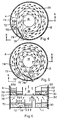
- the improvement in the polymerization reactor 2 is in the series of essentially circular tray assemblies 10 which are fully enclosed within said reactor 2. Enclosure of the outer perimeter of the tray assemblies 10 may be either the shell 4 of the reaction vessel 2 or a separate enclosure wall 12 which prevents liquid polymer from splattering out and over the perimeter of the tray assemblies 10. As set forth in FIG. 2, the tray assemblies 10 have a liquid polymer tray inlet 14 and a liquid polymer tray outlet 16. Each tray assembly 10 has a central open vapor chimney 18 bounded by an inner wall 20.
- Liquid polymer flows over a tray floor 11 along a single uniform cross-section flow path 26 enclosed by means of an outer wall 12, an inner wall 20, a middle wall 22 between the outer wall 12 and the inner wall 20, and a semi-circular turnaround wall 24.
- the walls have sufficient height to prevent spillage of the liquid polymer.
- the tray floor 11 may be flat or have a downward sloping floor and/or vertical falls. Such features of the tray floor may be adjustable to provide control of the depth of liquid polymer on the tray. Increasing the angle of the downward sloping floor and/or increasing the frequency of vertical falls results in shallow polymer depths which rapidly liberate byproducts.
- the cross-sectional flow path 26 is composed of at least two loops, an inner loop 30 and an outer loop 32.
- the loops may be concentric.
- the liquid polymer flows from one loop to the other by means of a substantially semi-circular turnaround wall 24 which results in the flow direction of the liquid polymer being reversed.
- the width 34 of the cross-sectional flow path 26 is decreased by up to 40% by means of a flow restrictor element 36 near the centerpoint of the arc of the semi-circular turnaround wall 24.
- the flow restrictor element 36 can be an extension of the middle wall 22, a vertical cylinder, such as a circular cylinder, attached to the end of the middle wall 22, or other bluff body having a vertical axis.
- the middle wall 22 can be tapered into the flow restrictor element. More preferably, the width of the cross-sectional flow path 34 is 20% to 30% less than the width of the cross-sectional flow path 26 in the inner loop 30 and outer loop 32.
- the flow restrictor element 36 causes a gradual temporary contraction in the width of the cross-sectional flow path 26 and subsequent gradual expansion to the original width of the cross-sectional flow path 26.
- the flow restrictor element lengthens the section of the middle wall 22 within the region of the semicircular turnaround wall 24 to at least 20% of the length of the outer semicircular turnaround wall 24.
- the liquid polymer flows around the inner loop 30 to the tray outlet 16.
- Prior to the tray outlet 16 preferably, is an outlet weir 40.
- the polymer flows over and or through the outlet weir 40 which controls the depth of liquid polymer on the tray assembly 10.
- the liquid polymer flows from upper tray assemblies 10 to lower tray assemblies 10 by means of gravity.
- the outlet weir 40 is of such length that as the liquid polymer flows over or through the outlet weir 40, the liquid polymer is sheared into a thin film.
- the thinning process shears small bubbles of vaporized byproducts and releases that portion of the byproducts trapped in bubbles which would otherwise be too small to break free of the viscous liquid polymer.
- the polymer flows from one tray to the tray below as a free falling film which enhances the liberation of vapor.
- the liberation of byproducts which are removed as vapor is necessary in the polycondensation process in order to drive the molecular build up of the polymer.
- Flow of the liquid polymer is accomplished by means of a hydraulic gradient wherein the height of fluid surface at the liquid polymer tray inlet 14 is greater than the height of fluid surface at the outlet weir 40.
- the high velocity of the liquid polymer compared with rectangular single-pass trays, washes the flow channel which minimizes buildup of polymer on the channel walls and reduces the potential for stagnant flow regions or eddies.
- the high velocity improves heat transfer effectiveness which decreases resistance to the transfer of thermal energy and eliminates overcooking of the polymer in localized hot-spots.
- the tray assemblies 10 may contain a means for heating liquid monomer or polymer. Suitable heating means include electric resistance, steam, and heat transfer medium chemicals. Preferably, the heating means is uniform and is located on the bottom side of the tray assemblies 10. A preferred heating means is the use of a heat transfer liquid in half pipe jackets which are secured to the bottom side of the tray assemblies 10.
- the liquid polymer from an upper tray assembly outlet flows into an inlet region of a lower tray assembly.
- the inlet region is within either the outer loop 32 or the inner loop 30 of the tray assembly 10.
- the liquid polymer enters the outer loop 32 through the liquid polymer tray inlet 14, as shown in FIG. 2, the liquid polymer flows in the flow path 26 through a redistribution weir 42 in the outer loop 32.
- the liquid polymer is prevented from flowing in two directions in the flow path 26 because of a sloping inlet floor having a back wall 46.
- the liquid polymer flows along the outer loop 32 until the liquid polymer flow is reversed into the inner loop 30 by means of a substantially semi-circular turnaround wall 24.
- the flow of the liquid polymer in the inner loop 30 is continued until the liquid polymer passes over and/or through an outlet weir 40 into the tray outlet 16 for flow by gravity to a lower tray assembly 10 of the tray immediately below.
- the liquid polymer flows in the flow path 26 through a redistribution weir 52 in the inner loop 30.
- the liquid polymer is prevented from flowing in two directions in the flow path 26 because of a sloping inlet floor having a back wall 56.
- the liquid polymer flows along the inner loop 30 until the liquid polymer flow is reversed into the outer loop 32 by means of a substantially semi-circular turnaround wall 24.
- the flow of the liquid polymer in the outer loop 32 is continued until the liquid polymer passes over and/or through an outlet weir 58 into the tray outlet 60 for flow by gravity to a lower tray assembly 10 of the tray immediately below.
- each tray assembly 10 is composed of two loops, an inner loop and outer loop, and all the tray assemblies are essentially identical.
- the inner loop extends to the outer wall of the tray assembly, and the inner wall of the inner loop is tangent to the central vapor chimney and to the semicircular turn around wall, and the flow of liquid polymer on each tray assembly 10 proceeds from outside of the tray to the inside of the tray.
- the liquid polymer enters the outer loop 32 through the tray inlet 70 and flows through a redistribution weir 74 in the flow path 26.
- a sloped entry 72 is recommended at the tray inlet 70 to prevent stagnant flow regions in the flow path 26.
- the orientation of the tray assemblies 10 could be designed in a similar manner so that the liquid polymer flows from the inside of the tray to the outside of the tray, however, this would result in a greater probability of the liquid polymer splashing or spilling into the central vapor chimney 18.
- Lower tray assemblies are rotated relative to the preceding upper tray assembly.
- a lower tray assembly 10 is rotated 22° to 62° if the central open vapor chimney 18 diameter is one third of the reactor vessel diameter, more preferably 24° to 34° about a vertical axis at the tray centerpoint relative to an upper tray assembly 10.
- the lower tray assembly is rotated relative to the preceding upper tray assembly in order that liquid polymer flowing over or through the outlet weir 76 of the upper tray outlet 78, falls vertically into the tray inlet 70 of the lower tray assembly, as shown in FIG. 4 and in FIG. 5.
- the relative angle of rotation between successive trays should be kept to a minimum so that liquid polymer falls into the inlet of a lower tray and stagnant zones opposite the direction of flow on the lower tray are minimized.
- the outlet weir 76 is enlarged over the previous outlet weir 58 and results in a thinner film falling between trays.
- the tray outlet weir 76 preferably, is positioned at an angle so that the length over which liquid polymer flows is maximized.
- the angle of rotation of successive trays is, preferably, approximately equal to the angle of the tray outlet and weir to the direction of flow so that the overflow edge projects parallel to the middle wall of the tray below. More preferably, the angle of rotation and outlet weir angle relative to the direction of flow are 24° to 34°.
- the tray outlet 78 overflow edge is aligned a short distance away from the wall(s) of the lower tray to prevent liquid polymer from flowing down the wall(s).
- Each tray assembly 10 may be open at the top for escape of vapor from the liquid polymer over the middle wall 22 and/or inner wall 20 and then radially to the central vapor chimney 18. In contrast, each tray assembly 10 may be closed at the top to force the vapor to move cocurrently to the flow of liquid polymer through the tray outlet 16.
- the tray assemblies 10 extend to said outer shell 4 in vertical disposition one above the other. In the case where the trays are open at the top, the tray assemblies 10 are far enough apart to allow for vapor to escape and the walls are shallow enough to allow for vapor to escape. The vapor thus escapes along paths that do not interfere with the liquid polymer flow paths.
- Vapor from the tray assemblies 10 collects in the central open vapor chimney 18 and is channeled along the central open vapor chimney 18 to the vapor outlet 9 of the reactor vessel 2.
- the central open vapor chimney 18 encompasses 1 to 25 percent, preferably 6 to 12 percent, of the total cross-sectional area of each tray.
- the exact size of the central open vapor chimney 18 for a specific reactor vessel 2 is dependant on the size of the reactor vessel 2 and the vapor volumetric flow rate. On large reactor columns, the central open vapor chimney 18 can be used to provide access for inspection, cleaning, and modifications.
Landscapes
- Chemical & Material Sciences (AREA)
- Organic Chemistry (AREA)
- Chemical Kinetics & Catalysis (AREA)
- Other Resins Obtained By Reactions Not Involving Carbon-To-Carbon Unsaturated Bonds (AREA)
- Polyesters Or Polycarbonates (AREA)
- Physical Or Chemical Processes And Apparatus (AREA)
- Polymerisation Methods In General (AREA)
- Polyoxymethylene Polymers And Polymers With Carbon-To-Carbon Bonds (AREA)
- Transition And Organic Metals Composition Catalysts For Addition Polymerization (AREA)
Claims (20)
- Polymerisationsreaktor (2) mit einem senkrecht angeordneten äußeren Gehäuse (4), einem Reaktoreinlaß für flüssiges Polymer (6) in der Nähe des oberen Endes des Reaktors, einem Reaktorauslaß für flüssiges Polymer (8) am Boden des Reaktors und einem Dampfauslaß (9), umfassend eine Reihe von im wesentlichen kreisförmigen Bodenzusammenstellungen (10), die voll in dem Reaktorgefäß (2) eingeschlossen sind;wobei jede Bodenzusammenstellung (10) einen zentralen offenen Dampfkamin (18) und einen einzigen Strömungsweg (26) aufweist, welcher mittels einer Wand (12) eingeschlossen ist, die eine ausreichende Höhe aufweist, um ein Verschütten des flüssigen Polymers zu verhindern;wobei der Strömungsweg aus mindesten zwei Schleifen (30,32) zusammengesetzt ist; das flüssige Polymer mittels einer im wesentlichen halbkreisförmigen Umkehrwand (24), an der der Strom des flüssigen Polymers umgekehrt wird, von einer Schleife in eine andere Schleife strömt; wobei die Böden einen Bodeneinlaß für flüssiges Polymer (14,50) und einen Bodenauslaß für flüssiges Polymer (16,60) aufweisen, um einen Fluß des flüssigen Polymers zu leiten; wobei der Fluß des flüssigen Polymers mittels eines hydraulischen Gradienten bewerkstelligt wird, bei welchem die Höhe der Fluidoberfläche am Bodeneinlaß für flüssiges Polymer größer ist als die Höhe der Fluidoberfläche am Bodenauslaß für flüssiges Polymer; undwobei die Bodenzusammenstellungen sich in vertikaler Anordnung, eine über der anderen, zu dem äußeren Gehäuse erstrecken.
- Polymerisationsreaktor (2) mit einem senkrecht angeordneten äußeren Gehäuse (4), einem Reaktoreinlaß für flüssiges Polymer (6) in der Nähe des oberen Endes des Reaktors, einem Reaktorauslaß für flüssiges Polymer (8) am Boden des Reaktors und einem Dampfauslaß (9), umfassend eine Reihe von im wesentlichen kreisförmigen Bodenzusammenstellungen (10), die voll in dem Reaktorgefäß (2) eingeschlossen sind;wobei jede Bodenzusammenstellung (10) einen zentralen offenen Dampfkamin (18) und einen einzigen Strömungsweg (26) mit im wesentlichen gleichförmigem Querschnitt aufweist, welcher mittels einer Wand (12) eingeschlossen ist, die eine ausreichende Höhe aufweist, um ein Verschütten des flüssigen Polymers zu verhindern;wobei der Strömungsweg aus mindesten zwei Schleifen zusammengesetzt ist; das flüssige Polymer mittels einer im wesentlichen halbkreisförmigen Umkehrwand (24), an der der Strom des flüssigen Polymers umgekehrt wird, von einer Schleife in eine andere Schleife strömt; am Mittelpunkt der halbkreisförmigen Umkehrwand die Strömungswegbreite mittels eines Durchflußreglers (36) in Form eines stumpfen Körpers bis zu 40% verringert ist;wobei die Böden einen Bodeneinlaß für flüssiges Polymer (14,50) und einen Bodenauslaß für flüssiges Polymer (16,60) aufweisen, um einen Fluß des flüssigen Polymers zu leiten; wobei der Fluß des flüssigen Polymers mittels eines hydraulischen Gradienten bewerkstelligt wird, bei welchem die Höhe der Fluidoberfläche am Bodeneinlaß für flüssiges Polymer größer ist als die Höhe der Fluidoberfläche am Bodenauslaß für flüssiges Polymer;wobei jede Bodenzusammenstellung für das Entweichen von Dampf aus dem flüssigen Polymerstrom zu dem zentralen offenen Dampfkamin oben offen ist; undwobei die Bodenzusammenstellungen sich in vertikaler Anordnung, eine über der anderen, zu dem äußeren Gehäuse erstrecken, wobei die Böden weit genug beabstandet sind, um Dampf entweichen zu lassen.
- Reaktor nach Anspruch 1, bei dem die Bodenzusammenstellungen eine Heizeinrichtung enthalten.
- Reaktor nach Anspruch 3, bei dem die Heizeinrichtung aus der Gruppe ausgewählt ist, die aus elektrischem Widerstand, Wasserdampf und Chemikalien als Wärmeübertragungsmedium besteht.
- Reaktor nach Anspruch 4, bei dem die Heizeinrichtung stetig ist und auf der unteren Seite der Bodenzusammenstellungen angeordnet ist.
- Reaktor nach Anspruch 2, bei dem die Strömungswegbreite am Mittelpunkt der halbkreisförmigen Umkehrwand (24) 20 bis 30 Prozent verringert ist.
- Reaktor nach Anspruch 6, bei dem die Strömungswegbreite am Mittelpunkt der halbkreisförmigen Umkehrwand (24) 25 Prozent verringert ist.
- Reaktor nach Anspruch 2, bei dem die Strömungswegbreite am Durchflußregler allmählich verringert und anschließend auf ihren ursprünglichen Wert vergrößert wird.
- Reaktor nach Anspruch 1, bei dem der zentrale offene Dampfkamin 1 bis 25 Prozent der gesamten Querschnittsfläche jedes Bodens umfaßt.
- Reaktor nach Anspruch 9, bei dem der zentrale offene Dampfkamin 6 bis 12 Prozent der gesamten Querschnittsfläche jedes Bodens umfaßt.
- Reaktor nach Anspruch 1, bei dem die Bodenzusammenstellungen im wesentlichen identisch sind.
- Reaktor nach Anspruch 11, bei dem sich die innere Schleife zu der Außenwand der Bodenzusammenstellung (10) erstreckt, so daß das flüssige Polymer von dem Auslaß des oberen Bodens zu dem Bodeneinlaß eines unteren Bodens fällt.
- Reaktor nach Anspruch 1, bei dem die Innenwand der inneren Schleife eine Tangente an dem zentralen Dampfkamin und an der halbkreisförmigen Umkehrwand ist.
- Reaktor nach Anspruch 1, bei dem der Strömungsweg jeder Bodenzusammenstellung aus zwei Schleifen zusammengesetzt ist, einer inneren Schleife (30) und einer äußeren Schleife (32).
- Reaktor nach Anspruch 1, bei der eine untere Bodenzusammenstellung relativ zu einer oberen Bodenzusammenstellung gedreht ist, wobei der Drehwinkel derart ist, daß das flüssige Polymer in die äußerste Schleife einer unteren Bodenzusammenstellung fällt.
- Reaktor nach Anspruch 15, bei dem die untere Bodenzusammenstellung 22° bis 62° relativ zu der oberen Bodenzusammenstellung gedreht ist.
- Reaktor nach Anspruch 15, bei dem die untere Bodenzusammenstellung 24° bis 34° relativ zu der oberen Bodenzusammenstellung gedreht ist.
- Reaktor nach Anspruch 15, bei dem das flüssige Polymer über oder durch ein Auslaßwehr (40;58;76) fließt, das senkrecht zum Fluß des Polymers angeordnet ist.
- Reaktor nach Anspruch 15, bei dem das flüssige Polymer über oder durch ein Auslaßwehr (40;58;76) fließt, das in einem Winkel von 20° bis 60° relativ zum Fluß des Polymers angeordnet ist.
- Reaktor nach Anspruch 19, bei dem der Winkel des Auslaßwehrs relativ zum Fluß des Polymers 24° bis 34° beträgt.
Applications Claiming Priority (3)
| Application Number | Priority Date | Filing Date | Title |
|---|---|---|---|
| US238077 | 1994-05-02 | ||
| US08/238,077 US5464590A (en) | 1994-05-02 | 1994-05-02 | Reactor trays for a vertical staged polycondensation reactor |
| PCT/US1995/004893 WO1995029753A1 (en) | 1994-05-02 | 1995-04-21 | Reactor trays for a vertical staged polycondensation reactor |
Publications (2)
| Publication Number | Publication Date |
|---|---|
| EP0758265A1 EP0758265A1 (de) | 1997-02-19 |
| EP0758265B1 true EP0758265B1 (de) | 1998-06-24 |
Family
ID=22896399
Family Applications (1)
| Application Number | Title | Priority Date | Filing Date |
|---|---|---|---|
| EP95917097A Expired - Lifetime EP0758265B1 (de) | 1994-05-02 | 1995-04-21 | Reaktorböden fur einen vertikalen abgestuften polykondensationsreaktor |
Country Status (24)
| Country | Link |
|---|---|
| US (1) | US5464590A (de) |
| EP (1) | EP0758265B1 (de) |
| JP (1) | JPH09512583A (de) |
| CN (1) | CN1146734A (de) |
| AT (1) | ATE167640T1 (de) |
| AU (1) | AU681030B2 (de) |
| BR (1) | BR9507583A (de) |
| CA (1) | CA2188792C (de) |
| CO (1) | CO4410352A1 (de) |
| CZ (1) | CZ319596A3 (de) |
| DE (1) | DE69503125T2 (de) |
| ES (1) | ES2117866T3 (de) |
| FI (1) | FI964408A7 (de) |
| HU (1) | HUT76716A (de) |
| IL (1) | IL113554A0 (de) |
| MY (1) | MY130511A (de) |
| NO (1) | NO964606L (de) |
| NZ (1) | NZ284706A (de) |
| PL (1) | PL317104A1 (de) |
| RU (1) | RU2140816C1 (de) |
| SK (1) | SK133596A3 (de) |
| TW (1) | TW327610B (de) |
| WO (1) | WO1995029753A1 (de) |
| ZA (1) | ZA953507B (de) |
Families Citing this family (31)
| Publication number | Priority date | Publication date | Assignee | Title |
|---|---|---|---|---|
| JP2002020474A (ja) * | 2000-07-13 | 2002-01-23 | Daicel Chem Ind Ltd | ポリエステルの製造装置 |
| EP1325323A2 (de) * | 2000-10-13 | 2003-07-09 | Avantium International B.V. | Verfahren und vorrichtung zum screening von polykondensationskatalysatoren |
| CN1900139B (zh) | 2000-12-07 | 2012-11-14 | 奇派特石化有限公司 | 制造缩聚物的方法 |
| US6906164B2 (en) | 2000-12-07 | 2005-06-14 | Eastman Chemical Company | Polyester process using a pipe reactor |
| US6429278B1 (en) | 2001-01-22 | 2002-08-06 | Eastman Chemical Company | Process for manufacture of polyesters based on 1,4-cyclohexanedimethanol and isophthalic acid |
| DE10246251A1 (de) | 2002-10-02 | 2004-04-15 | Zimmer Ag | Verfahren und Vorrichtung zur kontinuierlichen Herstellung von Polyestern |
| US6914120B2 (en) * | 2002-11-13 | 2005-07-05 | Eastman Chemical Company | Method for making isosorbide containing polyesters |
| US7135541B2 (en) | 2003-06-06 | 2006-11-14 | Eastman Chemical Company | Polyester process using a pipe reactor |
| US7074879B2 (en) | 2003-06-06 | 2006-07-11 | Eastman Chemical Company | Polyester process using a pipe reactor |
| US7332548B2 (en) | 2004-03-04 | 2008-02-19 | Eastman Chemical Company | Process for production of a polyester product from alkylene oxide and carboxylic acid |
| DE102004038466B4 (de) * | 2004-08-07 | 2014-08-28 | Lurgi Zimmer Gmbh | Verfahren und Vorrichtung zur kontinuierlichen Vorpolykondensation von Ver-/Umesterungsprodukten |
| US20060251547A1 (en) * | 2005-05-05 | 2006-11-09 | Windes Larry C | Family of stationary film generators and film support structures for vertical staged polymerization reactors |
| US7435393B2 (en) * | 2005-05-05 | 2008-10-14 | Eastman Chemical Company | Baffle assembly module for vertical staged polymerization reactors |
| US7718137B2 (en) * | 2005-10-28 | 2010-05-18 | Eastman Chemical Company | Reactor with optimized internal tray design |
| US7628927B2 (en) * | 2005-12-14 | 2009-12-08 | Vesitech, Inc. | Reactor for removing chemical and biological contaminants from a contaminated fluid |
| ATE371685T1 (de) * | 2006-01-24 | 2007-09-15 | Lurgi Zimmer Gmbh | Verfahren zur veresterung von terephthalsäure mit butandiol, verfahren zur herstellung von polybutylenterephthalat und vorrichtung dafür |
| US7943094B2 (en) | 2006-12-07 | 2011-05-17 | Grupo Petrotemex, S.A. De C.V. | Polyester production system employing horizontally elongated esterification vessel |
| US7649109B2 (en) | 2006-12-07 | 2010-01-19 | Eastman Chemical Company | Polyester production system employing recirculation of hot alcohol to esterification zone |
| US7863477B2 (en) | 2007-03-08 | 2011-01-04 | Eastman Chemical Company | Polyester production system employing hot paste to esterification zone |
| US7868130B2 (en) | 2007-07-12 | 2011-01-11 | Eastman Chemical Company | Multi-level tubular reactor with vertically spaced segments |
| US7842777B2 (en) | 2007-07-12 | 2010-11-30 | Eastman Chemical Company | Sloped tubular reactor with divided flow |
| US7868129B2 (en) | 2007-07-12 | 2011-01-11 | Eastman Chemical Company | Sloped tubular reactor with spaced sequential trays |
| US7847053B2 (en) | 2007-07-12 | 2010-12-07 | Eastman Chemical Company | Multi-level tubular reactor with oppositely extending segments |
| US7872090B2 (en) | 2007-07-12 | 2011-01-18 | Eastman Chemical Company | Reactor system with optimized heating and phase separation |
| US7872089B2 (en) | 2007-07-12 | 2011-01-18 | Eastman Chemical Company | Multi-level tubular reactor with internal tray |
| US7858730B2 (en) | 2007-07-12 | 2010-12-28 | Eastman Chemical Company | Multi-level tubular reactor with dual headers |
| US7829653B2 (en) * | 2007-07-12 | 2010-11-09 | Eastman Chemical Company | Horizontal trayed reactor |
| WO2009012391A1 (en) * | 2007-07-17 | 2009-01-22 | Sabic Innovative Plastics Ip B.V. | Aliphatic polycarbonates for use in thermosetting powder coatings |
| US9517584B2 (en) | 2013-12-18 | 2016-12-13 | Eastman Chemical Company | Articles comprising isosorbide and processes for their manufacture |
| DE102017106177A1 (de) * | 2017-03-22 | 2018-09-27 | Thyssenkrupp Ag | Boden für eine Stoffaustauschkolonne |
| CN120860974B (zh) * | 2025-09-26 | 2025-12-05 | 南京大学 | 一种阻聚抗结焦氨化反应器 |
Family Cites Families (17)
| Publication number | Priority date | Publication date | Assignee | Title |
|---|---|---|---|---|
| US1084554A (en) * | 1906-06-14 | 1914-01-13 | William Brayton Mann | Triple valve for air-brakes. |
| FR990870A (fr) * | 1948-10-29 | 1951-09-27 | Nouvelle Soc Induschimie D Etu | Appareil pour le traitement de fluides gazeux |
| US3017950A (en) * | 1960-12-30 | 1962-01-23 | Henry F Koshoot | Bubble-plate structure for rectification columns |
| US3359074A (en) * | 1963-06-11 | 1967-12-19 | Monsanto Co | Polycondensation apparatus |
| US3509203A (en) * | 1966-12-16 | 1970-04-28 | Engels Chemiefaserwerk Veb | Transesterification of dicarboxylic alkyl esters with glycols |
| US3658484A (en) * | 1969-10-24 | 1972-04-25 | Arthur W Bright | Countercurrent contact apparatus |
| DE1957458B2 (de) * | 1969-11-15 | 1973-04-19 | Chemische Werke Hüls AG, 4370 Mari | Vorrichtung zur kontinuierlichen durchfuehrung chemischer umsetzungen in fluessiger phase |
| CH521302A (de) * | 1970-03-05 | 1972-04-15 | Inventa Ag | Verfahren zum kontinuierlichen Umestern von Dicarbonsäurealkylestern mit Diolen |
| US3841836A (en) * | 1972-08-10 | 1974-10-15 | Eastman Kodak Co | Apparatus for the production of condensation polymers |
| US4019866A (en) * | 1973-03-05 | 1977-04-26 | Du Pont Of Canada Limited | Recirculating reaction apparatus for continuous preparation of a polyamide |
| SE7813257L (sv) * | 1978-01-04 | 1979-07-05 | Markfort Dieter | Sett och anordning for rektifikation |
| US4196168A (en) * | 1978-05-05 | 1980-04-01 | Eastman Kodak Company | Sloped tray arrangement for polymerization reactor |
| GB2053721B (en) * | 1979-07-09 | 1983-03-09 | Krasnodar Politekhn I | Gas-liquid contact tray |
| US4615770A (en) * | 1983-10-14 | 1986-10-07 | Rakesh Govind | Distillation column and process |
| US5013407A (en) * | 1988-03-08 | 1991-05-07 | Institut Francais Du Petrole | Apparatus for reactive distillation |
| US5091060A (en) * | 1990-09-10 | 1992-02-25 | Phillips Petroleum Company | Fractional distillation column and method for its use |
| US5230839A (en) * | 1991-08-15 | 1993-07-27 | Atlantic Richfield Company | Fractionator feed section |
-
1994
- 1994-05-02 US US08/238,077 patent/US5464590A/en not_active Expired - Lifetime
-
1995
- 1995-04-21 EP EP95917097A patent/EP0758265B1/de not_active Expired - Lifetime
- 1995-04-21 BR BR9507583A patent/BR9507583A/pt not_active Application Discontinuation
- 1995-04-21 HU HU9603134A patent/HUT76716A/hu unknown
- 1995-04-21 JP JP7528293A patent/JPH09512583A/ja active Pending
- 1995-04-21 CZ CZ963195A patent/CZ319596A3/cs unknown
- 1995-04-21 PL PL95317104A patent/PL317104A1/xx unknown
- 1995-04-21 WO PCT/US1995/004893 patent/WO1995029753A1/en not_active Ceased
- 1995-04-21 AU AU23921/95A patent/AU681030B2/en not_active Ceased
- 1995-04-21 ES ES95917097T patent/ES2117866T3/es not_active Expired - Lifetime
- 1995-04-21 RU RU96123277A patent/RU2140816C1/ru active
- 1995-04-21 CA CA002188792A patent/CA2188792C/en not_active Expired - Fee Related
- 1995-04-21 CN CN95192753A patent/CN1146734A/zh active Pending
- 1995-04-21 NZ NZ284706A patent/NZ284706A/en unknown
- 1995-04-21 DE DE69503125T patent/DE69503125T2/de not_active Expired - Lifetime
- 1995-04-21 AT AT95917097T patent/ATE167640T1/de not_active IP Right Cessation
- 1995-04-21 SK SK1335-96A patent/SK133596A3/sk unknown
- 1995-04-25 TW TW084104095A patent/TW327610B/zh active
- 1995-05-01 IL IL11355495A patent/IL113554A0/xx unknown
- 1995-05-02 CO CO95018055A patent/CO4410352A1/es unknown
- 1995-05-02 ZA ZA953507A patent/ZA953507B/xx unknown
- 1995-05-03 MY MYPI95001161A patent/MY130511A/en unknown
-
1996
- 1996-10-31 NO NO964606A patent/NO964606L/no unknown
- 1996-11-01 FI FI964408A patent/FI964408A7/fi not_active Application Discontinuation
Also Published As
| Publication number | Publication date |
|---|---|
| NZ284706A (en) | 1997-01-29 |
| MY130511A (en) | 2007-06-29 |
| HU9603134D0 (en) | 1997-01-28 |
| EP0758265A1 (de) | 1997-02-19 |
| CA2188792A1 (en) | 1995-11-09 |
| HUT76716A (en) | 1997-10-28 |
| PL317104A1 (en) | 1997-03-17 |
| NO964606D0 (no) | 1996-10-31 |
| AU681030B2 (en) | 1997-08-14 |
| FI964408A7 (fi) | 1996-11-04 |
| RU2140816C1 (ru) | 1999-11-10 |
| ATE167640T1 (de) | 1998-07-15 |
| US5464590A (en) | 1995-11-07 |
| SK133596A3 (en) | 1997-09-10 |
| DE69503125T2 (de) | 1998-10-22 |
| TW327610B (en) | 1998-03-01 |
| ZA953507B (en) | 1996-01-15 |
| MX9605262A (es) | 1997-10-31 |
| DE69503125D1 (de) | 1998-07-30 |
| BR9507583A (pt) | 1997-09-09 |
| JPH09512583A (ja) | 1997-12-16 |
| FI964408A0 (fi) | 1996-11-01 |
| AU2392195A (en) | 1995-11-29 |
| IL113554A0 (en) | 1995-08-31 |
| CZ319596A3 (en) | 1997-09-17 |
| ES2117866T3 (es) | 1998-08-16 |
| NO964606L (no) | 1996-10-31 |
| CA2188792C (en) | 2000-03-21 |
| CN1146734A (zh) | 1997-04-02 |
| WO1995029753A1 (en) | 1995-11-09 |
| CO4410352A1 (es) | 1997-01-09 |
Similar Documents
| Publication | Publication Date | Title |
|---|---|---|
| US5464590A (en) | Reactor trays for a vertical staged polycondensation reactor | |
| EP0758266B1 (de) | Senkrecht abgestufter polykondensationsreaktor beinhaltend reaktorböden mit geteiltem fluss | |
| US5417930A (en) | Polymerization reactor | |
| KR970006666B1 (ko) | 다운플로우 반응기용 분배 시스템 | |
| JPS63238101A (ja) | 重合反応装置 | |
| US4300625A (en) | Preventing deposition on the inner surfaces of heat exchange apparatus | |
| US3443909A (en) | Rotary drum reactor | |
| US6843832B2 (en) | Compound/curvilinear immiscible liquid separator apparatus and method | |
| SU704640A1 (ru) | Колонна дл тепло- и массообменных процессов | |
| JP2004502564A (ja) | ストランド蒸発装置 | |
| MXPA96005262A (en) | Reactor charoles for a verticalme staged policondensation reactor | |
| JPH01218632A (ja) | 熱交換形管式混合反応装置 | |
| SU606611A1 (ru) | Аппарат дл проведени теплообменных жидкофазных реакций | |
| JPH04335001A (ja) | 多段攪拌式重合反応装置 | |
| US3321282A (en) | Vessel subdivided by partitions into several cells transversely to its longitudinal axis | |
| EP4130602A1 (de) | Diffusor für einen wasservorratstank | |
| SU1741845A2 (ru) | Массообменный аппарат | |
| Bandelier | Improvement of multifunctional heat exchangers applied in industrial processes | |
| JPS59107166A (ja) | エキスペラ | |
| SU394060A1 (ru) | Массообменный элемент с циркуляцией жидкой | |
| CN120936417A (zh) | 包括穿孔顶部元件的脱挥发分设备 | |
| JPS59208391A (ja) | 液分散器 |
Legal Events
| Date | Code | Title | Description |
|---|---|---|---|
| PUAI | Public reference made under article 153(3) epc to a published international application that has entered the european phase |
Free format text: ORIGINAL CODE: 0009012 |
|
| 17P | Request for examination filed |
Effective date: 19961017 |
|
| AK | Designated contracting states |
Kind code of ref document: A1 Designated state(s): AT BE CH DE DK ES FR GB GR IE IT LI LU NL PT SE |
|
| 17Q | First examination report despatched |
Effective date: 19970227 |
|
| GRAG | Despatch of communication of intention to grant |
Free format text: ORIGINAL CODE: EPIDOS AGRA |
|
| GRAG | Despatch of communication of intention to grant |
Free format text: ORIGINAL CODE: EPIDOS AGRA |
|
| GRAH | Despatch of communication of intention to grant a patent |
Free format text: ORIGINAL CODE: EPIDOS IGRA |
|
| GRAH | Despatch of communication of intention to grant a patent |
Free format text: ORIGINAL CODE: EPIDOS IGRA |
|
| GRAA | (expected) grant |
Free format text: ORIGINAL CODE: 0009210 |
|
| ITF | It: translation for a ep patent filed | ||
| AK | Designated contracting states |
Kind code of ref document: B1 Designated state(s): AT BE CH DE DK ES FR GB GR IE IT LI LU NL PT SE |
|
| PG25 | Lapsed in a contracting state [announced via postgrant information from national office to epo] |
Ref country code: LI Free format text: LAPSE BECAUSE OF FAILURE TO SUBMIT A TRANSLATION OF THE DESCRIPTION OR TO PAY THE FEE WITHIN THE PRESCRIBED TIME-LIMIT Effective date: 19980624 Ref country code: GR Free format text: LAPSE BECAUSE OF NON-PAYMENT OF DUE FEES Effective date: 19980624 Ref country code: CH Free format text: LAPSE BECAUSE OF FAILURE TO SUBMIT A TRANSLATION OF THE DESCRIPTION OR TO PAY THE FEE WITHIN THE PRESCRIBED TIME-LIMIT Effective date: 19980624 Ref country code: BE Free format text: LAPSE BECAUSE OF FAILURE TO SUBMIT A TRANSLATION OF THE DESCRIPTION OR TO PAY THE FEE WITHIN THE PRESCRIBED TIME-LIMIT Effective date: 19980624 Ref country code: AT Free format text: LAPSE BECAUSE OF FAILURE TO SUBMIT A TRANSLATION OF THE DESCRIPTION OR TO PAY THE FEE WITHIN THE PRESCRIBED TIME-LIMIT Effective date: 19980624 |
|
| REF | Corresponds to: |
Ref document number: 167640 Country of ref document: AT Date of ref document: 19980715 Kind code of ref document: T |
|
| REG | Reference to a national code |
Ref country code: CH Ref legal event code: EP |
|
| REF | Corresponds to: |
Ref document number: 69503125 Country of ref document: DE Date of ref document: 19980730 |
|
| REG | Reference to a national code |
Ref country code: ES Ref legal event code: FG2A Ref document number: 2117866 Country of ref document: ES Kind code of ref document: T3 |
|
| REG | Reference to a national code |
Ref country code: IE Ref legal event code: FG4D |
|
| PG25 | Lapsed in a contracting state [announced via postgrant information from national office to epo] |
Ref country code: SE Free format text: LAPSE BECAUSE OF FAILURE TO SUBMIT A TRANSLATION OF THE DESCRIPTION OR TO PAY THE FEE WITHIN THE PRESCRIBED TIME-LIMIT Effective date: 19980924 Ref country code: PT Free format text: LAPSE BECAUSE OF FAILURE TO SUBMIT A TRANSLATION OF THE DESCRIPTION OR TO PAY THE FEE WITHIN THE PRESCRIBED TIME-LIMIT Effective date: 19980924 Ref country code: DK Free format text: LAPSE BECAUSE OF FAILURE TO SUBMIT A TRANSLATION OF THE DESCRIPTION OR TO PAY THE FEE WITHIN THE PRESCRIBED TIME-LIMIT Effective date: 19980924 |
|
| ET | Fr: translation filed | ||
| REG | Reference to a national code |
Ref country code: CH Ref legal event code: PL |
|
| PGFP | Annual fee paid to national office [announced via postgrant information from national office to epo] |
Ref country code: FR Payment date: 19990406 Year of fee payment: 5 |
|
| PG25 | Lapsed in a contracting state [announced via postgrant information from national office to epo] |
Ref country code: LU Free format text: LAPSE BECAUSE OF NON-PAYMENT OF DUE FEES Effective date: 19990421 Ref country code: IE Free format text: LAPSE BECAUSE OF NON-PAYMENT OF DUE FEES Effective date: 19990421 |
|
| PLBE | No opposition filed within time limit |
Free format text: ORIGINAL CODE: 0009261 |
|
| STAA | Information on the status of an ep patent application or granted ep patent |
Free format text: STATUS: NO OPPOSITION FILED WITHIN TIME LIMIT |
|
| 26N | No opposition filed | ||
| REG | Reference to a national code |
Ref country code: IE Ref legal event code: MM4A |
|
| PGFP | Annual fee paid to national office [announced via postgrant information from national office to epo] |
Ref country code: GB Payment date: 20000317 Year of fee payment: 6 |
|
| PG25 | Lapsed in a contracting state [announced via postgrant information from national office to epo] |
Ref country code: FR Free format text: LAPSE BECAUSE OF NON-PAYMENT OF DUE FEES Effective date: 20001229 |
|
| REG | Reference to a national code |
Ref country code: FR Ref legal event code: ST |
|
| PG25 | Lapsed in a contracting state [announced via postgrant information from national office to epo] |
Ref country code: GB Free format text: LAPSE BECAUSE OF NON-PAYMENT OF DUE FEES Effective date: 20010421 |
|
| GBPC | Gb: european patent ceased through non-payment of renewal fee |
Effective date: 20010421 |
|
| REG | Reference to a national code |
Ref country code: HK Ref legal event code: WD Ref document number: 1002219 Country of ref document: HK |
|
| PG25 | Lapsed in a contracting state [announced via postgrant information from national office to epo] |
Ref country code: IT Free format text: LAPSE BECAUSE OF NON-PAYMENT OF DUE FEES Effective date: 20050421 |
|
| PGFP | Annual fee paid to national office [announced via postgrant information from national office to epo] |
Ref country code: ES Payment date: 20090414 Year of fee payment: 15 |
|
| PGFP | Annual fee paid to national office [announced via postgrant information from national office to epo] |
Ref country code: NL Payment date: 20090409 Year of fee payment: 15 |
|
| REG | Reference to a national code |
Ref country code: NL Ref legal event code: V1 Effective date: 20101101 |
|
| PG25 | Lapsed in a contracting state [announced via postgrant information from national office to epo] |
Ref country code: NL Free format text: LAPSE BECAUSE OF NON-PAYMENT OF DUE FEES Effective date: 20101101 |
|
| REG | Reference to a national code |
Ref country code: ES Ref legal event code: FD2A Effective date: 20110715 |
|
| PG25 | Lapsed in a contracting state [announced via postgrant information from national office to epo] |
Ref country code: ES Free format text: LAPSE BECAUSE OF NON-PAYMENT OF DUE FEES Effective date: 20110705 |
|
| PG25 | Lapsed in a contracting state [announced via postgrant information from national office to epo] |
Ref country code: ES Free format text: LAPSE BECAUSE OF NON-PAYMENT OF DUE FEES Effective date: 20100422 |
|
| REG | Reference to a national code |
Ref country code: DE Ref legal event code: R082 Ref document number: 69503125 Country of ref document: DE Representative=s name: WUESTHOFF & WUESTHOFF PATENT- UND RECHTSANWAEL, DE |
|
| REG | Reference to a national code |
Ref country code: DE Ref legal event code: R082 Ref document number: 69503125 Country of ref document: DE Representative=s name: WUESTHOFF & WUESTHOFF, PATENTANWAELTE PARTG MB, DE Effective date: 20120217 Ref country code: DE Ref legal event code: R082 Ref document number: 69503125 Country of ref document: DE Representative=s name: WUESTHOFF & WUESTHOFF PATENT- UND RECHTSANWAEL, DE Effective date: 20120217 Ref country code: DE Ref legal event code: R081 Ref document number: 69503125 Country of ref document: DE Owner name: GRUPO PETROTEMEX, S.A. DE C.V., SAN PEDRO GARZ, MX Free format text: FORMER OWNER: EASTMAN CHEMICAL CO., KINGSPORT, TENN., US Effective date: 20120217 Ref country code: DE Ref legal event code: R081 Ref document number: 69503125 Country of ref document: DE Owner name: GRUPO PETROTEMEX, S.A. DE C.V., MX Free format text: FORMER OWNER: EASTMAN CHEMICAL CO., KINGSPORT, US Effective date: 20120217 |
|
| PGFP | Annual fee paid to national office [announced via postgrant information from national office to epo] |
Ref country code: DE Payment date: 20140430 Year of fee payment: 20 |
|
| REG | Reference to a national code |
Ref country code: DE Ref legal event code: R071 Ref document number: 69503125 Country of ref document: DE |