EP0757492B1 - Gerät und Verfahren zur Kodierung von digitalen Videodaten - Google Patents
Gerät und Verfahren zur Kodierung von digitalen Videodaten Download PDFInfo
- Publication number
- EP0757492B1 EP0757492B1 EP19960305566 EP96305566A EP0757492B1 EP 0757492 B1 EP0757492 B1 EP 0757492B1 EP 19960305566 EP19960305566 EP 19960305566 EP 96305566 A EP96305566 A EP 96305566A EP 0757492 B1 EP0757492 B1 EP 0757492B1
- Authority
- EP
- European Patent Office
- Prior art keywords
- data
- intraframe
- encoded
- entry point
- frame
- Prior art date
- Legal status (The legal status is an assumption and is not a legal conclusion. Google has not performed a legal analysis and makes no representation as to the accuracy of the status listed.)
- Expired - Lifetime
Links
Images


Classifications
-
- H—ELECTRICITY
- H04—ELECTRIC COMMUNICATION TECHNIQUE
- H04N—PICTORIAL COMMUNICATION, e.g. TELEVISION
- H04N5/00—Details of television systems
- H04N5/76—Television signal recording
- H04N5/91—Television signal processing therefor
- H04N5/92—Transformation of the television signal for recording, e.g. modulation, frequency changing; Inverse transformation for playback
-
- H—ELECTRICITY
- H04—ELECTRIC COMMUNICATION TECHNIQUE
- H04N—PICTORIAL COMMUNICATION, e.g. TELEVISION
- H04N19/00—Methods or arrangements for coding, decoding, compressing or decompressing digital video signals
- H04N19/85—Methods or arrangements for coding, decoding, compressing or decompressing digital video signals using pre-processing or post-processing specially adapted for video compression
- H04N19/89—Methods or arrangements for coding, decoding, compressing or decompressing digital video signals using pre-processing or post-processing specially adapted for video compression involving methods or arrangements for detection of transmission errors at the decoder
-
- G—PHYSICS
- G06—COMPUTING; CALCULATING OR COUNTING
- G06T—IMAGE DATA PROCESSING OR GENERATION, IN GENERAL
- G06T9/00—Image coding
- G06T9/007—Transform coding, e.g. discrete cosine transform
-
- G—PHYSICS
- G11—INFORMATION STORAGE
- G11B—INFORMATION STORAGE BASED ON RELATIVE MOVEMENT BETWEEN RECORD CARRIER AND TRANSDUCER
- G11B27/00—Editing; Indexing; Addressing; Timing or synchronising; Monitoring; Measuring tape travel
- G11B27/005—Reproducing at a different information rate from the information rate of recording
-
- H—ELECTRICITY
- H04—ELECTRIC COMMUNICATION TECHNIQUE
- H04N—PICTORIAL COMMUNICATION, e.g. TELEVISION
- H04N21/00—Selective content distribution, e.g. interactive television or video on demand [VOD]
- H04N21/20—Servers specifically adapted for the distribution of content, e.g. VOD servers; Operations thereof
- H04N21/23—Processing of content or additional data; Elementary server operations; Server middleware
- H04N21/235—Processing of additional data, e.g. scrambling of additional data or processing content descriptors
-
- H—ELECTRICITY
- H04—ELECTRIC COMMUNICATION TECHNIQUE
- H04N—PICTORIAL COMMUNICATION, e.g. TELEVISION
- H04N21/00—Selective content distribution, e.g. interactive television or video on demand [VOD]
- H04N21/40—Client devices specifically adapted for the reception of or interaction with content, e.g. set-top-box [STB]; Operations thereof
- H04N21/43—Processing of content or additional data, e.g. demultiplexing additional data from a digital video stream; Elementary client operations, e.g. monitoring of home network or synchronising decoder's clock; Client middleware
- H04N21/432—Content retrieval operation from a local storage medium, e.g. hard-disk
- H04N21/4325—Content retrieval operation from a local storage medium, e.g. hard-disk by playing back content from the storage medium
-
- H—ELECTRICITY
- H04—ELECTRIC COMMUNICATION TECHNIQUE
- H04N—PICTORIAL COMMUNICATION, e.g. TELEVISION
- H04N21/00—Selective content distribution, e.g. interactive television or video on demand [VOD]
- H04N21/40—Client devices specifically adapted for the reception of or interaction with content, e.g. set-top-box [STB]; Operations thereof
- H04N21/43—Processing of content or additional data, e.g. demultiplexing additional data from a digital video stream; Elementary client operations, e.g. monitoring of home network or synchronising decoder's clock; Client middleware
- H04N21/433—Content storage operation, e.g. storage operation in response to a pause request, caching operations
- H04N21/4334—Recording operations
-
- H—ELECTRICITY
- H04—ELECTRIC COMMUNICATION TECHNIQUE
- H04N—PICTORIAL COMMUNICATION, e.g. TELEVISION
- H04N21/00—Selective content distribution, e.g. interactive television or video on demand [VOD]
- H04N21/40—Client devices specifically adapted for the reception of or interaction with content, e.g. set-top-box [STB]; Operations thereof
- H04N21/43—Processing of content or additional data, e.g. demultiplexing additional data from a digital video stream; Elementary client operations, e.g. monitoring of home network or synchronising decoder's clock; Client middleware
- H04N21/434—Disassembling of a multiplex stream, e.g. demultiplexing audio and video streams, extraction of additional data from a video stream; Remultiplexing of multiplex streams; Extraction or processing of SI; Disassembling of packetised elementary stream
- H04N21/4341—Demultiplexing of audio and video streams
-
- H—ELECTRICITY
- H04—ELECTRIC COMMUNICATION TECHNIQUE
- H04N—PICTORIAL COMMUNICATION, e.g. TELEVISION
- H04N21/00—Selective content distribution, e.g. interactive television or video on demand [VOD]
- H04N21/80—Generation or processing of content or additional data by content creator independently of the distribution process; Content per se
- H04N21/83—Generation or processing of protective or descriptive data associated with content; Content structuring
- H04N21/845—Structuring of content, e.g. decomposing content into time segments
- H04N21/8455—Structuring of content, e.g. decomposing content into time segments involving pointers to the content, e.g. pointers to the I-frames of the video stream
-
- H—ELECTRICITY
- H04—ELECTRIC COMMUNICATION TECHNIQUE
- H04N—PICTORIAL COMMUNICATION, e.g. TELEVISION
- H04N7/00—Television systems
- H04N7/24—Systems for the transmission of television signals using pulse code modulation
- H04N7/52—Systems for transmission of a pulse code modulated video signal with one or more other pulse code modulated signals, e.g. an audio signal or a synchronizing signal
Definitions
- the invention relates to apparatus and method for encoding digital video data and to a record medium having stored thereon variable rate encoded digital video data.
- An illustrative embodiment of the invention relates to apparatus and method for encoding and decoding digital video data which enable low and high-speed reproduction of variable rate encoded digital video data.
- An illustrative embodiment of the record medium stores the data in a particular data structure which enables the low and high speed reproduction thereof.
- MPEG compressed digital video data includes intraframe encoded digital video data ("I-frames”) and interframe encoded digital video data including forward predictive encoded data (“P-frames”) and bi-directionally predictive encoded data (“B-frames”).
- I-frames intraframe encoded digital video data
- P-frames forward predictive encoded data
- B-frames bi-directionally predictive encoded data
- a bit stream of MPEG compressed digital video data generally is divided into groups of pictures (GOPs), and each GOP begins with an I-frame.
- GOPs groups of pictures
- each GOP begins with an I-frame.
- digital video data is MPEG compressed at a fixed rate, for example, when the frame pattern of the GOP is fixed, I-frames periodically occur in the bit stream at known positions thereof and, thus, high speed reproduction of the video data by reproducing only I-frames therein is possible since the general position of each I-frame is known.
- digital video data is MPEG compressed at a variable rate (e.g., the frame pattern of a GOP is variable) I-frames do not occur in the bit stream at known intervals thereof and, thus, high speed reproduction by reproducing only I-frames is difficult.
- One technique for accomplishing higher than normal speed reproduction of MPEG compressed digital video data is to record in each sector that includes an I-frame at the beginning of a GOP therein a flag which indicates the existence of the I-frame, and to record in that sector the sector addresses (i.e., positions) of adjacent sectors that include I-frames therein. Therefore, a relatively slow search speed can be accomplished by reproducing adjacent I-pictures in the bit stream.
- One problem with the above-discussed technique is its general inability to reproduce video data from a record medium in high-speed searching modes wherein it is desirable to successively reproduce I-frames occurring at relatively high intervals of time, for example, every 1, 2, 4, etc. seconds, in the bit stream.
- WO 94/07332 discloses a digital video signal encoding apparatus according to the pre-characterising part of claim 1 hereof.
- the position data added to an entry point packet indicates the positions, with respect to the associated intraframe encoded frame (I-frame), of the three previous entry points and the three following entry points.
- apparatus for encoding a digital video signal comprising
- a record medium comprising:
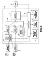
- encoding apparatus a block diagram of illustrative apparatus for encoding digital video data (hereinafter encoding apparatus) in accordance with the present invention is shown.
- the encoding apparatus is shown as comprising a video encoder 1, and audio encoder 2, a multiplexing circuit 3 and a digital storage memory (DSM) 10.
- a digital video signal supplied to a video input terminal is supplied to video encoder 1 which compression encodes (i.e., intraframe and interframe encodes) the video signal in a manner well known in the art and which supplies the encoded video data to a video entry point detection circuit included in multiplexer 3.
- An digital audio signal supplied to an audio input terminal is supplied to audio encoder 2 which encodes the audio data therein in a manner well known in the art to produce packets of audio data and which supplies the packets of audio data to a code buffer 5 included in multiplexer 3.
- video encoder 1 supplies to a controller 8 an entry point ID signal at each output from the video encoder of an I-frame (intracoded frame) of video data.
- Multiplexer 3 is comprised of code buffers 4 and 5, a switching circuit 6, a header appending circuit 7, controller 8, a multiplex system clock generator 9, video entry point detection circuit 31 (hereinafter entry point detector 31), an entry sector generating circuit 32 and an entry point storage memory 33.
- Entry point detector 31 detects the occurrence of an I-frame in the bit stream supplied thereto and supplies to controller 8 another entry point ID signal which indicates the occurrence of an I-frame.
- the entry point ID signals supplied to controller 8 from both video encoder 1 and entry point detector 31 are redundant signals, under certain circumstances, video encoder 1 will not generate the entry point ID signal, for example, as when pre-encoded video data is supplied thereto. Alternatively, video encoder 1 does not supplies the entry point ID signal to control 8. In either case, the occurrence of each I-frame in the bit stream output from entry point detector 31 and which is supplied to code buffer 4 is known.
- Code buffer 4 stores the bit stream data supplied thereto and outputs the stored data to a terminal E1 of switch 6.
- code buffer 5 stores the packets of audio data therein and supplies the stored audio data to a terminal E2 of switch 6.
- Controller 8 functions to control switch 6 to switch between terminals E1 and E2 so as to time-divisionally multiplex packets of video and audio data.
- controller 8 controls entry sector generating circuit 32 to generate entry packet data (to be discussed) and controls switch 6 to switch to terminal E3 so as to effectively insert the generated entry packet data in the bit stream immediately prior to the I-frame.
- System clock generator 9 generates a system clock signal which is supplied to controller 8 which utilizes the supplied signal for purposes of controlling switch 6 to switch between its input terminals E1 - E3.
- Switch 6 supplies the time-divisionally multiplex data to header appending circuit 7 which, in response to a control signal from controller 8, adds a video packet header to the beginning of each packet of video data, adds an audio packet header to the beginning of each packet of audio data, and adds a pack header to each data pack.
- Header appending circuit 7 further appends a back header to each data pack so that each data pack is 2048 bytes long and supplies the resultant signal to digital storage memory DSM which stores the digital data therein.
- Entry point storage memory 33 stores therein position data relating to the detected entry points, that is, positions of selected I-frames output from code buffer 4. Entry point storage memory 33 is further discussed below.
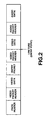
- Fig. 2 illustrates the data structure of a data pack stored in DSM 10.
- the data pack includes a pack header followed by a video packet header, video data, an entry packet, another video packet header, video data, an audio packet header and audio data.
- the pack header includes various information including a pack start code, SCR data, multiplexing rate data, etc.
- the first video packet header and video data immediately following the pack header represent a packet of video data that does not include an I-frame therein since an entry packet has not been inserted-before the first video packet header. However, an entry packet (also called entry data packet herein) precedes the next video packet header and, thus, the ensuing video data includes an I-frame.
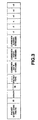
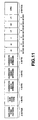
- the data structure of an entry packet is shown in Fig. 3.
- the entry packet includes a packet start code prefix followed by the stream ID data of Oxbf (hexadecimal), length data which identifies the length (i.e., data amount) of the successive packet, "****" ID data (default is FFh) which indicates that the entry packet is specific for a particular person, "****" packet type which indicates the type of classification if the entry packet is specific for a particular person, "current# data streams” data which identifies the number of data sectors that occur before the next entry sector, "current# video streams” data which identifies the number of video sectors that occur before the next entry sector, and "current# audio streams” data which identifies the number of audio sectors that occur before the next entry sector.
- the entry packet further includes "-3", "-2", “-1”, “+1”, “+2” and "+3" entry packet data which identify the locations of 6 different "entry points" corresponding to the beginning positions of 6 different I-frames in the data stream.
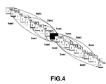
- Fig. 4 a schematic illustration of successive I-frames in the encoded bit stream is shown (the P-frames and B-frames are not shown for convenience) wherein the entry packet stored with (i.e., immediately prior to) each I-frame identifies the locations of 6 different I-frames.
- the "-3", "-2” and "-1" entry packet data identify the beginning locations of 3 I-frames that occur at 3 different predetermined intervals of time prior to the I-frame in which the entry packet is stored.
- the "+1", "+2" and "+3" entry packet data identify the beginning locations of 3 I-frames that occur at the 3 different predetermined intervals of time after the I-frame in which the entry packet is stored. If the 3 different predetermined intervals of time are, for example, 1 second, 2 seconds and 4 seconds, respectively, then the entry packet stored with I-frame 109 identifies the relative locations (relative to I-frame 109) of I-frames 100, 103, 106, 112, 114 and 117, as shown in Fig. 4.
- frame 100 occurs 4 seconds before I-frame 109
- frame 103 occurs 2 seconds before I-frame 109
- frame 106 occurs 1 second before I-frame 109
- I-frame 112 occurs 1 second after I-frame 109
- I-frame 114 occurs 2 seconds after I-frame 109
- I-frame 117 occurs 4 seconds after I-frame 109.
- the entry packet stored with I-frame 110 identify I-frames 108, 105 and 101 which occur 1, 2 and 4 seconds, respectively, before I-frame 110, and also identify I-frames 113, 116 and 119 which occur 1, 2 and 4 seconds, respectively, after I-frame 110.
- Each of the entry packet data "-3", “-2”, ..., "+3" identifies the number of sectors between the current I-frame and the entry point (see Fig. 2) of the respective identified I-frame.
- the predetermined different intervals of time may be different from that shown in Fig. 4.
- the intervals of time 1, 3 and 9 seconds may be used.
- the intervals of time may be varied depending on various properties of the video picture and may vary within the video picture itself. For example, time intervals may be relatively short for a group of images in which the motion therein is large and may be relatively large for a group of images if the motion therein is small.
- an entry sector (i.e., entry packet), which includes the data shown in Fig. 3, is generated by entry sector generator 32 in response to the occurrence of an I-frame (i.e., current I-frame), as previously discussed.
- I-frame i.e., current I-frame
- the entry packet data -3, -2 and -1 can be generated since the positions of I-frames that precede the current frame are known (i.e., they have already occurred in the bit stream).
- Entry point storage memory 33 stores the absolute positions of each entry point (i.e., the beginning of each I-frame) in the bit stream, and entry sector generator 32 is operable to generate relative position data identifying the 3 I-frames that occur before the current frame by using the absolute position of those I-frames stored in memory 33 and the known position of the current frame.
- entry packet data +1, +2 and +3 in entry sector generator 32 and the bit stream including the video and audio data and each of the entry packets (having the dummy data therein) is stored in DSM 10.
- controller 8 At the end of the bit stream (i.e., after all of the video, audio and entry packets are stored in DSM 10), controller 8 ascertains the values of entry packet data +1, +2 and +3 for every one of the entry packets using the positions of each of the entry points (i.e., I-frames) stored in memory 33, and stores the entry packet data +1, +2 and +3 of every entry packet in the appropriate location of DSM 10.
- the digital video data may be variable-bit encoded (e.g., the frame pattern of a GOP is variable).
- an I-frame may not occur at constant intervals in the bit stream and, thus, if a desired interval of time is, for example, 1 second, the encoding apparatus of the present invention cannot assume that the same number of frames (I, P and B-frames) occur between I-frames that are approximately 1 second apart from one another. It is therefore necessary to ensure that each I-frame to which entry packet data of a current frame refers is as closest to the desired time interval as possible.
- Fig. 5 is a flowchart of an operation of controller 8 for identifying the appropriate I-frame to which each entry packet data refers in accordance with the present embodiment. It is noted that controller 8 operates to execute the flowchart of Fig. 5 twice, once when the bit stream is being output from video encoder 1 and subsequently stored in DSM 10 to ascertain the positions of the entry points of I-frames that precede the current frame, and a second time after the bit stream is fully stored in DSM 10 so as to ascertain the positions of the entry points of I-frames that follow each current frame.
- I-frame i.e., current frame
- the position (PCT) of a selected frame that precedes the current frame by 30 frames, which corresponds to a frame that occurs 1 second before the current frame, is ascertained at instruction S101. Since entry points should refer only to I-frames, inquiry S102 determines whether the selected frame is an I-frame. If the selected frame is an I-frame, the beginning position (i.e., the entry point) of the selected frame relative to the current frame is stored as the entry packet data -1 of the entry packet that is stored with (i.e., immediately preceding) the current frame at instruction S104.
- the selected frame is not an I-frame
- the position of a frame that is adjacent to (either before or after) the selected frame in the bit stream is selected as the new selected frame at instruction S103, and then it is determined if the new selected frame is an I-frame at inquiry S102.
- the result of steps of S102 and S103 is a selection of an I-frame that is closest in time to the desired 1 second time interval from the current frame.
- the position (PCT) of a selected second frame that precedes the current frame by 60 frames, which corresponds to a frame that occurs 2 seconds before the current frame, is ascertained at instruction S105. Similar to inquiry S102 and instruction S103, inquiry S106 determines whether the selected second frame is an I-frame, and the position of a frame that is adjacent to the selected second frame in the bit stream is selected as the new selected second frame at instruction S107. When the selected second frame is an I-frame, the beginning position of the selected second frame relative to the current frame is stored as the entry packet data -2 of the entry packet of the current frame at instruction S108.
- Steps 109 through 112 operate in a similar fashion to both sets of steps S101 to S104 and steps S105 to S108, except that an I-frame that precedes the current frame by 120 frames initially is selected, which corresponds to a frame that occurs approximately 4 seconds before the current frame. The beginning position of the selected third frame relative to the current frame then is stored as the entry packet data -3 of the entry packet of the current frame at instruction S112.
- I-frames that occur at times less than 900 milliseconds (ms), 2700 ms and 9000 ms from the current I-frame are not referred to in entry packet data of the current frame.
- next entry point is the first I-picture of a GOP
- the beginning of the GOP is detected by the group start code included in the GOP.
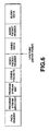
- Fig. 6 illustrates the data structure of the entry sector, that is, a data pack in which an I-frame is included, in accordance with another illustrative embodiment of the present invention.
- the entry sector includes a pack header which includes therein a pack start code, SCR data and MUX rate data.
- the pack header is followed by a program stream directory, a program stream map, a pack other than a video pack, a video packet header, video data including an I-frame, an audio packet header, and audio data.
- the data occurs in a pre-set sequence from the beginning of the sector, thus facilitating data handling.
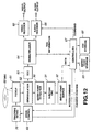
- Fig. 9 is a block diagram of apparatus for encoding digital video data in accordance with another illustrative embodiment of the present invention, wherein a map information storage device 35 is included in multiplexer 3 which receives information from an external entry device (not shown). All elements of the apparatus of Fig. 9, except device 35, are included in the encoding apparatus of Fig. 1 and, therefore, description thereof is omitted herein. Information stored in device 35 is read therefrom and stored as an entry sector each time it constitutes an entry sector. If the information utilizes a future entry sector position, the entry sector position is read from device 33 after the entire bit stream is stored in DSM 10.
- Fig. 10 is a block diagram of illustrative apparatus for decoding digital video data encoded in accordance with the present invention.
- the decoding apparatus of Fig. 10 decodes data stored in DSM 10 having the data structure shown in Fig. 2.
- the decoding apparatus is comprised of a separation device 21, a video decoder 25 and an audio decoder 26.
- the encoded digital data is read from DSM 10 and supplied to a header separation circuit 22 which separates each pack header, each packet header and each entry packet from the read out data and supplies the separated data to controller 24.
- Header separation circuit 22 also supplies the time-divisionally multiplexed data to an input terminal G of a switching circuit 23 which demultiplexes the data (in response to a control signal from controller 24) by supplying video data therein to a terminal H1 and supplying audio data therein to a terminal H2.
- the video data is supplied to video decoder 25 and the audio data is supplied to audio decoder 26 which decode the respective data in manners well known in the art.
- Controller 24 supplies the entry packet data to entry point storage device 24 which stores the supplied data therein.
- DSM 10 supplies to controller 24 readout position information identifying the position in the bit stream of that data supplied to header separation circuit 24.
- a main controller (not shown) supplies appropriate control signals to controller 24, video decoder 25 and audio decoder 26 so that they operate in a particular search mode.
- controller 24 controls DSM 10 to read out the closest I-frame identified by the data stored in device 41, if available. All of the entry points may be pre-stored (e.g., upon power-up) in device 41 (by reproducing the entire bit stream) prior to reproducing in the search mode. As previously discussed, an entry packet is located immediately before each I-frame and, thus, an I-frame is readably obtained.
- DSM 10 reads out the I-frame including the entry packet that is stored immediately therebefore.
- Separation device 21 along with video decoder 25 operate to decode the I-frame and supply the decoded image data at the video output terminal. While the decoding apparatus is in the search mode, the output of audio decoder 26 is muted. While decoding the read out I-frame, controller 24 ascertains the position in DSM 10 of the next I-frame to be read out.
- the entry packet includes therein the positions of 6 different I-frames relative to the position of the currently read out I-frame, and depending on which search mode is selected, the position of one of those 6 different I-frames is ascertained in controller 24.
- Digital data is picked up from an optical disk 60 by pickup device 61 in response to a control signal supplied from a tracking servo device 70.
- a controller 67 supplies a control command to a drive control circuit 69 which produces a drive signal and which supplies the drive signal to tracking servo device 70.
- a data pack is read from the optical disk and supplied to demodulation circuit 62 which demodulates the signal and supplies a demodulated signal to ECC circuit 63 which detects and corrects errors in the supplied signal.
- the signal then is supplied to demultiplexer 64 which supplies video data therein to a video decoder 65, supplies audio data therein to an audio decoder 66 and supplies TOC information to controller 67.
- TOC information generally is stored in the first reproduced sector.
- Controller 67 supplies the TOC information to TOC storage device 68 which stores the TOC information therein. Further, controller 67 causes a display (not shown) to indicate to a user that the TOC data is loaded.
- drive controller 69 drives via tracking servo circuit 70 the pickup device 61 to reproduce data from disk 60 at a position indicated by the user.
- controller 67 controls video decoder 65 and audio decoder 66 to prepare for decoding.
- demodulation circuit 62 supplies the demodulated reproduced data to an entry point detection circuit 90 which extracts entry point data (e.g., an entry packet) therefrom and supplies the extracted data to subcode CRC circuit 91 which corrects errors therein.
- entry point data e.g., an entry packet
- subcode CRC circuit 91 which corrects errors therein.
- the positions of the entry points of the I-frames identified in the entry point data are stored in entry point buffer 92.
- Controller 67 reads out the data of the next entry point from the entry point buffer 92 and supplies the read-out information to an entry point storage device 93 which stores the data therein. Controller 92 is supplied with the information on the current read-out position from drive controller 69 and, thus, the position and contents of the next entry points can be associatively stored in device 93.
- the entry point portions are separated from the data by entry point detection circuit 90 and stored in the entry point buffer 92 for retrieval by controller 67.
- the ensuing video data is an I-frame which is quickly decoded and output.
- the entry packet includes therein the positions of 6 different I-frames relative to the position of the currently read out frame, and depending on the search mode, the position of one of the 6 I-frames is ascertained in controller 24. This operation is similar to that described above with reference to Fig. 10.
Claims (23)
- Gerät zum Codieren eines digitalen Videosignals, welches umfaßt:dadurch gekennzeichnet, daß die Eintrittsstellen-Identifikationseinrichtung (31, 32, 8, 6) so arbeitet, daß die Positionsdaten jedes hinzugefügten Eintrittsstellenpakets die Positionen innerhalb der codierten Daten in bezug auf den verknüpften intrarahmen-codierten Rahmen mehrer anderer intrarahmen-codierter Rahmen, die von dem verknüpften intrarahmen-codierten Rahmen beabstandet sind, jenseits derjenigen drei intrarahmen-codierte Rahmen identifizieren, die dem verknüpften intrarahmen-codierten Rahmen am nächsten sind, so daß sie bei entsprechend vorher-festgelegten Zeitintervallen vom verknüpften intrarahmen-codierten Rahmen in einem Videobild auftreten, welches durch das digitale Videosignal dargestellt wird.eine Codiereinrichtung (1), um das digitale Videosignal mit einer variablen Rate zu codieren, um variabel-raten-codierte Videodaten zu erzeugen, die sowohl intrarahmen- als auch interrahmen-codierte Rahmen umfassen;eine Eintrittsstellen-Identifikationseinrichtung (31, 32, 8, 6), die auf das Vorhandensein von intrarahmen-codierten Rahmen in den codierten Videodaten anspricht, um codierte Daten zu erzeugen und um zu diesen in Zusammenhang mit den intrarahmen-codierten Rahmen Eintrittsstellenpakete hinzuzufügen, die das Vorhandensein der intrarahmen-codierten Rahmen zeigen, wobei jedes Eintrittsstellenpaket Positionsdaten umfaßt, die die Positionen innerhalb der codierten Daten in bezug auf den verknüpften intrarahmen-codierten Rahmen anderer intrarahmen-codierter Rahmen identifizieren; undeine Aufzeichnungseinrichtung, um die codierten Videodaten, denen die erzeugten Eintrittstellenpakete hinzugefügt sind, auf einem Aufzeichnungsträger (10) aufzuzeichnen;
- Gerät nach Anspruch 1, wobei die Eintrittsstellen-Identifikationseinrichtung (31, 32, 8, 6) so arbeitet, daß die Positionsdaten die Position eines intrarahmen-codierten Rahmens identifizieren, der in den codierten Videodaten zeitlich am nächsten zu einem Rahmen liegt, der in einem der vorher-festgelegten Zeitintervalle im Videobild auftritt, wenn der Rahmen, der bei dem vorher-festgelegten Zeitintervall auftritt, kein intrarahmen-codierter Rahmen ist.
- Gerät nach Anspruch 2, wobei die Eintrittsstellen-Identifikationseinrichtung (31, 32, 8, 6) die jeweiligen Eintrittstellenpakete jedem der intrarahmen-codierten Rahmen hinzufügt.
- Gerät nach Anspruch 3, wobei die Eintrittstellen-Identifikationseinrichtung (31, 32, 8, 6) das Eintrittsstellenpaket dem Anfang jeder der intrarahmen-codierten Rahmen hinzufügt.
- Gerät nach einem der Ansprüche 1 bis 4, wobei die mehreren intrarahmen-codierten Rahmen einen intrarahmen-codierte Rahmen umfassen, der vorhergeht, und einen intrarahmen-codierten Rahmen, der dem intrarahmen-codierten Rahmen-folgt, der mit dem jeweiligen Eintrittstellenpaket verknüpft ist.
- Gerät nach einem der Ansprüche 1 bis 4, wobei die mehreren intrarahmen-codierten Rahmen intrarahmen-codierte Rahmen umfassen, die bei den jeweiligen vorher-festgelegten Zeitintervallen nach dem intrarahmen-codierten Rahmen auftreten, der mit dem jeweiligen Eintrittsstellenpaket verknüpft ist.
- Gerät nach Anspruch 6, wobei die mehreren intrarahmen-codierten Rahmen auβerdem intrarahmen-codierte Rahmen umfassen, die bei den jeweiligen vorher-festgelegten Zeitintervallen vor dem intrarahmen-codierten Rahmen, der mit dem jeweiligen Eintrittsstellenpaket verknüpft ist, auftreten.
- Gerät nach einem der Ansprüche 1 bis 7, wobei die jeweiligen vorher-festgelegten Zeitintervalle 1, 2 und 4 Sekunden sind.
- Gerät nach einem der Ansprüche 1 bis 7, wobei die entsprechenden vorher-festgelegten Zeitintervalle 1, 3 und 9 Sekunden sind.
- Verfahren zum Codieren eines digitalen Videosignals, welches umfaßt:
Codieren (1), mit einer variablen Rate, des digitalen Videosignals, um variabel-raten-codierte Videodaten zu erzeugen, die sowohl intrarahmen- als auch interrahmen-codierte Rahmen umfassen:dadurch gekennzeichnet, daß die Positionsdaten jedes hinzugefügten Eintrittsstellenpakets die Position innerhalb der codierten Daten in bezug auf den verknüpften intrarahmen-codierten Rahmen mehrerer anderer intrarahmen-codierter Rahmen, die von dem verknüpften intrarahmen-codierten Rahmen beabstandet sind, jenseits derjenigen drei intrarahmen-codierten Rahmen identifizieren, die dem verknüpften intrarahmen-codierten Rahmen am nächsten sind, so daß sie bei entsprechenden vorher-festgelegten Zeitintervallen vom verknüpften intrarahmen-codierten Rahmen in einem Videobild, welches durch das digitale Videosignal dargestellt wird, auftreten.als Antwort auf das Vorhandensein in den codierten Videodaten der intrarahmen-codierten Rahmen Erzeugen und Hinzufügen - zu den codierten Daten in Zusammenhang mit den intrarahmen-codierten Rahmen - von Eintrittsstellenpaketen, die das Vorhandensein der intrarahmen-codierten Rahmen zeigen, wobei jedes Eintrittsstellenpaket Positionsdaten umfaßt, die Positionen innerhalb der codierten Daten in bezug auf den verknüpften intrarahmen-codierten Rahmen anderer intrarahmen-codierter Rahmen identifizieren; undAufzeichnen der codierten Videodaten, denen die erzeugten Eintrittsstellenpakete hinzugefügt wurden, auf einem Aufzeichnungsträger (10); - Verfahren nach Anspruch 10, wobei die Positionsdaten die Position eines intrarahmen-codierten Rahmens identifizieren, der in den codierten Videodaten zeitlich am nächsten einem Rahmen ist, der bei einem der vorher-festgelegten Zeitintervalle im Videobild auftritt, wenn der Rahmen, der in dem vorher-festgelegten Zeitintervall auftritt, kein intrarahmen-codierter Rahmen ist.
- Verfahren nach Anspruch 10 oder 11, wobei die entsprechenden Eintrittsstellenpakete jedem der intrarahmen-codierten Rahmen hinzugefügt sind.
- Verfahren nach Anspruch 12, wobei das Eintrittsstellenpaket dem Anfang eines jeden der intrarahmen-codierten Rahmen hinzugefügt ist.
- Verfahren nach einem der Ansprüche 10 bis 14, wobei die mehreren intrarahmen-codierten Rahmen einen intrarahmen-codierten Rahmen umfassen, der vorhergeht, und einen intrarahmen-codierten Rahmen, der auf den intrarahmen-codierten Rahmen folgt, der mit dem jeweiligen Eintrittsstellenpaket verknüpft ist.
- Verfahren nach einem der Ansprüche 10 bis 14, wobei die mehreren intrarahmen-codierten Rahmen intrarahmen-codierte Rahmen umfassen, die bei den entsprechenden vorher-festgelegten Zeitintervallen nach dem intrarahmen-codierten Rahmen auftreten, der mit dem jeweiligen Eintrittstellenpaket verknüpft ist.
- Verfahren nach Anspruch 15, wobei die mehreren intrarahmen-codierten Rahmen außerdem intrarahmen-codierte Rahmen umfassen, die bei den entsprechenden vorher-festgelegten Zeitintervallen vor dem intrarahmen-codierten Rahmen auftreten, der mit dem jeweiligen Eintrittsstellenpaket verknüpft ist.
- Verfahren nach einem der Ansprüche 10 bis 16, wobei die jeweiligen vorher-festgelegten Zeitintervalle 1, 2 und 4 Sekunden sind.
- Verfahren nach einem der Ansprüche 10 bis 16, wobei die entsprechenden vorher-festgelegten Zeitintervalle 1, 3 und 9 Sekunden sind.
- Aufzeichnungsträger, der umfaßt:dadurch gekennzeichnet, daß die Positionsdaten eines jeden Eintrittsstellen-Datenpakets die Positionen innerhalb der gespeicherten codierten Daten in bezug auf den verknüpften intrarahmen-codierten Rahmen mehrerer anderer intrarahmen-codierter Rahmen, die vom verknüpften intra-rahmen-codierten Rahmen beabstandet sind, jenseits derjenigen drei intrarahmen-codierten Rahmen identifizieren, die dem verknüpften intrarahmen-codierten Rahmen am nächsten sind, so daß sie bei entsprechenden vorher-festgelegten Zeitintervallen vom verknüpften intrarahmen-codierten Rahmen in einem Videobild, welches durch das digitale Videosignal dargestellt wird, auftreten.mehrere Variabel-Längen-Videodatenbereiche, in denen digitale Videodaten, die mit einer variablen Rate codiert sind, gespeichert sind, wobei die codierten digitalen Videodaten mehrere intrarahmen- und interrahmen-codierte Rahmen umfassen, von denen jeder in entsprechend einem der Videodatenbereiche gespeichert ist; undmehrere Eintrittstellen-Datenpaketbereiche, in denen Eintrittsstellen-Datenpakete gespeichert sind, wobei die Eintrittsstellen-Datenpakete das Vorhandensein von Videodatenbereichen zeigen, in denen die verknüpften intrarahmen-codierten Rahmen gespeichert sind, wobei jedes Eintrittsstellen-Datenpaket Positionsdaten umfaßt, die die Positionen innerhalb der gespeicherten codierten Daten in bezug auf den verknüpften intrarahmen-codierten Rahmen der anderen Videodatenbereiche identifizieren, in welchen intrarahmen-codierte Rahmen gespeichert sind;
- Aufzeichnungsträger nach Anspruch 19, wobei ein entsprechender einer der Eintrittstellen-Datenpaketbereiche unmittelbar auf dem Aufzeichnungsträger jedem der Videodatenbereiche vorhergeht, in welchem intrarahmen-codierte Rahmen gespeichert sind.
- Aufzeichnungsträger nach Anspruch 20, wobei die mehreren anderen intrarahmen-codierter Rahmen einen intrarahmen-codierten Rahmen, der vorhergeht, und einen intrarahmen-codierten Rahmen umfassen, der dem Videodatenbereich folgt, der unmittelbar dem Eintrittsstellen-Paketbereich folgt, in welchem das entsprechende Eintrittsstellen-Datenpaket gespeichert ist.
- Aufzeichnungsträger nach Anspruch 19, 20 oder 21, wobei die mehreren intra-rahmen-codierten Rahmen intrarahmen-codierte Rahmen umfassen, die bei den entsprechenden vorher-festgelegten Zeitintervallen nach dem intrarahmen-codierten Rahmen im Videodatenbereich auftreten, der unmittelbar dem Eintrittsstellen-Datenpaketbereich folgt, in welchem das entsprechende Eintrittsstellen-Datenpaket gespeichert ist.
- Aufzeichnungsträger nach Anspruch 19, 20 oder 21, wobei die mehreren intra-rahmen-codierten Rahmen außerdem intrarahmen-codierte Rahmen umfassen, die bei den entsprechenden vorher-festgelegten Zeitintervallen vor dem intrarahmen-codierten Rahmen im Videodatenbereich auftreten, der unmittelbar dem Eintrittsstellen-Datenpaketbereich folgt, in welchem das jeweilige Eintrittsstellen-Datenpaket gespeichert ist.
Priority Applications (1)
| Application Number | Priority Date | Filing Date | Title |
|---|---|---|---|
| EP20000202503 EP1039756B1 (de) | 1995-08-02 | 1996-07-30 | Gerät und Verfahren zur Kodierung von digitalen Videodaten |
Applications Claiming Priority (3)
| Application Number | Priority Date | Filing Date | Title |
|---|---|---|---|
| JP197813/95 | 1995-08-02 | ||
| JP19781395 | 1995-08-02 | ||
| JP19781395A JP3484832B2 (ja) | 1995-08-02 | 1995-08-02 | 記録装置、記録方法、再生装置及び再生方法 |
Related Child Applications (1)
| Application Number | Title | Priority Date | Filing Date |
|---|---|---|---|
| EP20000202503 Division EP1039756B1 (de) | 1995-08-02 | 1996-07-30 | Gerät und Verfahren zur Kodierung von digitalen Videodaten |
Publications (3)
| Publication Number | Publication Date |
|---|---|
| EP0757492A2 EP0757492A2 (de) | 1997-02-05 |
| EP0757492A3 EP0757492A3 (de) | 1997-11-19 |
| EP0757492B1 true EP0757492B1 (de) | 2001-09-12 |
Family
ID=16380777
Family Applications (2)
| Application Number | Title | Priority Date | Filing Date |
|---|---|---|---|
| EP20000202503 Expired - Lifetime EP1039756B1 (de) | 1995-08-02 | 1996-07-30 | Gerät und Verfahren zur Kodierung von digitalen Videodaten |
| EP19960305566 Expired - Lifetime EP0757492B1 (de) | 1995-08-02 | 1996-07-30 | Gerät und Verfahren zur Kodierung von digitalen Videodaten |
Family Applications Before (1)
| Application Number | Title | Priority Date | Filing Date |
|---|---|---|---|
| EP20000202503 Expired - Lifetime EP1039756B1 (de) | 1995-08-02 | 1996-07-30 | Gerät und Verfahren zur Kodierung von digitalen Videodaten |
Country Status (13)
| Country | Link |
|---|---|
| US (1) | US6363212B1 (de) |
| EP (2) | EP1039756B1 (de) |
| JP (1) | JP3484832B2 (de) |
| KR (1) | KR100440649B1 (de) |
| CN (1) | CN1130922C (de) |
| AT (2) | ATE249710T1 (de) |
| AU (1) | AU723796B2 (de) |
| CA (1) | CA2181863C (de) |
| DE (2) | DE69615111T2 (de) |
| ES (2) | ES2161331T3 (de) |
| MX (2) | MX9603108A (de) |
| MY (1) | MY117793A (de) |
| TW (1) | TW317064B (de) |
Families Citing this family (61)
| Publication number | Priority date | Publication date | Assignee | Title |
|---|---|---|---|---|
| KR100223163B1 (ko) * | 1995-12-11 | 1999-10-15 | 윤종용 | 배속재생을 위한 디스크포맷 및 이를 이용한 동화상데이타의 배속재생방법 및 그장치 |
| JP2001509354A (ja) * | 1997-01-21 | 2001-07-10 | サーノフ コーポレイション | 接続点の存在を示す情報ストリームシンタックス |
| EP2387038A3 (de) * | 1997-10-17 | 2012-01-11 | Sony Corporation | Verarbeitungsvorrichtung und -verfahren zur Aufzeichnung, Verarbeitungvorrichtung und -verfahren zur Wiedergabe, Programm zur Steuerung einer Aufzeichnungsvorrichtung, Programm zur Steuerung einer Wiedergabevorrichtung, Aufzeichnungsmedium |
| KR100324512B1 (ko) * | 1998-07-14 | 2002-06-26 | 구자홍 | 실시간데이터기록및재생장치와그제어방법 |
| US8577205B2 (en) * | 1998-07-30 | 2013-11-05 | Tivo Inc. | Digital video recording system |
| US7558472B2 (en) | 2000-08-22 | 2009-07-07 | Tivo Inc. | Multimedia signal processing system |
| US6233389B1 (en) | 1998-07-30 | 2001-05-15 | Tivo, Inc. | Multimedia time warping system |
| US8380041B2 (en) * | 1998-07-30 | 2013-02-19 | Tivo Inc. | Transportable digital video recorder system |
| US6647202B1 (en) * | 1998-07-30 | 2003-11-11 | Matsushita Electric Industrial Co., Ltd. | Video signal reproducing apparatus capable of reproducing bitstreams and video signal reproducing method |
| WO2001022729A1 (en) | 1999-09-20 | 2001-03-29 | Tivo, Inc. | Closed caption tagging system |
| US7106946B1 (en) * | 1999-09-28 | 2006-09-12 | Sony Corporation | Transport stream processing device, and associated methodology of generating and aligning source data packets in a physical data structure |
| JP4389365B2 (ja) * | 1999-09-29 | 2009-12-24 | ソニー株式会社 | トランスポートストリーム記録装置および方法、トランスポートストリーム再生装置および方法、並びにプログラム記録媒体 |
| US7340153B2 (en) * | 2000-01-11 | 2008-03-04 | Hitachi, Ltd. | Apparatus and method for recording and reproducing information |
| CN1367612A (zh) * | 2000-06-30 | 2002-09-04 | 株式会社东芝 | 特殊再生控制信息记录方法,产生装置及方法,图象再生装置 |
| GB0031221D0 (en) * | 2000-12-21 | 2001-01-31 | Koninkl Philips Electronics Nv | Compressed-data processing arrangement and related method |
| US8081865B2 (en) * | 2001-03-29 | 2011-12-20 | Panasonic Corporation | AV data recording apparatus and method, recording media recorded by the same, AV data reproducing apparatus and method, and AV data recording and reproducing apparatus and method |
| US20070230921A1 (en) * | 2001-04-05 | 2007-10-04 | Barton James M | Multimedia time warping system |
| US8238725B2 (en) * | 2001-08-20 | 2012-08-07 | Broadcom Corporation | System and method for providing personal video recording trick modes |
| US20030039471A1 (en) * | 2001-08-21 | 2003-02-27 | Hashimoto Roy T. | Switching compressed video streams |
| US20030093800A1 (en) * | 2001-09-12 | 2003-05-15 | Jason Demas | Command packets for personal video recorder |
| US8923688B2 (en) * | 2001-09-12 | 2014-12-30 | Broadcom Corporation | Performing personal video recording (PVR) functions on digital video streams |
| JP3584913B2 (ja) * | 2001-09-21 | 2004-11-04 | ソニー株式会社 | データ出力方法、記録方法および装置、再生方法および装置、データ送信方法および受信方法 |
| CN101494791B (zh) * | 2001-10-17 | 2010-12-29 | 松下电器产业株式会社 | 动态图像解码方法及装置 |
| US8285111B2 (en) * | 2002-04-19 | 2012-10-09 | Tivo Inc. | Method and apparatus for creating an enhanced photo digital video disc |
| US7200321B2 (en) * | 2002-04-19 | 2007-04-03 | Tivo Inc. | Method and apparatus for creating an expanded functionality digital video disc |
| CN100592417C (zh) | 2002-04-25 | 2010-02-24 | 皇家飞利浦电子股份有限公司 | 定义数据流中的入口点的方法和设备 |
| US8000584B1 (en) * | 2002-04-26 | 2011-08-16 | Tivo Inc. | Approach for storing digital content onto digital versatile discs (DVDs) |
| KR20040095034A (ko) * | 2003-05-06 | 2004-11-12 | 삼성전자주식회사 | 엔트리 포인트 결정 방법 및 그 장치 |
| JP4228288B2 (ja) * | 2003-06-11 | 2009-02-25 | ソニー株式会社 | 記録制御装置および方法、プログラム、並びにデータ記録方法 |
| TWI478154B (zh) * | 2003-10-04 | 2015-03-21 | Samsung Electronics Co Ltd | 儲存搜尋資訊的再生方法 |
| WO2005053316A1 (ja) * | 2003-11-26 | 2005-06-09 | Sanyo Electric Co.,Ltd. | 無線映像送信装置、無線映像受信装置及び無線映像送受信システム並びに信号生成装置、信号復号装置及び信号生成復号装置 |
| CN100481923C (zh) * | 2004-01-30 | 2009-04-22 | 松下电器产业株式会社 | 内容再现装置和内容段获得方法 |
| JP4608953B2 (ja) * | 2004-06-07 | 2011-01-12 | ソニー株式会社 | データ記録装置、方法およびプログラム、データ再生装置、方法およびプログラム、ならびに、記録媒体 |
| JP4088274B2 (ja) * | 2004-06-28 | 2008-05-21 | 株式会社東芝 | メタデータの構造及びその編集方法 |
| CA2588630C (en) | 2004-11-19 | 2013-08-20 | Tivo Inc. | Method and apparatus for secure transfer of previously broadcasted content |
| US8214220B2 (en) | 2005-05-26 | 2012-07-03 | Lg Electronics Inc. | Method and apparatus for embedding spatial information and reproducing embedded signal for an audio signal |
| JP2009500657A (ja) | 2005-06-30 | 2009-01-08 | エルジー エレクトロニクス インコーポレイティド | オーディオ信号をエンコーディング及びデコーディングするための装置とその方法 |
| EP1946294A2 (de) | 2005-06-30 | 2008-07-23 | LG Electronics Inc. | Vorrichtung zum codieren und decodieren von audiosignalen und verfahren dafür |
| WO2007004833A2 (en) | 2005-06-30 | 2007-01-11 | Lg Electronics Inc. | Method and apparatus for encoding and decoding an audio signal |
| US7765104B2 (en) | 2005-08-30 | 2010-07-27 | Lg Electronics Inc. | Slot position coding of residual signals of spatial audio coding application |
| US8577483B2 (en) | 2005-08-30 | 2013-11-05 | Lg Electronics, Inc. | Method for decoding an audio signal |
| KR20080049735A (ko) | 2005-08-30 | 2008-06-04 | 엘지전자 주식회사 | 오디오 신호의 디코딩 방법 및 장치 |
| US7788107B2 (en) | 2005-08-30 | 2010-08-31 | Lg Electronics Inc. | Method for decoding an audio signal |
| US7696907B2 (en) | 2005-10-05 | 2010-04-13 | Lg Electronics Inc. | Method and apparatus for signal processing and encoding and decoding method, and apparatus therefor |
| US7751485B2 (en) | 2005-10-05 | 2010-07-06 | Lg Electronics Inc. | Signal processing using pilot based coding |
| US7646319B2 (en) | 2005-10-05 | 2010-01-12 | Lg Electronics Inc. | Method and apparatus for signal processing and encoding and decoding method, and apparatus therefor |
| US7672379B2 (en) | 2005-10-05 | 2010-03-02 | Lg Electronics Inc. | Audio signal processing, encoding, and decoding |
| WO2007040365A1 (en) | 2005-10-05 | 2007-04-12 | Lg Electronics Inc. | Method and apparatus for signal processing and encoding and decoding method, and apparatus therefor |
| KR100857120B1 (ko) | 2005-10-05 | 2008-09-05 | 엘지전자 주식회사 | 신호 처리 방법 및 이의 장치, 그리고 인코딩 및 디코딩방법 및 이의 장치 |
| US7716043B2 (en) | 2005-10-24 | 2010-05-11 | Lg Electronics Inc. | Removing time delays in signal paths |
| US7752053B2 (en) | 2006-01-13 | 2010-07-06 | Lg Electronics Inc. | Audio signal processing using pilot based coding |
| KR100820965B1 (ko) * | 2006-02-24 | 2008-04-10 | 엘지전자 주식회사 | 무선 디지털티브이에서의 비디오와 오디오 신호 동기화시스템 |
| US8279928B2 (en) * | 2006-05-09 | 2012-10-02 | Canon Kabushiki Kaisha | Image encoding apparatus and encoding method, image decoding apparatus and decoding method |
| JP4284370B2 (ja) * | 2007-03-09 | 2009-06-24 | 株式会社東芝 | ビデオサーバ及びビデオ編集システム |
| CN101321265B (zh) * | 2007-06-07 | 2011-03-16 | 中兴通讯股份有限公司 | 对等网络媒体点播跨帧播放方式的实现方法及系统 |
| FR2923645B1 (fr) * | 2007-11-09 | 2010-01-08 | Thierry Prigent | Procede d'enregistrement de donnees pour la lecture a long terme de ces donnees |
| JP4886823B2 (ja) * | 2009-07-23 | 2012-02-29 | 株式会社東芝 | 記録再生装置、ビデオサーバ及び記録再生装置の電源制御方法 |
| US20110123173A1 (en) * | 2009-11-24 | 2011-05-26 | Verizon Patent And Licensing Inc. | Trick play advertising systems and methods |
| RU2652091C2 (ru) * | 2013-06-21 | 2018-04-25 | Сони Корпорейшн | Устройство и способ передачи, устройство воспроизведения, способ воспроизведения и устройство приема |
| KR102225254B1 (ko) * | 2014-08-27 | 2021-03-09 | 삼성전자주식회사 | 표시 패널 컨트롤러 및 이를 포함하는 표시 장치 |
| CN113132807B (zh) * | 2019-12-30 | 2023-04-07 | 成都鼎桥通信技术有限公司 | 基于视频的关键帧请求方法、装置、设备及存储介质 |
Family Cites Families (8)
| Publication number | Priority date | Publication date | Assignee | Title |
|---|---|---|---|---|
| JP2797404B2 (ja) * | 1989-04-20 | 1998-09-17 | ソニー株式会社 | 動画像データの記録方式 |
| US5122886A (en) * | 1989-06-19 | 1992-06-16 | Pioneer Electronic Corporation | Selective information playback from recording medium based on user input content codes |
| JP2712656B2 (ja) * | 1989-10-25 | 1998-02-16 | 日本電気ホームエレクトロニクス株式会社 | Cd―rom記録方法 |
| DE69330358T2 (de) * | 1992-09-22 | 2002-02-28 | Sony Corp | Gerät und Verfahren zur Verarbeitung von digitalen Videosignalen |
| JP3551447B2 (ja) * | 1992-09-22 | 2004-08-04 | ソニー株式会社 | データ符号化装置および方法、データ復号化装置および方法 |
| JP3240017B2 (ja) * | 1993-01-11 | 2001-12-17 | ソニー株式会社 | Mpeg信号記録方法およびmpeg信号再生方法 |
| KR100330293B1 (ko) * | 1993-09-21 | 2002-03-27 | 이데이 노부유끼 | 데이타 전송 방법 및 장치, 데이타 복호화 장치, 및데이타 기록 매체 |
| EP0651391A3 (de) * | 1993-10-29 | 1997-02-05 | Tokyo Shibaura Electric Co | Gewindebefestigung. |
-
1995
- 1995-08-02 JP JP19781395A patent/JP3484832B2/ja not_active Expired - Lifetime
-
1996
- 1996-07-23 CA CA 2181863 patent/CA2181863C/en not_active Expired - Fee Related
- 1996-07-30 ES ES96305566T patent/ES2161331T3/es not_active Expired - Lifetime
- 1996-07-30 AT AT00202503T patent/ATE249710T1/de active
- 1996-07-30 ES ES00202503T patent/ES2201999T3/es not_active Expired - Lifetime
- 1996-07-30 EP EP20000202503 patent/EP1039756B1/de not_active Expired - Lifetime
- 1996-07-30 EP EP19960305566 patent/EP0757492B1/de not_active Expired - Lifetime
- 1996-07-30 DE DE1996615111 patent/DE69615111T2/de not_active Expired - Lifetime
- 1996-07-30 AT AT96305566T patent/ATE205656T1/de active
- 1996-07-30 DE DE1996629957 patent/DE69629957T2/de not_active Expired - Lifetime
- 1996-07-31 KR KR1019960031678A patent/KR100440649B1/ko not_active IP Right Cessation
- 1996-07-31 MY MYPI9603138 patent/MY117793A/en unknown
- 1996-07-31 MX MX9603108A patent/MX9603108A/es unknown
- 1996-08-01 AU AU60868/96A patent/AU723796B2/en not_active Ceased
- 1996-08-02 CN CN96112178A patent/CN1130922C/zh not_active Expired - Fee Related
- 1996-08-05 TW TW85109442A patent/TW317064B/zh not_active IP Right Cessation
-
1999
- 1999-07-29 US US09/363,723 patent/US6363212B1/en not_active Expired - Lifetime
-
2000
- 2000-12-14 MX MXPA00012448A patent/MXPA00012448A/es active IP Right Grant
Also Published As
| Publication number | Publication date |
|---|---|
| AU723796B2 (en) | 2000-09-07 |
| CA2181863A1 (en) | 1997-02-03 |
| CN1130922C (zh) | 2003-12-10 |
| EP1039756B1 (de) | 2003-09-10 |
| ES2161331T3 (es) | 2001-12-01 |
| EP0757492A2 (de) | 1997-02-05 |
| DE69629957D1 (de) | 2003-10-16 |
| TW317064B (de) | 1997-10-01 |
| JPH0951533A (ja) | 1997-02-18 |
| MY117793A (en) | 2004-08-30 |
| KR100440649B1 (ko) | 2005-04-06 |
| KR970014296A (ko) | 1997-03-29 |
| DE69615111T2 (de) | 2002-06-13 |
| EP1039756A3 (de) | 2001-01-31 |
| US6363212B1 (en) | 2002-03-26 |
| ATE249710T1 (de) | 2003-09-15 |
| EP0757492A3 (de) | 1997-11-19 |
| EP1039756A2 (de) | 2000-09-27 |
| ATE205656T1 (de) | 2001-09-15 |
| JP3484832B2 (ja) | 2004-01-06 |
| CA2181863C (en) | 2006-01-24 |
| CN1152243A (zh) | 1997-06-18 |
| AU6086896A (en) | 1997-02-06 |
| DE69629957T2 (de) | 2004-07-15 |
| DE69615111D1 (de) | 2001-10-18 |
| MXPA00012448A (es) | 2005-07-25 |
| ES2201999T3 (es) | 2004-04-01 |
| MX9603108A (es) | 1997-06-28 |
Similar Documents
| Publication | Publication Date | Title |
|---|---|---|
| EP0757492B1 (de) | Gerät und Verfahren zur Kodierung von digitalen Videodaten | |
| US5504585A (en) | Apparatus and method for providing plural pictures while searching a recording medium whereon a compressed picture signal is recorded | |
| US5737479A (en) | Apparatus and method for inserting rating code into the digital video signal | |
| US5568274A (en) | Apparatus and method for processing a variable-rate coded signal for erecording to provide a high-speed search capability, apparatus and method for reproducing such processed signal, and recording including such processed signal | |
| EP0794667B1 (de) | Gerät und Verfahren zur Verarbeitung von digitalen Videosignalen | |
| KR100405249B1 (ko) | 디코딩및리버스재생장치및방법 | |
| AU714628B2 (en) | Information carrier, device for reading and device for providing the information carrier and method of transmitting picture information | |
| KR100330293B1 (ko) | 데이타 전송 방법 및 장치, 데이타 복호화 장치, 및데이타 기록 매체 | |
| JP3551447B2 (ja) | データ符号化装置および方法、データ復号化装置および方法 | |
| JP3695425B2 (ja) | 再生装置 | |
| EP0815558B1 (de) | Aufzeichnung von einem datenreduzierten digitalen videosignal in schrägen spuren auf einem aufzeichnungsträger | |
| JP3695424B2 (ja) | 再生装置 | |
| JP3589241B2 (ja) | データ符号化装置および方法、データ復号化装置および方法 | |
| JP3582530B2 (ja) | 記録装置および方法、再生装置および方法 | |
| JP3695423B2 (ja) | 再生装置 | |
| JP3651479B2 (ja) | 記録媒体へのビデオデータの記録方法、ビデオデータを記録した記録媒体の生産方法 | |
| JP3582529B2 (ja) | データ符号化装置および方法、データ復号化装置および方法 | |
| JP4191207B2 (ja) | 記録媒体 | |
| JP2004304844A (ja) | データ符号化方法、ビデオデータを記録した記録媒体の生産方法、並びに記録媒体 |
Legal Events
| Date | Code | Title | Description |
|---|---|---|---|
| PUAI | Public reference made under article 153(3) epc to a published international application that has entered the european phase |
Free format text: ORIGINAL CODE: 0009012 |
|
| AK | Designated contracting states |
Kind code of ref document: A2 Designated state(s): AT DE ES FR GB IT NL |
|
| PUAL | Search report despatched |
Free format text: ORIGINAL CODE: 0009013 |
|
| AK | Designated contracting states |
Kind code of ref document: A3 Designated state(s): AT DE ES FR GB IT NL |
|
| 17P | Request for examination filed |
Effective date: 19980415 |
|
| 17Q | First examination report despatched |
Effective date: 20000105 |
|
| GRAG | Despatch of communication of intention to grant |
Free format text: ORIGINAL CODE: EPIDOS AGRA |
|
| RTI1 | Title (correction) |
Free format text: APPARATUS AND METHOD FOR ENCODING DIGITAL VIDEO DATA |
|
| GRAG | Despatch of communication of intention to grant |
Free format text: ORIGINAL CODE: EPIDOS AGRA |
|
| GRAH | Despatch of communication of intention to grant a patent |
Free format text: ORIGINAL CODE: EPIDOS IGRA |
|
| GRAH | Despatch of communication of intention to grant a patent |
Free format text: ORIGINAL CODE: EPIDOS IGRA |
|
| GRAA | (expected) grant |
Free format text: ORIGINAL CODE: 0009210 |
|
| AK | Designated contracting states |
Kind code of ref document: B1 Designated state(s): AT DE ES FR GB IT NL |
|
| REF | Corresponds to: |
Ref document number: 205656 Country of ref document: AT Date of ref document: 20010915 Kind code of ref document: T |
|
| REF | Corresponds to: |
Ref document number: 69615111 Country of ref document: DE Date of ref document: 20011018 |
|
| REG | Reference to a national code |
Ref country code: ES Ref legal event code: FG2A Ref document number: 2161331 Country of ref document: ES Kind code of ref document: T3 |
|
| REG | Reference to a national code |
Ref country code: GB Ref legal event code: IF02 |
|
| ET | Fr: translation filed | ||
| PLBE | No opposition filed within time limit |
Free format text: ORIGINAL CODE: 0009261 |
|
| STAA | Information on the status of an ep patent application or granted ep patent |
Free format text: STATUS: NO OPPOSITION FILED WITHIN TIME LIMIT |
|
| 26N | No opposition filed | ||
| PGFP | Annual fee paid to national office [announced via postgrant information from national office to epo] |
Ref country code: NL Payment date: 20140721 Year of fee payment: 19 Ref country code: DE Payment date: 20140721 Year of fee payment: 19 |
|
| PGFP | Annual fee paid to national office [announced via postgrant information from national office to epo] |
Ref country code: AT Payment date: 20140611 Year of fee payment: 19 Ref country code: GB Payment date: 20140721 Year of fee payment: 19 Ref country code: FR Payment date: 20140721 Year of fee payment: 19 Ref country code: ES Payment date: 20140728 Year of fee payment: 19 |
|
| PGFP | Annual fee paid to national office [announced via postgrant information from national office to epo] |
Ref country code: IT Payment date: 20140729 Year of fee payment: 19 |
|
| REG | Reference to a national code |
Ref country code: DE Ref legal event code: R119 Ref document number: 69615111 Country of ref document: DE |
|
| REG | Reference to a national code |
Ref country code: AT Ref legal event code: MM01 Ref document number: 205656 Country of ref document: AT Kind code of ref document: T Effective date: 20150730 |
|
| GBPC | Gb: european patent ceased through non-payment of renewal fee |
Effective date: 20150730 |
|
| REG | Reference to a national code |
Ref country code: NL Ref legal event code: MM Effective date: 20150801 |
|
| PG25 | Lapsed in a contracting state [announced via postgrant information from national office to epo] |
Ref country code: DE Free format text: LAPSE BECAUSE OF NON-PAYMENT OF DUE FEES Effective date: 20160202 Ref country code: GB Free format text: LAPSE BECAUSE OF NON-PAYMENT OF DUE FEES Effective date: 20150730 Ref country code: IT Free format text: LAPSE BECAUSE OF NON-PAYMENT OF DUE FEES Effective date: 20150730 |
|
| REG | Reference to a national code |
Ref country code: FR Ref legal event code: ST Effective date: 20160331 |
|
| PG25 | Lapsed in a contracting state [announced via postgrant information from national office to epo] |
Ref country code: NL Free format text: LAPSE BECAUSE OF NON-PAYMENT OF DUE FEES Effective date: 20150801 Ref country code: FR Free format text: LAPSE BECAUSE OF NON-PAYMENT OF DUE FEES Effective date: 20150731 Ref country code: AT Free format text: LAPSE BECAUSE OF NON-PAYMENT OF DUE FEES Effective date: 20150730 |
|
| REG | Reference to a national code |
Ref country code: ES Ref legal event code: FD2A Effective date: 20160826 |
|
| PG25 | Lapsed in a contracting state [announced via postgrant information from national office to epo] |
Ref country code: ES Free format text: LAPSE BECAUSE OF NON-PAYMENT OF DUE FEES Effective date: 20150731 |