EP0756914A2 - Method and apparatus for controlling inverter resistance welding - Google Patents
Method and apparatus for controlling inverter resistance welding Download PDFInfo
- Publication number
- EP0756914A2 EP0756914A2 EP96305573A EP96305573A EP0756914A2 EP 0756914 A2 EP0756914 A2 EP 0756914A2 EP 96305573 A EP96305573 A EP 96305573A EP 96305573 A EP96305573 A EP 96305573A EP 0756914 A2 EP0756914 A2 EP 0756914A2
- Authority
- EP
- European Patent Office
- Prior art keywords
- current
- current value
- inverter
- welding
- pulse width
- Prior art date
- Legal status (The legal status is an assumption and is not a legal conclusion. Google has not performed a legal analysis and makes no representation as to the accuracy of the status listed.)
- Withdrawn
Links
Images


Classifications
-
- B—PERFORMING OPERATIONS; TRANSPORTING
- B23—MACHINE TOOLS; METAL-WORKING NOT OTHERWISE PROVIDED FOR
- B23K—SOLDERING OR UNSOLDERING; WELDING; CLADDING OR PLATING BY SOLDERING OR WELDING; CUTTING BY APPLYING HEAT LOCALLY, e.g. FLAME CUTTING; WORKING BY LASER BEAM
- B23K11/00—Resistance welding; Severing by resistance heating
- B23K11/24—Electric supply or control circuits therefor
- B23K11/25—Monitoring devices
- B23K11/252—Monitoring devices using digital means
- B23K11/257—Monitoring devices using digital means the measured parameter being an electrical current
Definitions
- This invention relates to a method and apparatus for controlling an inverter resistance welding machine on a constant-current control basis.
- Fig.7 is a circuit diagram of a prior art inverter resistance welding machine.
- the inverter circuit 100 includes switching elements such as Giant Transistor (GTR), Insulated Gate Bipoler Transistor(IGBT), or power FET.
- GTR Giant Transistor
- IGBT Insulated Gate Bipoler Transistor
- the inverter circuit 100 switches the supplied DC voltage E into pulsed AC current I 1 (primary current) having a high frequency.
- the pulsed AC current I 1 from the inverter circuit 100 is supplied to the primary coil of the welding transformer 102.
- the secondary coil of the transformer supplies a secondary pulsed AC current which is proportional to the primary pulsed AC current I 1 .
- the secondary pulsed AC current are converted into direct current I 2 by means of the rectifier circuit 106 having a pair of diodes 104a and 104b.
- the secondary (DC) current I 2 flows into workpieces 112 and 114 via welding electrodes 108 and 110.
- the constant-current control including a feedback loop such that a constant current is supplied to the workpieces during the welding operation.
- the welding current is one of the three major conditions of the resistance welding, the remaining two of which are weld force and weld time, and that a feedback loop of the constant-current control can easily be implemented using a toroidal coil or current transformer for measuring the welding current.
- the term "constant" within the meaning of the constant-current control refers to the constant in terms of the effective current value, the averaged current value or current peak value.
- An external controller (not shown) supplies a control signal ST directing start of welding to the inverter control 116 in Fig.7. Then the inverter control 116 generates a first control pulse CP 1 having an initial pulse width w1 and supplies it to the inverter circuit 100 for the first cycle of the welding operation.
- the initial control pulse CP 1 turns the switching element in the inverter circuit 100 into conduction for a time corresponding to the initial pulse width w1 of the control pulse CP 1 .
- the inverter circuit 100 outputs a corresponding pulse I 1 so that, in the secondary circuit of the welding transformer 102, secondary DC current I 2 starts to flow through the workpieces 112 and 114.
- the inverter control 116 determines the effective value [I 2 ] of the secondary current from the secondary current I 2 measured through the current sensor (toroidal coil) 118 provided in the secondary circuit.
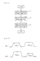
- Fig.8 shows waveforms of the primary and secondary currents I 1 and I 2 .
- the inverter control 116 compares the obtained effective current value [I 2 ] with the selected current value Is to thereby determine the deviation (error, difference) of the measured current from the selected. Then the inverter control 116 computes a second pulse width W 2 that will eliminate or reduce the error. In the second cycle, the inverter control 116 generates a control pulse CP 2 having the second pulse width W 2 to the inverter circuit 100. For third and following cycles, inverter control 116 repeats the operation described above.
- the primary and secondary welding current I 1 and I 2 progressively increases towards the desired level Is (see waveforms shown in the 8th) at the beginning cycles of the welding operation.
- the rise time of the current must be minimized to assure the weld quality and productivity.
- the pulse width W 1 of the control pulses CP for the first cycle of the welding operation is set to a certain initial value Ws.
- the initial pulse width Ws is fixed in two respects. First a plurality of different types of the inverter resistance welding machine having different welding capacity employ the same or common initial value Ws. Second, the initial value Ws is fixed for different settings of the welding current for individual inverter resistance welding operations. Therefore, it is very hard to provide fast and stable rise time of the current for individual welding machines and for individual welding operations.
- pilot welding prior to the actual welding operation.
- the pilot welding procedure involves testing welding operations using different pulse widths.
- the measured current value obtained with an individual pulse width is compared with the selected current value to thereby determine an optimal initial pulse width which thus depends on the selected current value.
- the pilot welding procedure consumes considerable time because it tests the welding machine for the plurality of different pulse widths. Thus it reduces the workability and productivity.
- an object of the invention to provide a method and apparatus for controlling inverter resistance welding, which is capable of providing fast and stable rise time of the current for respective welding operations and for respective welding machines.
- a method of the invention for controlling an inverter resistance welding machine having an inverter in such a manner that primary or secondary current generally maintains near a selected current value by controlling switching of the inverter by a control pulse comprises the steps of;
- An apparatus of the invention for controlling an inverter resistance welding machine having an inverter in such a manner that primary or secondary current generally maintains near a selected current value by controlling switching of the inverter by a control pulse comprises:
- cycle refers to a cycle in which one control pulse is supplied to the inverter. It typically corresponds to one or half cycle of the inverter frequency.
- the maximum current value allowable for the inverter resistance welding machine involved in constant-current control is determined.
- a desired current value (reference value) of welding operation for constant-current control is determined.
- the initial control pulse width used for the first cycle of the welding operation is determined or computed from the maximum allowable current value and the desired preselected current value.
- the inverter switching is controlled by a control pulse having the initial pulse width thus determined.
- the inverter switching is controlled by a subsequent control pulse having a pulse width computed based on the feedback control.
- Fig. 1 shows an arrangement of an inverter resistance welding machine and one embodiment of a control apparatus in accordance with the invention.
- a three-phase commercial AC electric power supply terminal 10 that receives a three-phase AC commercial electric power is connected to an input terminal of a rectifier circuit 12.
- the rectifier circuit 12 generates, at it output, rectified current.
- a smoothing circuit including a coil 14 and a capacitor 16 smoothes the rectified current.
- the smoothed DC current is supplied to an inverter circuit 18.
- the inverter circuit 18 includes switching elements, such as GTR, IGBT or the like, and switches the smoothed DC current into a high frequency AC current of pulses (rectangular pulse).
- the switching operation of the inverter circuit 18 and, therefore the pulse width of the high frequency AC output thereof is controlled by a control pulse CP supplied from CPU 38 via an inverter driver circuit 36.
- the high frequency AC output voltage from the inverter circuit 18 is applied across the primary coil of a welding transformer 20.
- the secondary coil of the welding transformer 20 induces a step-down high frequency AC voltage thereacross.
- the high frequency AC current from the secondary coil of the welding transformer is supplied to a rectifier circuit 24 having a pair of diodes 22a and 22b.
- the rectifier circuit 24 converts the high frequency AC current into DC secondary current I 2 which flows through workpieces 28a and 28b via welding electrodes 26a and 26b.
- the present resistance welding control apparatus comprises a current sensor (eg., toroidal coil) 30, a primary current measuring circuit 32, an analog-to-digital converter 34, a CPU 38, an inverter driver circuit 36, a ROM 40, a RAM 42, a panel controller 44, a panel key 46, a display 48 and an interface circuit 50.
- a current sensor eg., toroidal coil
- the current sensor 30 is provided in the primary circuit of the welding machine between the inverter circuit 18 output and the primary coil of the welding transformer 20 so as to surround a primary electric wire to generate a signal indicative of the waveform of the primary welding current I 1 or the derivative thereof.
- the primary current measuring circuit 32 determines the effective value of the primary current I 1 from the output signal of the current sensor 30 in each half or one cycle.
- the measured value [I 1 ] of the primary current in analog form obtained from the primary current measuring circuit 32 is converted into a corresponding digital signal by the analog-to-digital converter 34.
- the digitized signal of the measured current is received by CPU 38.
- CPU 38 reads the measured current value [I 1 ] of each cycle from the primary current measuring circuit 32 and compares with stored (registered) selected current value [Is] to thereby compute the deviation of the measured current value. Based on the deviation, CPU 38 determines a next pulse width W i+1 in order that the deviation will be cancelled. In the next cycle, CPU generates a control pulse CP i+1 having the pulse width W i+1 thus determined.
- the combination of the current sensor 30, primary current measuring circuit 32, analog-to-digital converter 34, CPU 38 and inverter driver circuit 36 defines a pulse width modulation constant-current control circuit with a feedback loop that controls the switching of the inverter circuit 18 so that the primary current I 1 generally maintains near the selected current value [Is].
- ROM 40 stores programs for controlling CPU 38.
- the stored programs include a control program for providing the constant-current control described above, a display program for providing man-machine interface on the control panel, a key input routine, a communication program for data communication with an external device via the interface circuit 50, and so on.
- RAM 42 stores various selected values as registered data. Further RAM 42 temporarily stores measured results of welding operation, intermediate and final data from CPU 38. The contents of RAM 42 may be held by a backup battery.
- the panel controller 44 receives and transmits signals to and from CPU 38, and keys 46 and a display 48 (e.g., liquid crystal display and LED indicators) disposed on the control panel.
- the interface circuit 50 is connected to CPU 38 via an internal bus.
- the interface circuit 50 is also connected via a communication cable 52 to an external device such as a welding robot controller, weld start switch and/or welding schedule programming unit.
- the panel keys 46 may be operated to enter the maximum current capacity or maximum allowable current value [I MAX ] of the resistance welding machine involved.
- the maximum allowable current value [I MAX ] is intrinsically or inherently determined by the configuration and condition of the resistance welding machine involved. In place of the exact value of the inherent maximum allowable current, approximate value may be entered. If desired, the maximum allowable current may be measured and the measured result may be entered. For instance, the maximum allowable current value [I MAX ] may be determined or computed from the measured current value [I 1 ] when control pulses CP having the maximum pulse width W MAX is inputted to the inverter circuit 18.
- the maximum allowable current value entered from the panel keys 46 may normally be expressed in terms of the primary circuit.
- the ratio of primary to secondary welding current can, however, be determined by the turns ratio of the welding transformer 18.
- the maximum allowable secondary current value may be entered instead.
- CPU 38 may convert or scale it into the maximum allowable primary current.
- Fig.2 is a flow chart showing a process of CPU 38 for entering and storing the maximum allowable current value [I MAX ] and the selected current value [Is].
- the entered maximum allowable current value [I MAX ] is written into RAM 42 at a predetermined storage location for registration (step A 1 ).
- a selected current value [Is] of a particular welding operation is entered (step A 2 ).
- CPU 38 computes an initial pulse width WS from the maximum allowable current value [I MAX ] and the selected current value [Is] according to a predetermined formula, for example, the one (1) given below (step A 3 ).
- Ws W MAX ⁇ IsI MAX in which W MAX indicates the maximum pulse width predefined.
- the initial pulse width Ws defines the pulse width of the first control pulse CP1 which is generated in the first cycle of the welding operation.
- the initial pulse width data Ws, thus computed, is written into RAM 42 at a predetermined storage location.
- selected current value data [Is] may be independently determined.
- CPU repeats steps A 2 and A 3 for respective selected current value data [Is], using the common maximum allowable current value data [I MAX ].
- Fig.3 is a flow chart showing a process of the CPU 38 for providing pulse width modulation control during welding operation.
- CPU 38 When it has received a weld start signal from the external device via the interface circuit 50 (step B 1 ), CPU 38 reads, from storage (RAM 42), the initial pulse width data Ws as well as other parameters (selected current value data, weld time data, etc.,) of the weld schedule responding to the weld start signal (step B 2 ) to start the welding operation. Then CPU 38 generates a first control pulse CP1 having the initial pulse width Ws (step B 3 ).
- the switching elements in the inverter circuit 18 are switched into conducting for a time corresponding to the initial control pulse width Ws, so that AC primary current I 1 stars to flow through the primary circuit and DC secondary current (welding current) I 2 starts to flow through the secondary circuit.
- the primary welding current I1 of the first cycle of the welding operation is measured by the primary current measuring circuit 32 via the current sensor 30.
- CPU 38 received the measured value of the primary current [I 1 ], expressed in RMS (step B 5 ).
- CPU 38 computes the error or deviation of measured current value [I 1 ] from the selected current value [I S ] (step B 6 ).
- CPU 38 computes a new or second control pulse width W 2 from the error so that the error will be cancelled (step B 7 ).
- CPU 38 For the next or second cycle of the welding operation, CPU 38 generates and supplies a control pulse CP 2 having the pulse width W 2 (step B 3 ).
- the switching elements in the inverter circuit 18 are switched into conduction for a time corresponding to the second control pulse width W 2 so that the primary and secondary current I 1 and I 2 of the second cycle will become greater than that of the first cycle.
- the primary current I 1 of the second cycle is measured similarly.
- CPU 38 reads the measured value [I 1 ] thereof (step B 5 ), computes the error of the measured value from the selected current value [Is] (step B 6 ) and computes a third control pulse width W 3 to reduce the error (step B 7 ). Then, for the third cycle of the welding operation, CPU 38 generates a third control pulse CP 3 having the pulse width W 3 (step B 3 ). The process of the steps B 3 to B 7 repeats for subsequent cycles until the weld time has finished (step B 4 ).
- the present resistance welding control apparatus uniquely determines an initial control pulse width W S , corresponding to a selected current value [Is] desired for the welding operation to be performed, from the maximum allowable welding current value [I MAX ] of the inverter resistance welding machine involved .
- the apparatus supplies the inverter circuit 18 with a first control pulse CP1 having the initial pulse width Ws.
- the apparatus supplies the inverter circuit 18 with subsequent control pulses having a pulse width determined from the error of the actual primary current measurement [I 1 ] of a previous cycle from the selected or desired current value [Is].
- welding operation always starts with an appropriate initial pulse width Ws since it is optimized for capacity of the inverter resistance welding machine involved and the desired welding current value [Is] selected for the welding operation to be performed.
- the welding current can reach the desired current value [Is] in a minimum time without experiencing any overshoot. Once established, the welding current maintains near the des ired current level until the welding operation finishes.
- Fig.4 shows waveforms of the secondary current in a sequence of different welding operations with independently selected current values according to a welding schedule.
- the first and second welding operations involve independently selected current values [Is] 1.1 and [Is] 1.2 , respectively.
- the first and second welding operations employ individually selected current values [Is] 2.1 and [Is] 2.2 .
- each indicative of a desired magnitude or level of current initial control pulse widths [Ws] 1.1 , [Ws] 1.2 , [Ws] 2.1 , [Ws] 2.2 etc. are individually determined (steps A 2 and A 3 in Fig.2).
- the inverter switching begins with an initial control pulse width optimized as a function of the desired current level for that welding operation therefor as well as the current capacity of the welding machine (steps B 2 and B 3 in Fig.3).
- a method and apparatus of the invention makes best use of a pulse width modulation constant-current control for an inverter resistance welding machine, thus capable of improving weld quality and productivity.
- a method and apparatus of the invention for control ling inverter resistance welding is particularly suitable for certain types of resistance welding, such as project ion welding and seam welding. in which the welding current must quickly reach the desired level to assure satisfactory weld quality.
- Fig.5 illustrates projection welding.
- One of the workpieces, 28a' may be a plate of first material, say, copper and the other one 28b' may be a second material, say, iron plate.
- the workpieces 28a' and 28b' of such materials are hard to join or weld together.
- one of the workpieces 28a' is formed with a projection R at a position to be joined.
- the projection R experiences concentrated current flowing there through and thus generate a large amount of heat by the resistance thereof.
- a high pressure P is suddenly applied to a pair of electrodes 26a and 26b.
- the projection R is deformed or flatted by pressure to undergo resistance welding.
- the projection welding It is desired for the projection welding that the projection R generates a large amount of heat by resistance immediately after the start of the welding operation. To this end the welding current must rise up in a shortest time as Dossible. This requirement for the projection welding can be successfully met in accordance with the method and apparatus of the invention for controlling the inverter resistance welding. Using the method and apparatus of the invention, the projection welding produces satisfactory weldment.
- Fig.6 illustrates a seam welding of intermittent current type.
- a pair of workpieces 60 and 62 each have a hemisphere 60a, 62a formed with an annular flange 60b, 62b.
- the flanged workpieces 60 and 62 are butted each other.
- the welding current is intermittently and repeatedly applied to respective abutment points F of the workpieces at regular interials.
- the welding current (secondary current) flows cyclically and intermittently as shown in (C) of Fig.6.
- the illustrated embodiment employs a pulse width modulation constant-current control having a feedback loop with respect to the primary current I 1 .
- a current sensor may be provided in the secondary circuit of the welding machine, and a constant-current control may be applied to the secondary current I 2 .
- a dedicated hardware circuit, current measuring circuit 32 is employed to compute the current value (RMS) for each cycle
- a programm-controlled CPU 38 may compute or determine the measured current value of the each cycle.
- the value of the maximum allowable current. I MAX may be updated as required for a change of the configuration of the resistance welding machine and/or aging thereof.
- the formula (1) according to which the initial control pulse width Ws is computed from the maximum allowable current value [I MAX ] and the selected current value [Is] is merely illustrative. Corrections and other conditions may be added to optimally compute the initial pulse width to as a function of the maximum current and selected current values.
- welding operation starts with an initial control pulse width optimized from the capacity of the inverter resistance welding machine and selected current value. Therefore, for an inverter resistance welding machine involved and for a welding operation required, welding current rapidly reaches the selected current level without experiencing overshoot.
- the method and apparatus of the invention makes best use of an pulse width modulation constant-control, and significantly improves weld quality and productivity.
Landscapes
- Engineering & Computer Science (AREA)
- Mechanical Engineering (AREA)
- Generation Of Surge Voltage And Current (AREA)
- Inverter Devices (AREA)
- Dc-Dc Converters (AREA)
Abstract
Description
- This invention relates to a method and apparatus for controlling an inverter resistance welding machine on a constant-current control basis.
- Fig.7 is a circuit diagram of a prior art inverter resistance welding machine. The
inverter circuit 100 includes switching elements such as Giant Transistor (GTR), Insulated Gate Bipoler Transistor(IGBT), or power FET. In response to control pulses CP from theinverter control 116, theinverter circuit 100 switches the supplied DC voltage E into pulsed AC current I1 (primary current) having a high frequency. The pulsed AC current I1 from theinverter circuit 100 is supplied to the primary coil of thewelding transformer 102. As a result, the secondary coil of the transformer supplies a secondary pulsed AC current which is proportional to the primary pulsed AC current I1. The secondary pulsed AC current are converted into direct current I2 by means of therectifier circuit 106 having a pair ofdiodes 104a and 104b. The secondary (DC) current I2 flows intoworkpieces welding electrodes - To control the inverter resistance welding machine, the constant-current control, including a feedback loop such that a constant current is supplied to the workpieces during the welding operation, has been mostly employed. The primary reasons are that the welding current is one of the three major conditions of the resistance welding, the remaining two of which are weld force and weld time, and that a feedback loop of the constant-current control can easily be implemented using a toroidal coil or current transformer for measuring the welding current. The term "constant" within the meaning of the constant-current control refers to the constant in terms of the effective current value, the averaged current value or current peak value.
- An external controller (not shown) supplies a control signal ST directing start of welding to the
inverter control 116 in Fig.7. Then theinverter control 116 generates a first control pulse CP1 having an initial pulse width w1 and supplies it to theinverter circuit 100 for the first cycle of the welding operation. The initial control pulse CP1 turns the switching element in theinverter circuit 100 into conduction for a time corresponding to the initial pulse width w1 of the control pulse CP1. Thus theinverter circuit 100 outputs a corresponding pulse I1 so that, in the secondary circuit of thewelding transformer 102, secondary DC current I2 starts to flow through theworkpieces inverter control 116 determines the effective value [I2] of the secondary current from the secondary current I2 measured through the current sensor (toroidal coil) 118 provided in the secondary circuit. Fig.8 shows waveforms of the primary and secondary currents I1 and I2. - The
inverter control 116 compares the obtained effective current value [I2] with the selected current value Is to thereby determine the deviation (error, difference) of the measured current from the selected. Then theinverter control 116 computes a second pulse width W2 that will eliminate or reduce the error. In the second cycle, theinverter control 116 generates a control pulse CP2 having the second pulse width W2 to theinverter circuit 100. For third and following cycles,inverter control 116 repeats the operation described above. - As long as the effective current value [I2] is smaller than the selected or desired current value [Ig], the pulse width in a pulse train of the control signal CP will progressively extend in time, resulting in the corresponding pulse width expansion of the pulsed AC I1 generated by the
inverter circuit 100. On the other hand, as long as the effective current value [I2] is greater than the selected or desired value [Ig], the pulse width of the control pulses CP will get narrower in time, resulting in the corresponding pulse width compression of the pulsed AC generated by theinverter circuit 100. In this manner constant-current control is performed using a pulse width modulation (PWM) with a feedback loop. - With the PWN constant-current control described above, the primary and secondary welding current I1 and I2 progressively increases towards the desired level Is (see waveforms shown in the 8th) at the beginning cycles of the welding operation. The rise time of the current must be minimized to assure the weld quality and productivity.
- In the prior art, the pulse width W1 of the control pulses CP for the first cycle of the welding operation is set to a certain initial value Ws. The initial pulse width Ws is fixed in two respects. First a plurality of different types of the inverter resistance welding machine having different welding capacity employ the same or common initial value Ws. Second, the initial value Ws is fixed for different settings of the welding current for individual inverter resistance welding operations. Therefore, it is very hard to provide fast and stable rise time of the current for individual welding machines and for individual welding operations.
- In any circumstances, the welding current increasing process must not experience an over shoot in which the welding current significantly exceeds the desired level as shown by a chain line in Fig.9. The overshooting of the welding current tends to produce undesirable splash. To avoid the overshoot, prior art employs a narrower pulse width for the initial pulse width W1 (Ws) of the control pulse CP. However, this necessarily requires an extended rise time of the welding current.
- Some prior art employs pilot welding prior to the actual welding operation. The pilot welding procedure involves testing welding operations using different pulse widths. The measured current value obtained with an individual pulse width is compared with the selected current value to thereby determine an optimal initial pulse width which thus depends on the selected current value. However, the pilot welding procedure consumes considerable time because it tests the welding machine for the plurality of different pulse widths. Thus it reduces the workability and productivity.
- With the above problems in mind, it is, therefore, an object of the invention to provide a method and apparatus for controlling inverter resistance welding, which is capable of providing fast and stable rise time of the current for respective welding operations and for respective welding machines.
- A method of the invention for controlling an inverter resistance welding machine having an inverter in such a manner that primary or secondary current generally maintains near a selected current value by controlling switching of the inverter by a control pulse, comprises the steps of;
- determining maximum allowable primary or secondary current value of the resistance welding machine;
- computing an initial pulse width of the control pulse from the maximum allowable current value and the selected current value;
- supplying the control pulse having the initial pulse width to the inverter for a first cycle of welding operation;
- for a second or subsequent cycle of welding operation, supplying the inverter with the control pulse having a pulse width computed from a deviation of a value of the current measured in a previous cycle of the welding operation from the selected current value.
- An apparatus of the invention for controlling an inverter resistance welding machine having an inverter in such a manner that primary or secondary current generally maintains near a selected current value by controlling switching of the inverter by a control pulse, comprises:
- input means for entering the selected current value and maximum allowable primary or secondary current value of the resistance welding machine;
- storage means for storing the selected current value and the maximum allowable current value inputted from the input means;
- initial pulse width computing means for computing an initial pulse width of the control pulse from the maximum allowable current value and the selected current value;
- current measuring means for measuring the current during welding operation;
- subsequent pulse width computing means for computing deviation of a measured current value measured by the current measuring means from the selected current value to thereby compute a subsequent pulse width of the control pulse; and
- control pulse generating means for supplying the inverter with the control pulse having the pulse width obtained from the initial pulse width computing means in a first cycle of the welding operation and for supplying the inverter with the control pulse having the pulse width obtained from the subsequent pulse width computing means in a subsequent cycle of the welding operation.
- The term "cycle" refers to a cycle in which one control pulse is supplied to the inverter. It typically corresponds to one or half cycle of the inverter frequency.
- In accordance with the invention, the maximum current value allowable for the inverter resistance welding machine involved in constant-current control is determined. A desired current value (reference value) of welding operation for constant-current control is determined. Then the initial control pulse width used for the first cycle of the welding operation is determined or computed from the maximum allowable current value and the desired preselected current value. In a first cycle of the welding operation, the inverter switching is controlled by a control pulse having the initial pulse width thus determined. In any second or subsequent cycle, the inverter switching is controlled by a subsequent control pulse having a pulse width computed based on the feedback control. With the method or apparatus of the invention, welding operation always starts with an optimal pulse width which is optimized for the current capacity of the welding machine involved in the welding operation and the preselected current value of the welding operation, as a function thereof.
- The above and other objects, features and advantages of the invention will become more apparent from the following description taken in conjunction with the drawings in which;
- Fig.1 is block diagram of an inverter resistance welding machine system to which one embodiment of an inverter resistance welding control apparatus of the invention is applied;
- Fig.2 is a flow chart showing a process of CPU in Fig.1 for entering and storing maximum allowable current value and selected welding current value in accordance with the invention;
- Fig.3 is a flow chart of a process of CPU in Fig.1 for providing pulse width modulation control during welding operation in accordance with the invention;
- Fig.4 shows waveforms of the secondary current for different welding schedules which employ independently selected current values for individual welding operations;
- Fig.5 is a view of a projection welding to which a method and apparatus of the invention can advantageously be applied;
- Fig.6 is a view and a diagram of intermittent seam welding to which a method and apparatus of the invention can advantageously be applied;
- Fig.7 is a block diagram showing an arrangement of the prior art inverter resistance welding machine system;
- Fig.8 shows waveforms of primary current and welding current at the beginning cycles of the welding operation, as experienced in the prior art inverter resistance welding control apparatus;
- Fig.9 is a waveform showing an overshoot of the welding current as experienced by the prior art inverter resistance welding machine at beginning cycles of welding operation.
- The invention will now be described in detail with respect to an illustrated embodiment by reference to Figs.1 to 6.
- Fig. 1 shows an arrangement of an inverter resistance welding machine and one embodiment of a control apparatus in accordance with the invention.
- A three-phase commercial AC electric
power supply terminal 10 that receives a three-phase AC commercial electric power is connected to an input terminal of arectifier circuit 12. Therectifier circuit 12 generates, at it output, rectified current. A smoothing circuit including acoil 14 and acapacitor 16 smoothes the rectified current. The smoothed DC current is supplied to aninverter circuit 18. Theinverter circuit 18 includes switching elements, such as GTR, IGBT or the like, and switches the smoothed DC current into a high frequency AC current of pulses (rectangular pulse). The switching operation of theinverter circuit 18 and, therefore the pulse width of the high frequency AC output thereof is controlled by a control pulse CP supplied fromCPU 38 via aninverter driver circuit 36. - The high frequency AC output voltage from the
inverter circuit 18 is applied across the primary coil of awelding transformer 20. The secondary coil of thewelding transformer 20 induces a step-down high frequency AC voltage thereacross. The high frequency AC current from the secondary coil of the welding transformer is supplied to arectifier circuit 24 having a pair ofdiodes rectifier circuit 24 converts the high frequency AC current into DC secondary current I2 which flows throughworkpieces 28a and 28b viawelding electrodes - The present resistance welding control apparatus comprises a current sensor (eg., toroidal coil) 30, a primary
current measuring circuit 32, an analog-to-digital converter 34, aCPU 38, aninverter driver circuit 36, aROM 40, aRAM 42, apanel controller 44, apanel key 46, adisplay 48 and aninterface circuit 50. - The
current sensor 30 is provided in the primary circuit of the welding machine between theinverter circuit 18 output and the primary coil of thewelding transformer 20 so as to surround a primary electric wire to generate a signal indicative of the waveform of the primary welding current I1 or the derivative thereof. The primarycurrent measuring circuit 32 determines the effective value of the primary current I1 from the output signal of thecurrent sensor 30 in each half or one cycle. The measured value [I1] of the primary current in analog form obtained from the primarycurrent measuring circuit 32 is converted into a corresponding digital signal by the analog-to-digital converter 34. The digitized signal of the measured current is received byCPU 38. -
CPU 38 reads the measured current value [I1] of each cycle from the primarycurrent measuring circuit 32 and compares with stored (registered) selected current value [Is] to thereby compute the deviation of the measured current value. Based on the deviation,CPU 38 determines a next pulse width Wi+1 in order that the deviation will be cancelled. In the next cycle, CPU generates a control pulse CPi+1 having the pulse width Wi+1 thus determined. The combination of thecurrent sensor 30, primarycurrent measuring circuit 32, analog-to-digital converter 34,CPU 38 andinverter driver circuit 36 defines a pulse width modulation constant-current control circuit with a feedback loop that controls the switching of theinverter circuit 18 so that the primary current I1 generally maintains near the selected current value [Is]. -
ROM 40 stores programs for controllingCPU 38. The stored programs include a control program for providing the constant-current control described above, a display program for providing man-machine interface on the control panel, a key input routine, a communication program for data communication with an external device via theinterface circuit 50, and so on. -
RAM 42 stores various selected values as registered data.Further RAM 42 temporarily stores measured results of welding operation, intermediate and final data fromCPU 38. The contents ofRAM 42 may be held by a backup battery. Thepanel controller 44 receives and transmits signals to and fromCPU 38, andkeys 46 and a display 48 (e.g., liquid crystal display and LED indicators) disposed on the control panel. - The
interface circuit 50 is connected toCPU 38 via an internal bus. Theinterface circuit 50 is also connected via acommunication cable 52 to an external device such as a welding robot controller, weld start switch and/or welding schedule programming unit. - In the present resistance welding control apparatus, the
panel keys 46 may be operated to enter the maximum current capacity or maximum allowable current value [IMAX] of the resistance welding machine involved. The maximum allowable current value [IMAX] is intrinsically or inherently determined by the configuration and condition of the resistance welding machine involved. In place of the exact value of the inherent maximum allowable current, approximate value may be entered. If desired, the maximum allowable current may be measured and the measured result may be entered. For instance, the maximum allowable current value [IMAX] may be determined or computed from the measured current value [I1] when control pulses CP having the maximum pulse width WMAX is inputted to theinverter circuit 18. - When a feedback control is applied to the primary circuit, as in the present embodiment, the maximum allowable current value entered from the
panel keys 46 may normally be expressed in terms of the primary circuit. The ratio of primary to secondary welding current can, however, be determined by the turns ratio of thewelding transformer 18. Thus the maximum allowable secondary current value may be entered instead. ThenCPU 38 may convert or scale it into the maximum allowable primary current. - Fig.2 is a flow chart showing a process of
CPU 38 for entering and storing the maximum allowable current value [IMAX] and the selected current value [Is]. The entered maximum allowable current value [IMAX] is written intoRAM 42 at a predetermined storage location for registration (step A1). A selected current value [Is] of a particular welding operation is entered (step A2 ). ThenCPU 38 computes an initial pulse width WS from the maximum allowable current value [IMAX] and the selected current value [Is] according to a predetermined formula, for example, the one (1) given below (step A3).
RAM 42 at a predetermined storage location. - For respective welding operations, selected current value data [Is] may be independently determined. In such a case CPU repeats steps A2 and A3 for respective selected current value data [Is], using the common maximum allowable current value data [IMAX].
- Fig.3 is a flow chart showing a process of the
CPU 38 for providing pulse width modulation control during welding operation. - When it has received a weld start signal from the external device via the interface circuit 50 (step B1),
CPU 38 reads, from storage (RAM 42), the initial pulse width data Ws as well as other parameters (selected current value data, weld time data, etc.,) of the weld schedule responding to the weld start signal (step B2) to start the welding operation. ThenCPU 38 generates a first control pulse CP1 having the initial pulse width Ws (step B3). Thus, in the first cycle of the welding operation, the switching elements in theinverter circuit 18 are switched into conducting for a time corresponding to the initial control pulse width Ws, so that AC primary current I1 stars to flow through the primary circuit and DC secondary current (welding current) I2 starts to flow through the secondary circuit. The primary welding current I1 of the first cycle of the welding operation is measured by the primarycurrent measuring circuit 32 via thecurrent sensor 30. ThenCPU 38 received the measured value of the primary current [I1], expressed in RMS (step B5).CPU 38 computes the error or deviation of measured current value [I1] from the selected current value [IS] (step B6 ). ThenCPU 38 computes a new or second control pulse width W2 from the error so that the error will be cancelled (step B7). - For the next or second cycle of the welding operation,
CPU 38 generates and supplies a control pulse CP2 having the pulse width W2 (step B3). Thus, in the second cycle of the welding operation, the switching elements in theinverter circuit 18 are switched into conduction for a time corresponding to the second control pulse width W2 so that the primary and secondary current I1 and I2 of the second cycle will become greater than that of the first cycle. - The primary current I1 of the second cycle is measured similarly.
CPU 38 reads the measured value [I1] thereof (step B5), computes the error of the measured value from the selected current value [Is] (step B6) and computes a third control pulse width W3 to reduce the error (step B7). Then, for the third cycle of the welding operation,CPU 38 generates a third control pulse CP3 having the pulse width W3 (step B3). The process of the steps B3 to B7 repeats for subsequent cycles until the weld time has finished (step B4). - In this manner, the present resistance welding control apparatus uniquely determines an initial control pulse width WS, corresponding to a selected current value [Is] desired for the welding operation to be performed, from the maximum allowable welding current value [IMAX] of the inverter resistance welding machine involved . In the first cycle of the welding operation with the selected current [IS], the apparatus supplies the
inverter circuit 18 with a first control pulse CP1 having the initial pulse width Ws. For the second and subsequent cycles of the welding operation, the apparatus supplies theinverter circuit 18 with subsequent control pulses having a pulse width determined from the error of the actual primary current measurement [I1] of a previous cycle from the selected or desired current value [Is]. - With the arrangement of the present resistance welding control apparatus, welding operation always starts with an appropriate initial pulse width Ws since it is optimized for capacity of the inverter resistance welding machine involved and the desired welding current value [Is] selected for the welding operation to be performed. Thus, the welding current can reach the desired current value [Is] in a minimum time without experiencing any overshoot. Once established, the welding current maintains near the des ired current level until the welding operation finishes.
- Fig.4 shows waveforms of the secondary current in a sequence of different welding operations with independently selected current values according to a welding schedule. For example, according to the welding schedule No .1, the first and second welding operations involve independently selected current values [Is]1.1 and [Is]1.2, respectively. According to the welding schedule No. 2, the first and second welding operations employ individually selected current values [Is]2.1 and [Is]2.2.
- In accordance with the present resistance welding control apparatus, from a maximum allowable current value [IMAX], indicative of the current capacity of the inverter resistance welding machine involved, and from respective selected current values [Is]1.1, [Is]1.2, [Is]2.1, [Is]2.2 etc., each indicative of a desired magnitude or level of current initial control pulse widths [Ws]1.1, [Ws]1.2, [Ws]2.1, [Ws]2.2 etc., are individually determined (steps A2 and A3 in Fig.2). When any particular welding operation of any particular welding schedule starts, the inverter switching begins with an initial control pulse width optimized as a function of the desired current level for that welding operation therefor as well as the current capacity of the welding machine (steps B2 and B3 in Fig.3).
- In this manner, when starting a welding operation, desired one of the initial control pulse widths [Ws] is chosen for desired one of the selected current values [Is] and applied to a pulse width modulation constant-current control so that the current can rise up in a minimum time without experiencing overshoot. Therefore, a method and apparatus of the invention makes best use of a pulse width modulation constant-current control for an inverter resistance welding machine, thus capable of improving weld quality and productivity.
- A method and apparatus of the invention for control ling inverter resistance welding is particularly suitable for certain types of resistance welding, such as project ion welding and seam welding. in which the welding current must quickly reach the desired level to assure satisfactory weld quality.
- Fig.5 illustrates projection welding. One of the workpieces, 28a', may be a plate of first material, say, copper and the other one 28b' may be a second material, say, iron plate. The
workpieces 28a' and 28b' of such materials are hard to join or weld together. In such a case, one of theworkpieces 28a' is formed with a projection R at a position to be joined. At the beginning of the welding operation, the projection R experiences concentrated current flowing there through and thus generate a large amount of heat by the resistance thereof. When the workpiece starts to be melted, a high pressure P is suddenly applied to a pair ofelectrodes - It is desired for the projection welding that the projection R generates a large amount of heat by resistance immediately after the start of the welding operation. To this end the welding current must rise up in a shortest time as Dossible. This requirement for the projection welding can be successfully met in accordance with the method and apparatus of the invention for controlling the inverter resistance welding. Using the method and apparatus of the invention, the projection welding produces satisfactory weldment.
- Fig.6 illustrates a seam welding of intermittent current type. A pair of
workpieces hemisphere annular flange flanged workpieces workpieces electrodes - In such a seam welding, the welding operation is done intermittently and in a short time for each point F to be welded. Thus if the current rises slowly, it will shorten a net weld time so that it is difficult to provide satisfactory joint at individual weld points F. A method and apparatus of the invention for controlling inverter resistance welding can successfully be applied to the intermittent-current seam welding, thus providing short current rise time at respective weld point F and thus yielding satisfactory weldment.
- The illustrated embodiment employs a pulse width modulation constant-current control having a feedback loop with respect to the primary current I1. Instead, a current sensor may be provided in the secondary circuit of the welding machine, and a constant-current control may be applied to the secondary current I2. Whereas, in the illustrated embodiment, a dedicated hardware circuit, current measuring
circuit 32, is employed to compute the current value (RMS) for each cycle, a programm-controlledCPU 38 may compute or determine the measured current value of the each cycle. - The value of the maximum allowable current. IMAX, may be updated as required for a change of the configuration of the resistance welding machine and/or aging thereof. The formula (1) according to which the initial control pulse width Ws is computed from the maximum allowable current value [IMAX] and the selected current value [Is] is merely illustrative. Corrections and other conditions may be added to optimally compute the initial pulse width to as a function of the maximum current and selected current values.
- In accordance with the method and apparatus of the invention for controlling inverter resistance welding. welding operation starts with an initial control pulse width optimized from the capacity of the inverter resistance welding machine and selected current value. Therefore, for an inverter resistance welding machine involved and for a welding operation required, welding current rapidly reaches the selected current level without experiencing overshoot. The method and apparatus of the invention makes best use of an pulse width modulation constant-control, and significantly improves weld quality and productivity.
Claims (2)
- A method for controlling an inverter resistance welding machine having an inverter in such a manner that primary or secondary current generally maintains near a selected current value by controlling switching of the inverter by a control pulse, comprising the steps of;determining maximum allowable primary or secondary current value of the resistance welding machine;computing an initial pulse width of the control pulse from the maximum allowable current value and the selected current value;supplying the control pulse having the initial pulse width to the inverter for a first cycle of welding operation; andfor a second or subsequent cycle of welding operation, supplying the inverter with the control pulse having a pulse width computed from a deviation of a value of the current measured in a previous cycle of the welding operation from the selected current value.
- An apparatus for controlling an inverter resistance welding machine having an inverter in such a manner that primary or secondary current generally maintains near a selected current value by controlling switching of the inverter by a control pulse, comprising:input means for entering the selected current value and maximum allowable primary or secondary current value of the resistance welding machine;storage means for storing the selected current value and the maximum allowable current value inputted from the input means;initial pulse width computing means for computing an initial pulse width of the control pulse which defines switching of the inverter from the maximum allowable current value and the selected current value;current measuring means for measuring the current during welding operation;subsequent pulse width computing means for computing deviation of a measured current value measured by the current measuring means from the selected current value to thereby compute a subsequent pulse width of the control pulse; andcontrol pulse generating means for supplying the inverter with the control pulse having the pulse width obtained from the initial pulse width computing means in a first cycle of the welding operation and for supplying the inverter with the control pulse having the pulse width obtained from the subsequent pulse width computing means in a subsequent cycle of the welding operation.
Applications Claiming Priority (2)
| Application Number | Priority Date | Filing Date | Title |
|---|---|---|---|
| JP216716/95 | 1995-08-02 | ||
| JP21671695A JP3259011B2 (en) | 1995-08-02 | 1995-08-02 | Inverter type resistance welding control method and apparatus |
Publications (2)
| Publication Number | Publication Date |
|---|---|
| EP0756914A2 true EP0756914A2 (en) | 1997-02-05 |
| EP0756914A3 EP0756914A3 (en) | 1997-02-12 |
Family
ID=16692807
Family Applications (1)
| Application Number | Title | Priority Date | Filing Date |
|---|---|---|---|
| EP96305573A Withdrawn EP0756914A3 (en) | 1995-08-02 | 1996-07-30 | Method and apparatus for controlling inverter resistance welding |
Country Status (5)
| Country | Link |
|---|---|
| US (1) | US5786558A (en) |
| EP (1) | EP0756914A3 (en) |
| JP (1) | JP3259011B2 (en) |
| KR (1) | KR100443166B1 (en) |
| CN (1) | CN1074334C (en) |
Cited By (3)
| Publication number | Priority date | Publication date | Assignee | Title |
|---|---|---|---|---|
| CN105414714A (en) * | 2015-12-31 | 2016-03-23 | 上海广为焊接设备有限公司 | Primary constant current circuit of inverter welding machine |
| CN106787926A (en) * | 2016-12-22 | 2017-05-31 | 吉林大学 | A kind of highpowerpulse current generating system |
| CN113098316A (en) * | 2021-05-20 | 2021-07-09 | 哈尔滨工业大学 | Method for controlling output power of diesel generator set under pulse load |
Families Citing this family (14)
| Publication number | Priority date | Publication date | Assignee | Title |
|---|---|---|---|---|
| KR100280700B1 (en) * | 1993-12-29 | 2001-02-01 | 김순택 | Electric resistance welding method |
| US7531621B1 (en) * | 1998-05-05 | 2009-05-12 | Societe De Conseils De Recherches Et D'applications Scientifiques S.A.S. | PTH2 receptor selective compounds |
| KR100470920B1 (en) * | 2001-08-27 | 2005-02-21 | 이호영 | Introduction Wire Resistance Welding Method For Monitor |
| KR100907651B1 (en) * | 2002-12-23 | 2009-07-14 | 주식회사 포스코 | Constant power controller and method for resistance welding machine |
| FR2872074B1 (en) * | 2004-06-28 | 2006-09-29 | Peugeot Citroen Automobiles Sa | METHOD FOR SUPERVISION OF A RESISTANCE WELDING METHOD AND DEVICE FOR IMPLEMENTING SAID METHOD |
| JP2008235997A (en) * | 2007-03-16 | 2008-10-02 | Mitsubishi Electric Corp | Switching circuit |
| US8835795B2 (en) * | 2008-11-14 | 2014-09-16 | Toyota Motor Engineering & Manufacturing North America, Inc. | Method for implementing spatter-less welding |
| AT507774B1 (en) * | 2009-05-14 | 2010-08-15 | Fronius Int Gmbh | METHOD AND DEVICE FOR DETERMINING THE VOLTAGE ON THE ELECTRODES OF A POINT WELDING TONGUE |
| CN102091848B (en) * | 2010-12-21 | 2013-07-31 | 无锡市大德科技有限公司 | Inverter CO2/MAG/MIG welding machine arc control circuit |
| US10065257B2 (en) | 2011-06-23 | 2018-09-04 | Lincoln Global, Inc. | Welding system with controlled wire feed speed during arc initiation |
| CN103008865B (en) * | 2012-12-31 | 2015-02-04 | 天津商科数控设备有限公司 | Process method for pulse width-adjustable AC (Alternating Current)-DC (Direct Current) inverter resistance welding |
| CN104439621B (en) * | 2014-11-05 | 2016-08-31 | 深圳华意隆电气股份有限公司 | One becomes more meticulous Multifunctional welding welding system and control method thereof |
| CN109822200B (en) * | 2019-02-15 | 2021-06-15 | 无锡海菲焊接设备有限公司 | Self-adaptive welding method and system based on cloud platform big data |
| JP7258445B2 (en) * | 2019-09-30 | 2023-04-17 | ダイハツ工業株式会社 | CONTROL DEVICE FOR RESISTANCE WELDING MACHINE, METHOD FOR MONITORING ELECTRICAL CONDITION OF WELDED PORTION, AND METHOD FOR JUDGING GOOD OR FAILURE |
Citations (3)
| Publication number | Priority date | Publication date | Assignee | Title |
|---|---|---|---|---|
| EP0260963A2 (en) * | 1986-09-18 | 1988-03-23 | Kabushiki Kaisha Toshiba | Inverter-type resistance welding machine |
| US4973815A (en) * | 1989-11-02 | 1990-11-27 | Kabushiki Kaisha Nagoya Dengensha | Resistance welder using an inverter |
| GB2267982A (en) * | 1992-06-15 | 1993-12-22 | Honda Motor Co Ltd | Direct current resistance welding. |
Family Cites Families (6)
| Publication number | Priority date | Publication date | Assignee | Title |
|---|---|---|---|---|
| US5229567A (en) * | 1988-11-17 | 1993-07-20 | Honda Giken Kogyo Kabushiki Kaisha | Switching control system for controlling an inverter of a spot resistance welding apparatus |
| JPH0755378B2 (en) * | 1989-02-21 | 1995-06-14 | 小原株式会社 | Inverter resistance welding machine controller |
| JP2801034B2 (en) * | 1989-08-09 | 1998-09-21 | 株式会社テトラック | Resistance welding machine |
| GB2249747B (en) * | 1990-11-07 | 1994-02-09 | Honda Motor Co Ltd | Direct-current resistance welding apparatus and method of controlling welding current thereof |
| EP0581315B1 (en) * | 1992-07-31 | 1998-10-21 | Matsushita Electric Industrial Co., Ltd. | Resistance welding monitor |
| EP0688626B1 (en) * | 1994-05-27 | 2000-02-16 | Kabushiki Kaisha Toshiba | Control equipment for resistance welding machine |
-
1995
- 1995-08-02 JP JP21671695A patent/JP3259011B2/en not_active Expired - Lifetime
-
1996
- 1996-05-02 KR KR1019960014193A patent/KR100443166B1/en not_active IP Right Cessation
- 1996-07-29 US US08/688,291 patent/US5786558A/en not_active Expired - Fee Related
- 1996-07-30 EP EP96305573A patent/EP0756914A3/en not_active Withdrawn
- 1996-08-02 CN CN96112147A patent/CN1074334C/en not_active Expired - Fee Related
Patent Citations (3)
| Publication number | Priority date | Publication date | Assignee | Title |
|---|---|---|---|---|
| EP0260963A2 (en) * | 1986-09-18 | 1988-03-23 | Kabushiki Kaisha Toshiba | Inverter-type resistance welding machine |
| US4973815A (en) * | 1989-11-02 | 1990-11-27 | Kabushiki Kaisha Nagoya Dengensha | Resistance welder using an inverter |
| GB2267982A (en) * | 1992-06-15 | 1993-12-22 | Honda Motor Co Ltd | Direct current resistance welding. |
Cited By (5)
| Publication number | Priority date | Publication date | Assignee | Title |
|---|---|---|---|---|
| CN105414714A (en) * | 2015-12-31 | 2016-03-23 | 上海广为焊接设备有限公司 | Primary constant current circuit of inverter welding machine |
| CN105414714B (en) * | 2015-12-31 | 2017-07-11 | 上海广为焊接设备有限公司 | A kind of primary constant-current circuit of inverter type welder |
| CN106787926A (en) * | 2016-12-22 | 2017-05-31 | 吉林大学 | A kind of highpowerpulse current generating system |
| CN106787926B (en) * | 2016-12-22 | 2019-01-15 | 吉林大学 | A kind of highpowerpulse current generating system |
| CN113098316A (en) * | 2021-05-20 | 2021-07-09 | 哈尔滨工业大学 | Method for controlling output power of diesel generator set under pulse load |
Also Published As
| Publication number | Publication date |
|---|---|
| CN1074334C (en) | 2001-11-07 |
| CN1154281A (en) | 1997-07-16 |
| KR100443166B1 (en) | 2004-09-21 |
| KR970009961A (en) | 1997-03-27 |
| US5786558A (en) | 1998-07-28 |
| EP0756914A3 (en) | 1997-02-12 |
| JPH0947882A (en) | 1997-02-18 |
| JP3259011B2 (en) | 2002-02-18 |
Similar Documents
| Publication | Publication Date | Title |
|---|---|---|
| US5786558A (en) | Method and apparatus for controlling inverter resistance welding | |
| EP0764495B1 (en) | Inverter seam resistance welding electric power supply apparatus | |
| EP2438672B1 (en) | Welding power supply with digital control of duty cycle | |
| EP1219379A2 (en) | Method and apparatus for controlling resistance welding | |
| US4910375A (en) | Inverter-type resistance welding machine | |
| JP3484457B2 (en) | Resistance welding power supply | |
| US4973815A (en) | Resistance welder using an inverter | |
| US7528345B2 (en) | Power supply apparatus for welder | |
| US5523541A (en) | Method and apparatus for controlling constant current for resistance welding | |
| US5938947A (en) | Method of controlling welding current and inverter-controlled DC resistance welding apparatus | |
| JP3669559B2 (en) | Resistance welding machine | |
| CN111630764B (en) | Power supply device and welding power supply device | |
| JPH1085947A (en) | Method and device for controlling resistance welding | |
| JPH0644542Y2 (en) | Inverter resistance welding machine control or measuring device | |
| JPH1177328A (en) | Device and method of controlling quality in resistance spot welding | |
| JPH04300078A (en) | Method and device for controlling inverter type resistance welding | |
| JP2732154B2 (en) | Inverter type resistance welding control method | |
| JP2635783B2 (en) | DC resistance welding equipment | |
| JPH05337655A (en) | Method and device for controlling welding current of resistance welding machine | |
| WO2016038756A1 (en) | Welding current measuring device, resistance welding monitoring device, and resistance welding control device | |
| JPH07266060A (en) | Resistance welding electric source | |
| JPH04300077A (en) | Method and device for controlling resistance welding | |
| JP2928874B2 (en) | Gun pressing detector of arc stud welding equipment | |
| KR100360596B1 (en) | Resistance welding machine | |
| KR960004790B1 (en) | Capacity control apparatus and method of an arc welding machine |
Legal Events
| Date | Code | Title | Description |
|---|---|---|---|
| PUAI | Public reference made under article 153(3) epc to a published international application that has entered the european phase |
Free format text: ORIGINAL CODE: 0009012 |
|
| PUAL | Search report despatched |
Free format text: ORIGINAL CODE: 0009013 |
|
| AK | Designated contracting states |
Kind code of ref document: A2 Designated state(s): CH DE IT LI |
|
| AK | Designated contracting states |
Kind code of ref document: A3 Designated state(s): CH DE IT LI |
|
| 17P | Request for examination filed |
Effective date: 19970805 |
|
| 17Q | First examination report despatched |
Effective date: 19990427 |
|
| GRAG | Despatch of communication of intention to grant |
Free format text: ORIGINAL CODE: EPIDOS AGRA |
|
| GRAG | Despatch of communication of intention to grant |
Free format text: ORIGINAL CODE: EPIDOS AGRA |
|
| GRAG | Despatch of communication of intention to grant |
Free format text: ORIGINAL CODE: EPIDOS AGRA |
|
| GRAH | Despatch of communication of intention to grant a patent |
Free format text: ORIGINAL CODE: EPIDOS IGRA |
|
| GRAH | Despatch of communication of intention to grant a patent |
Free format text: ORIGINAL CODE: EPIDOS IGRA |
|
| STAA | Information on the status of an ep patent application or granted ep patent |
Free format text: STATUS: THE APPLICATION HAS BEEN WITHDRAWN |
|
| 18W | Application withdrawn |
Withdrawal date: 20020719 |