EP0260963A2 - Inverter-type resistance welding machine - Google Patents
Inverter-type resistance welding machine Download PDFInfo
- Publication number
- EP0260963A2 EP0260963A2 EP87308215A EP87308215A EP0260963A2 EP 0260963 A2 EP0260963 A2 EP 0260963A2 EP 87308215 A EP87308215 A EP 87308215A EP 87308215 A EP87308215 A EP 87308215A EP 0260963 A2 EP0260963 A2 EP 0260963A2
- Authority
- EP
- European Patent Office
- Prior art keywords
- control means
- operation amount
- welding machine
- welding
- value
- Prior art date
- Legal status (The legal status is an assumption and is not a legal conclusion. Google has not performed a legal analysis and makes no representation as to the accuracy of the status listed.)
- Granted
Links
Images

Classifications
-
- B—PERFORMING OPERATIONS; TRANSPORTING
- B23—MACHINE TOOLS; METAL-WORKING NOT OTHERWISE PROVIDED FOR
- B23K—SOLDERING OR UNSOLDERING; WELDING; CLADDING OR PLATING BY SOLDERING OR WELDING; CUTTING BY APPLYING HEAT LOCALLY, e.g. FLAME CUTTING; WORKING BY LASER BEAM
- B23K11/00—Resistance welding; Severing by resistance heating
- B23K11/24—Electric supply or control circuits therefor
- B23K11/25—Monitoring devices
- B23K11/252—Monitoring devices using digital means
- B23K11/256—Monitoring devices using digital means the measured parameter being the inter-electrode electrical resistance
-
- H—ELECTRICITY
- H02—GENERATION; CONVERSION OR DISTRIBUTION OF ELECTRIC POWER
- H02M—APPARATUS FOR CONVERSION BETWEEN AC AND AC, BETWEEN AC AND DC, OR BETWEEN DC AND DC, AND FOR USE WITH MAINS OR SIMILAR POWER SUPPLY SYSTEMS; CONVERSION OF DC OR AC INPUT POWER INTO SURGE OUTPUT POWER; CONTROL OR REGULATION THEREOF
- H02M3/00—Conversion of dc power input into dc power output
- H02M3/22—Conversion of dc power input into dc power output with intermediate conversion into ac
- H02M3/24—Conversion of dc power input into dc power output with intermediate conversion into ac by static converters
- H02M3/28—Conversion of dc power input into dc power output with intermediate conversion into ac by static converters using discharge tubes with control electrode or semiconductor devices with control electrode to produce the intermediate ac
Abstract
Description
- This invention relates to an inverter-type resistance welding machine which operates from a high frequency power source. The invention also encompasses a control system and method for the welding machine.
- In a conventional resistance welding machine, a 50Hz or 60Hz alternating current (AC) commercial power source is supplied to the welder through a welding transformer. The level of current flow through the welder electrodes, i.e., weld current, is controlled by phase control of a thyristor with associated control circuitry. Phase control is the process of rapid ON-OFF switching which connects an AC supply to a load for a controlled fraction of each cycle. Thus, the duty cycle of the supply is controlled. Control is accomplished by governing the phase angle of the AC wave at which the thyristor is triggered. The thyristor then conducts for the remainder of the cycle.
- The use of a relatively low frequencey power source (e.g., 50Hz or 60Hz) requires a rather large welding transformer in order to provide the requisite weld current. A large transformer necessarily results in a welding machine which is correspondingly larger in size and heavier in weight. In order to reduce the size of the transformer and effect a reduction in the size and weight of the welding machine, one solution is to use a power source having a relatively high frequency, e.g., in the range of 400Hz to 800Hz.
- The higher frequency power source permits the use of a smaller transformer without sacrificing the amount of weld current which can be delivered to the welding electrodes. Though a higher frequency power source eliminates one problem (the need for a large transformer), it leads to problems in other areas. One such problem has to do with the relatively short period of each cycle of AC voltage due to the higher frequency. The short period of each cycle makes it difficult to provide the necessary phase control over the thyristor because there is insufficient time to consider all of the necessary welding parameters and provide the appropriate phase control response. This problem is especially critical where a microprocessor is used to provide the control function. Accordingly, there is a tendency to refrain from using higher frequency power sources for this reason, the result being that larger size welding transformers are necessary.
- It is, therefor, an object of the present invention to provide a resistance welding machine which can be operated from a high frequency power source which overcomes the problems associated with such machines which are known in the prior art.
- It is another object of the present invention to provide a resistance welding machine in which weld current can be adequately controlled without regard to the frequency of the power source.
- It is a still further object of the present invention to provide a resistance welding machine which can be operated from a high frequency power source which uses a microprocessor to control weld current.
- It is another object of the present invention to provide an inverter-type resistance welding machine and a control system and a method therefore which controls weld current by a half-cycle response with respect to inverter frequency.
- These and other objects of the present invention are achieved by providing phase control of the inverter where a feed forward operation amount is calculated prior to providing an electric current to the weld electrodes. In addition, an integral operation amount is based on a previously calculated value which in effect reduces its present calculation time to zero. Since calculation of the integral operation amount normally consumes a relatively large amount of time, use of a previously calculated value greatly reduces the time period required to provide the proper phase control of the inverter. Thus, a higher frequency power source can be used along with a correspondingly smaller welding transformer. In addition, the welding machine of the present invention is not prone to generating current which can cause deflecting magnetism of the welding transformer and also prevents abnormally high current flow in the inverter.
-
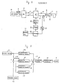
- Figure 1 is a block diagram showing an embodiment of the present invention.
- Figure 2 is a control block diagram which illustrates the operation of the present invention.
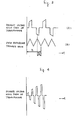
- Figure 3 illustrates the voltage waveforms at various points in the weld current control system of the present invention showing the relationship between the voltage across the primary of the welding transformer and the pulse width modulation reference voltage.
- Figure 4 illustrates the waveform for the desired voltage across the primary of the welding machine transformer.
- Figure 5 is a flow chart illustrating the operation of the CPU in the weld current control system of the present invention.
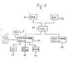
- Figure 6 is a block diagram of the processor used in the weld current control system of the present invention.
- The novel features which are considered as characteristic for this invention are set forth in particular in the appended claims. The invention itself, however, both as to its construction and its method of operation, together with additional objects and advantages thereof, will be best understood from the following description of specific embodiments when read in connection with the accompanying drawings.
- Figure 1 illustrates one embodiment of the present invention. As shown, an alternating
current power source 14 is supplied to rectifier 2 through fusedswitch 1.Rectifier 2 rectifies the AC power supply voltage to a unipolar voltage which is supplied toGTR power inverter 3 onpositive line 15 andnegative line 16.Inverter 3 is a thyristor which has its gate controlled by basedrive control circuit 8, the operation of which will be described below. The voltage waveform at the output ofinverter 3 is shown in Figure 3A and is connected to the primary winding oftransformer 5 bylines transformer 5 is full-wave rectified bydiodes 6 and is supplied toresistance welding electrodes 7. - Pulse width modulator (PWM) 9 provides phase control for
inverter 3 throughbase drive control 8 such that the duty cycle of the voltage waveform at the inverter's output can be varied. Since the level of weld current flow throughwelding electrodes 7 is dependent on the duty cycle of the voltage at the output ofinverter 3,PWM 9 can effectively control weld current flow. The waveform of the control signal fromPWM 9 which is supplied toinverter 3 is shown in Figure 3B. - The operation of
base drive control 8 is controlled by pulse width modulator (PWM) 9 which is in turn controlled byprocessor 10. As shall be discussed in more detail below,processor 10 controls the operation ofPWM 9 in accordance with a stored computer program and data received fromcurrent transformer 4 through A/D converter 12 and commands fromprogram box 11. The purpose ofcurrent transformer 4 is to detect the level of current flow through the primary oftransformer 5. This level is converted to a digital value by A/D converter 12 which is then supplied toprocessor 10. -
Program box 11 allows the user to preset certain welding conditions in advance such as weld current, weld current duration and the like. - Figure 6 is a block diagram illustrating one construction of
processor 10. As Figure 6 shows,processor 10 includes a number of conventional interrelated elements such asRAM memory 61 andROM memory 62 where instructions and temporary data storage areas of a computer program reside.Processor 10 also includes input/output (I/O)peripheral device 64 which allowprocessor 10 to communicate withprogram box 11 and A/D converter 12.Peripheral device 64 may also be used to permit the user to communicate withprocessor 10 through such devices as CRT 65,keyboard 66, andprinter 67. The system may also includemass storage devices 68 which allows the system to store data to and receive programming instructions from such peripheral devices as magnetic floppy disks and tape units. - The heat of
processor 10 is central processing unit (CPU) 63 which supervises the flow of information between the various elements of the system and which perform logic calculations and other functions based on instructions in the computer program stored inRAM 61 and/orROM 62 and data associated with the program.CPU 63 may be selected from a number of microprocessors which are known in the art, including 4-bit, 8-bit, 16-bit or 32-bit types. - The construction of
processor 10 as shown in Figure 6 is merely one embodiment. Other embodiments and arrangements may be used including those which do not have CRT, keyboard and printer capabilities. - With reference to Figure 3 again, time period T1 corresponds to one complete cycle of the voltage appearing at the output of
inverter 3 and two complete cycles of the reference triangle wave control signal appearing at the output ofPWM 9. In the case where the frequence ofAC power source 14 is 700 Hz, the frequency of the voltage at the output ofinverter 3 is also 700 Hz. Thus, the period of time T1 is approximately 1.43 ms and the period of time T2 is approximately 0.36 ms. - In the case where
processor 10 uses an 8-bit microprocessor forCPU 63 operating at a clock frequency of 2.0 MHz for example, the total calculation time needed to determine the phase control ofinverter 3 is approximately 0.5 ms. Since 0.5 ms exceeds the duration of time T2, conventional microprocessor control methods can not be used at this frequency. However, the present invention over comes this problem. - The operation of the welding machine of applicant's invention will now be described in more detail with reference to the control block diagram shown in Figure 2. This block diagram illustrates one cycle of operation of
PWM 9 as controlled byprocessor 10. As pointed out at the outset, an important factor in a resistance welder is control of the amount of weld current which flows through the welding electrodes. - In
block 21 of Figure 2, a desired weld current value is selected by the user viaprogram box 11. The selected weld current value is supplied to feed forwardoperation amount block 24 and to deviation block 23. A feedback amount value fromblock 22 is also supplied to deviation block 23. This value corresponds to the actual weld current then flowing throughwelding electrodes 7 and is provided bycurrent transformer 4 and A/D converter 12.Current transformer 4 detects the level of current flowing through the primary oftransformer 5 and generates a corresponding analogue signal. Since the level of current flow through the secondary oftransformer 5, and thuswelding electrodes 7, is dependent on the level of current flowing through the primary oftransformer 5, the analogue signal fromcurrent transformer 4 accurately reflexes the level of weld current flowing throughwelding electrodes 7. The analogue signal is converted to a corresponding digital signal by A/D converter 12 which is thus the feedback amount value supplied to deviation block 23 fromblock 22. - The desired weld current value and the feedback amount operation value are compared by deviation block 23 which provides a difference amount value which is the difference between the desired weld current value and the feedback amount value. The difference amount value is provided to proportional
operation amount block 25, integraloperation amount block 26 and differenceoperation amount block 27. - Based on the difference value, a proportional operation amount, an integral operation amount and a difference operation amount are determined and then summed in
block 30 to an operation amount as illustrated inblock 28. The operation amount is limited by an operation amount limitation value as illustrated inblock 29 in order to prevent direct current deflecting magnetism of thetransformer 5. This value is then provided as an input toPWM 9 which in turn controls the phase ofinverter 3 accordingly. - As illustrated in figure 4, the operation mount limitation value shown in
block 29 should changed in small steps during each positive and negative half cycle to prevent direct current deflecting magnetism oftransformer 5. As pointed out above, however, a conventional microprocessor controlled welding machine operating in the conventional fashion does not have sufficient response time to provide the necessary small step control. The present invention overcomes this problem as shall be explained with reference to Figure 5. Figure 5 is a flow chart illustration the operation ofprocessor 10. - As shown in Figure 5, a desired
value 21 is established instep 2 and a feedforward operation amount 24 is determined non-selectively instep 3.Operational amount 24 is determined only once prior to electric current being supplied toweld electrodes 7. The feed forwad operation amount value need not be determined for every cycle. A deviation valued 23 is then calculated instep 4, aproportional operation amount 25 and adifferential operation amount 27 are calculated instep 5. Feedforward operation amount 24 and a previously calculatedintegral amount 26 are then added toproportional operation amount 25 anddifferential operation amount 27 in order to obtainoperational amount 28 and an operationalamount limitation value 29 as shown inblock 6. Operationalamount limitation value 29 is set as value Vn. - In
block 7, a determination is made whether the output waveform ofinverter 3 is positive or negative. If negative,PWM 9 is set to the value Vn. If positive, however,PWM 9 is set to the value:
step 10, anintegral operation amount 26 for this cycle is calculated and stored for use during later cycles. Phase control ofinverter 3 is thus achieved by repeating steps 4-10 until the welding process is completed. Using this process, a priorintegral operation amount 26 is used and calculation of a newintegral operation amount 26 is delayed until after a phase control value is provided toPWM 9. Since calculation ofintegral operation amount 26 is rather time consuming, use of the prior calculated amount greatly reduces the time required to provide the proper phase control forinverter 3. Thus, proper phase control can be provided within time period T2 mentioned above. -
Integral operation amount 26 is necessary in order to provide an offset of deviation amount 23 between the desiredvalve 21 and thefeedback value 22. Therefore,integral operation amount 26 has no influence on phase control responses even it is delayed one sampling. - Because the output of the positive cycle from
inverter 3 is given as:
- Obviously, many modifications and variations of the above described preferred embodiment will become apparent to those skilled in the art from a reading of this disclosure. It should be realized that the invention is not limited to the particular apparatus disclosed, but its scope is intended to be governed only be the scope of the appended claims.
Claims (10)
power supply control means adapted to be coupled to a source of AC power for providing a controlled welding current flow;
welding electrodes coupled to said power control means for receiving said controlled current flow;
means for supplying a feedforward operation amount corresponding to a desired welding current before said current is supplied; and
control means coupled to said power supply control means for controlling the operation of said power control means, said control means being arranged to determine a proportion value, an integral value and a difference value in controlling the operation of said power control means, wherein the integral operation time is reduced to approximately zero by employing a calculated value of a previous sampling as an integral operation amount.
providing power supply control means adapted to be coupled to a source of AC power for providing a controlled welding current flow;
providing welding electrodes coupled to said power control means for receiving said controlled current flow;
providing control means coupled to said power supply control means for controlling the operation of said power control means, said control means determines a proportion value, an integral value and a difference value in controlling the operation of said power control means, wherein the feedforward operation amount corresponds to a desired welding current value before said current is supplied and the integral opration time is approximately zero by employing a calculated value of a previous sampling as an integral operation amount.
Applications Claiming Priority (2)
| Application Number | Priority Date | Filing Date | Title |
|---|---|---|---|
| JP61217921A JPH0716306B2 (en) | 1986-09-18 | 1986-09-18 | Inverter resistance welding machine control method |
| JP217921/86 | 1986-09-18 |
Publications (3)
| Publication Number | Publication Date |
|---|---|
| EP0260963A2 true EP0260963A2 (en) | 1988-03-23 |
| EP0260963A3 EP0260963A3 (en) | 1989-05-17 |
| EP0260963B1 EP0260963B1 (en) | 1994-01-05 |
Family
ID=16711817
Family Applications (1)
| Application Number | Title | Priority Date | Filing Date |
|---|---|---|---|
| EP87308215A Expired - Lifetime EP0260963B1 (en) | 1986-09-18 | 1987-09-17 | Inverter-type resistance welding machine |
Country Status (4)
| Country | Link |
|---|---|
| US (1) | US4910375A (en) |
| EP (1) | EP0260963B1 (en) |
| JP (1) | JPH0716306B2 (en) |
| DE (1) | DE3788694T2 (en) |
Cited By (11)
| Publication number | Priority date | Publication date | Assignee | Title |
|---|---|---|---|---|
| US5081993A (en) * | 1987-11-11 | 1992-01-21 | Circulation Research Limited | Methods and apparatus for the examination and treatment of internal organs |
| DE4113117C1 (en) * | 1991-03-06 | 1992-05-07 | Elpatronic Ag, Zug, Ch | Resistance welding using pulse-modulated AC - chopping each half wave in prim. circuit of transformer more than once |
| EP0502478A2 (en) * | 1991-03-06 | 1992-09-09 | Elpatronic Ag | Procedure of resistance welding in particular with alternating non sinusoidal welding current and arrangement for the working of the procedure |
| US5362822A (en) * | 1990-08-03 | 1994-11-08 | The Dow Chemical Company | Mesogenic adducts |
| EP0669182A2 (en) * | 1994-02-25 | 1995-08-30 | Miyachi Technos Corporation | Method for controlling resistance welding using fuzzy reasoning |
| EP0756914A2 (en) * | 1995-08-02 | 1997-02-05 | Miyachi Technos Corporation | Method and apparatus for controlling inverter resistance welding |
| EP0756915A2 (en) * | 1995-08-02 | 1997-02-05 | Miyachi Technos Corporation | Apparatus for controlling inverter resistance welding |
| GB2359152A (en) * | 2000-02-11 | 2001-08-15 | Oxford Magnet Tech | Power Converter Control Loop |
| US6421257B2 (en) | 2000-02-11 | 2002-07-16 | Oxford Magnet Technology Limited | Power converter control loop |
| WO2006002042A2 (en) * | 2004-06-15 | 2006-01-05 | Square D Company | Current control for inductive weld loads |
| CN102218584A (en) * | 2011-06-10 | 2011-10-19 | 李峰华 | Portable central processing unit (CPU) controlled high-power electric welding machine |
Families Citing this family (13)
| Publication number | Priority date | Publication date | Assignee | Title |
|---|---|---|---|---|
| US5166491A (en) * | 1987-12-15 | 1992-11-24 | Kabushiki Kaisha Toshiba | Master computer controlled modular welder, weld control and power unit apparatus and method |
| US5229567A (en) * | 1988-11-17 | 1993-07-20 | Honda Giken Kogyo Kabushiki Kaisha | Switching control system for controlling an inverter of a spot resistance welding apparatus |
| GB2225909B (en) * | 1988-11-17 | 1993-11-24 | Honda Motor Co Ltd | DC resistance welding apparatus |
| US5196668A (en) * | 1988-11-17 | 1993-03-23 | Honda Giken Kogyo Kabushiki Kaisha | DC resistance welding apparatus |
| US5270514A (en) * | 1992-01-08 | 1993-12-14 | Chemetron-Railway Products, Inc. | Method and apparatus for flash butt welding railway rails |
| DE69515083T2 (en) * | 1994-05-27 | 2000-10-12 | Toshiba Kawasaki Kk | Control system for resistance welding machine |
| SE515818C2 (en) * | 1995-03-29 | 2001-10-15 | Torbjoern Staahl | Power supply at welding device for joining roof panels |
| US5589088A (en) * | 1995-06-20 | 1996-12-31 | Medar, Inc. | Method of regulating DC current in resistance welders |
| JPH0985457A (en) * | 1995-09-20 | 1997-03-31 | Miyachi Technos Corp | Power source device for inverter controlled resistance seam welding |
| JP2008047374A (en) * | 2006-08-11 | 2008-02-28 | Mitsumi Electric Co Ltd | Electronic apparatus |
| CN101911460B (en) * | 2007-12-25 | 2013-04-17 | 株式会社村田制作所 | Processor and switching power supply apparatus |
| US9908199B2 (en) * | 2013-03-07 | 2018-03-06 | GM Global Technology Operations LLC | Programmable polarity module for DC resistance spot welding |
| US20160311046A1 (en) * | 2015-04-26 | 2016-10-27 | Antonio Aguilar | Wireless control of a welding machine |
Citations (4)
| Publication number | Priority date | Publication date | Assignee | Title |
|---|---|---|---|---|
| US4419559A (en) * | 1980-10-07 | 1983-12-06 | Tokyo Shibaura Denki Kabushiki Kaisha | Resistive welder having a controlled output voltage unaffected by secondary circuit disconnection |
| JPS59206179A (en) * | 1983-04-08 | 1984-11-21 | Dengensha Mfg Co Ltd | Method and device for controlling compensation of resistance welding voltage |
| JPS60115379A (en) * | 1983-11-25 | 1985-06-21 | Mitsubishi Electric Corp | Control device for resistance welding machine |
| WO1986000035A1 (en) * | 1984-06-15 | 1986-01-03 | Square D Company | Resistance welder |
Family Cites Families (2)
| Publication number | Priority date | Publication date | Assignee | Title |
|---|---|---|---|---|
| US4104724A (en) * | 1977-06-27 | 1978-08-01 | Square D Company | Digital welder control system |
| JPS5939484A (en) * | 1982-08-28 | 1984-03-03 | Honda Motor Co Ltd | Current control device in resistance welding machine |
-
1986
- 1986-09-18 JP JP61217921A patent/JPH0716306B2/en not_active Expired - Lifetime
-
1987
- 1987-09-10 US US07/094,892 patent/US4910375A/en not_active Expired - Fee Related
- 1987-09-17 EP EP87308215A patent/EP0260963B1/en not_active Expired - Lifetime
- 1987-09-17 DE DE87308215T patent/DE3788694T2/en not_active Expired - Fee Related
Patent Citations (4)
| Publication number | Priority date | Publication date | Assignee | Title |
|---|---|---|---|---|
| US4419559A (en) * | 1980-10-07 | 1983-12-06 | Tokyo Shibaura Denki Kabushiki Kaisha | Resistive welder having a controlled output voltage unaffected by secondary circuit disconnection |
| JPS59206179A (en) * | 1983-04-08 | 1984-11-21 | Dengensha Mfg Co Ltd | Method and device for controlling compensation of resistance welding voltage |
| JPS60115379A (en) * | 1983-11-25 | 1985-06-21 | Mitsubishi Electric Corp | Control device for resistance welding machine |
| WO1986000035A1 (en) * | 1984-06-15 | 1986-01-03 | Square D Company | Resistance welder |
Non-Patent Citations (2)
| Title |
|---|
| PATENT ABSTRACTS OF JAPAN, vol. 9, no. 268 (M-424)[1991], 25th October 1985; & JP-A-60 115 379 (MITSUBISHI DENKI K.K.) 21-06-1985 * |
| PATENT ABSTRACTS OF JAPAN, vol. 9, no. 77 (M-369)[1800], 6th April 1985; & JP-A-59 206 179 (DENGENSHIYA SEISAKUSHO K.K.) 21-11-1984 * |
Cited By (18)
| Publication number | Priority date | Publication date | Assignee | Title |
|---|---|---|---|---|
| US5081993A (en) * | 1987-11-11 | 1992-01-21 | Circulation Research Limited | Methods and apparatus for the examination and treatment of internal organs |
| US5362822A (en) * | 1990-08-03 | 1994-11-08 | The Dow Chemical Company | Mesogenic adducts |
| DE4113117C1 (en) * | 1991-03-06 | 1992-05-07 | Elpatronic Ag, Zug, Ch | Resistance welding using pulse-modulated AC - chopping each half wave in prim. circuit of transformer more than once |
| EP0502478A2 (en) * | 1991-03-06 | 1992-09-09 | Elpatronic Ag | Procedure of resistance welding in particular with alternating non sinusoidal welding current and arrangement for the working of the procedure |
| EP0502478A3 (en) * | 1991-03-06 | 1993-02-24 | Elpatronic Ag | Procedure of resistance welding in particular with alternating non sinusoidal welding current and arrangement for the working of the procedure |
| US5489757A (en) * | 1991-03-06 | 1996-02-06 | Elpatronic Ag | Process for resistance welding arrangement for carrying out the process |
| EP0669182A2 (en) * | 1994-02-25 | 1995-08-30 | Miyachi Technos Corporation | Method for controlling resistance welding using fuzzy reasoning |
| EP0669182A3 (en) * | 1994-02-25 | 1995-10-25 | Miyachi Technos Kk | Method for controlling resistance welding using fuzzy reasoning. |
| EP0756914A2 (en) * | 1995-08-02 | 1997-02-05 | Miyachi Technos Corporation | Method and apparatus for controlling inverter resistance welding |
| EP0756915A2 (en) * | 1995-08-02 | 1997-02-05 | Miyachi Technos Corporation | Apparatus for controlling inverter resistance welding |
| EP0756914A3 (en) * | 1995-08-02 | 1997-02-12 | Miyachi Technos Corporation | Method and apparatus for controlling inverter resistance welding |
| EP0756915A3 (en) * | 1995-08-02 | 1997-02-19 | Miyachi Technos Corporation | Apparatus for controlling inverter resistance welding |
| GB2359152A (en) * | 2000-02-11 | 2001-08-15 | Oxford Magnet Tech | Power Converter Control Loop |
| US6421257B2 (en) | 2000-02-11 | 2002-07-16 | Oxford Magnet Technology Limited | Power converter control loop |
| GB2359152B (en) * | 2000-02-11 | 2003-12-17 | Oxford Magnet Tech | Power converter control loop |
| WO2006002042A2 (en) * | 2004-06-15 | 2006-01-05 | Square D Company | Current control for inductive weld loads |
| WO2006002042A3 (en) * | 2004-06-15 | 2006-04-20 | Square D Co | Current control for inductive weld loads |
| CN102218584A (en) * | 2011-06-10 | 2011-10-19 | 李峰华 | Portable central processing unit (CPU) controlled high-power electric welding machine |
Also Published As
| Publication number | Publication date |
|---|---|
| JPS6377380A (en) | 1988-04-07 |
| US4910375A (en) | 1990-03-20 |
| JPH0716306B2 (en) | 1995-02-22 |
| EP0260963B1 (en) | 1994-01-05 |
| EP0260963A3 (en) | 1989-05-17 |
| DE3788694T2 (en) | 1994-04-28 |
| DE3788694D1 (en) | 1994-02-17 |
Similar Documents
| Publication | Publication Date | Title |
|---|---|---|
| EP0260963A2 (en) | Inverter-type resistance welding machine | |
| KR0145356B1 (en) | Method and apparatus for providing welding current from a brushless alternator | |
| EP0669182B1 (en) | Method for controlling resistance welding using fuzzy reasoning | |
| EP1219379A2 (en) | Method and apparatus for controlling resistance welding | |
| US4973815A (en) | Resistance welder using an inverter | |
| US4001539A (en) | Control systems for welding machines | |
| US5786558A (en) | Method and apparatus for controlling inverter resistance welding | |
| US5218182A (en) | Constant current welding power supply with auxilary power source to maintain minimum output current levels | |
| US5523541A (en) | Method and apparatus for controlling constant current for resistance welding | |
| US4475028A (en) | Multi-mode constant potential pulsed welding apparatus | |
| JPH07298515A (en) | Controller for alternator in vehicle | |
| EP0586325A2 (en) | Method and apparatus for TIG welding | |
| US4654503A (en) | Welding current power supply with inductive clipping | |
| JP3669559B2 (en) | Resistance welding machine | |
| JPH0644542Y2 (en) | Inverter resistance welding machine control or measuring device | |
| JPH0631443A (en) | Method for controlling ac tig welding | |
| KR930012171A (en) | Welding control method of arc welding machine and its device | |
| JPH0145279Y2 (en) | ||
| JPH0331499Y2 (en) | ||
| CA2145780C (en) | Dc resistance welding apparatus | |
| JPH01321078A (en) | Pulse arc welding power source | |
| JP2635783B2 (en) | DC resistance welding equipment | |
| AU587165B2 (en) | Resistance welder | |
| EP0570901A2 (en) | Control system for alternating current tig welder | |
| JPH065027Y2 (en) | Inverter resistance welding machine power supply |
Legal Events
| Date | Code | Title | Description |
|---|---|---|---|
| PUAI | Public reference made under article 153(3) epc to a published international application that has entered the european phase |
Free format text: ORIGINAL CODE: 0009012 |
|
| 17P | Request for examination filed |
Effective date: 19870925 |
|
| AK | Designated contracting states |
Kind code of ref document: A2 Designated state(s): DE FR GB SE |
|
| PUAL | Search report despatched |
Free format text: ORIGINAL CODE: 0009013 |
|
| AK | Designated contracting states |
Kind code of ref document: A3 Designated state(s): DE FR GB SE |
|
| 17Q | First examination report despatched |
Effective date: 19910415 |
|
| GRAA | (expected) grant |
Free format text: ORIGINAL CODE: 0009210 |
|
| AK | Designated contracting states |
Kind code of ref document: B1 Designated state(s): DE FR GB SE |
|
| REF | Corresponds to: |
Ref document number: 3788694 Country of ref document: DE Date of ref document: 19940217 |
|
| ET | Fr: translation filed | ||
| PLBE | No opposition filed within time limit |
Free format text: ORIGINAL CODE: 0009261 |
|
| STAA | Information on the status of an ep patent application or granted ep patent |
Free format text: STATUS: NO OPPOSITION FILED WITHIN TIME LIMIT |
|
| 26N | No opposition filed | ||
| EAL | Se: european patent in force in sweden |
Ref document number: 87308215.0 |
|
| PGFP | Annual fee paid to national office [announced via postgrant information from national office to epo] |
Ref country code: GB Payment date: 19970808 Year of fee payment: 11 |
|
| PGFP | Annual fee paid to national office [announced via postgrant information from national office to epo] |
Ref country code: FR Payment date: 19970909 Year of fee payment: 11 |
|
| PGFP | Annual fee paid to national office [announced via postgrant information from national office to epo] |
Ref country code: SE Payment date: 19970918 Year of fee payment: 11 |
|
| PGFP | Annual fee paid to national office [announced via postgrant information from national office to epo] |
Ref country code: DE Payment date: 19970926 Year of fee payment: 11 |
|
| PG25 | Lapsed in a contracting state [announced via postgrant information from national office to epo] |
Ref country code: GB Free format text: LAPSE BECAUSE OF NON-PAYMENT OF DUE FEES Effective date: 19980917 |
|
| PG25 | Lapsed in a contracting state [announced via postgrant information from national office to epo] |
Ref country code: SE Free format text: LAPSE BECAUSE OF NON-PAYMENT OF DUE FEES Effective date: 19980918 |
|
| GBPC | Gb: european patent ceased through non-payment of renewal fee |
Effective date: 19980917 |
|
| EUG | Se: european patent has lapsed |
Ref document number: 87308215.0 |
|
| PG25 | Lapsed in a contracting state [announced via postgrant information from national office to epo] |
Ref country code: FR Free format text: LAPSE BECAUSE OF NON-PAYMENT OF DUE FEES Effective date: 19990531 |
|
| PG25 | Lapsed in a contracting state [announced via postgrant information from national office to epo] |
Ref country code: DE Free format text: LAPSE BECAUSE OF NON-PAYMENT OF DUE FEES Effective date: 19990701 |
|
| REG | Reference to a national code |
Ref country code: FR Ref legal event code: ST |