EP0755797A2 - Aufzeichnungsgerät - Google Patents
Aufzeichnungsgerät Download PDFInfo
- Publication number
- EP0755797A2 EP0755797A2 EP96112030A EP96112030A EP0755797A2 EP 0755797 A2 EP0755797 A2 EP 0755797A2 EP 96112030 A EP96112030 A EP 96112030A EP 96112030 A EP96112030 A EP 96112030A EP 0755797 A2 EP0755797 A2 EP 0755797A2
- Authority
- EP
- European Patent Office
- Prior art keywords
- recording
- discharge means
- recording medium
- ink
- recording apparatus
- Prior art date
- Legal status (The legal status is an assumption and is not a legal conclusion. Google has not performed a legal analysis and makes no representation as to the accuracy of the status listed.)
- Granted
Links
- 230000001360 synchronised effect Effects 0.000 claims abstract description 15
- 239000002184 metal Substances 0.000 claims abstract description 12
- 238000007599 discharging Methods 0.000 claims description 19
- 238000009835 boiling Methods 0.000 claims description 12
- 238000004140 cleaning Methods 0.000 claims description 9
- 239000000976 ink Substances 0.000 description 63
- 230000006866 deterioration Effects 0.000 description 3
- 230000004044 response Effects 0.000 description 3
- 238000010276 construction Methods 0.000 description 2
- 230000000694 effects Effects 0.000 description 2
- 230000005611 electricity Effects 0.000 description 2
- 239000007788 liquid Substances 0.000 description 2
- 230000003068 static effect Effects 0.000 description 2
- 239000000758 substrate Substances 0.000 description 2
- 239000002131 composite material Substances 0.000 description 1
- 239000004020 conductor Substances 0.000 description 1
- 238000007796 conventional method Methods 0.000 description 1
- 230000008021 deposition Effects 0.000 description 1
- 230000002542 deteriorative effect Effects 0.000 description 1
- -1 electrodes Substances 0.000 description 1
- 238000005530 etching Methods 0.000 description 1
- 238000004519 manufacturing process Methods 0.000 description 1
- 230000007246 mechanism Effects 0.000 description 1
- 239000002985 plastic film Substances 0.000 description 1
- 229920006255 plastic film Polymers 0.000 description 1
- 230000001105 regulatory effect Effects 0.000 description 1
- 230000001846 repelling effect Effects 0.000 description 1
- 239000004065 semiconductor Substances 0.000 description 1
- XLYOFNOQVPJJNP-UHFFFAOYSA-N water Substances O XLYOFNOQVPJJNP-UHFFFAOYSA-N 0.000 description 1
Images






Classifications
-
- B—PERFORMING OPERATIONS; TRANSPORTING
- B41—PRINTING; LINING MACHINES; TYPEWRITERS; STAMPS
- B41J—TYPEWRITERS; SELECTIVE PRINTING MECHANISMS, i.e. MECHANISMS PRINTING OTHERWISE THAN FROM A FORME; CORRECTION OF TYPOGRAPHICAL ERRORS
- B41J13/00—Devices or arrangements of selective printing mechanisms, e.g. ink-jet printers or thermal printers, specially adapted for supporting or handling copy material in short lengths, e.g. sheets
- B41J13/10—Sheet holders, retainers, movable guides, or stationary guides
-
- B—PERFORMING OPERATIONS; TRANSPORTING
- B41—PRINTING; LINING MACHINES; TYPEWRITERS; STAMPS
- B41J—TYPEWRITERS; SELECTIVE PRINTING MECHANISMS, i.e. MECHANISMS PRINTING OTHERWISE THAN FROM A FORME; CORRECTION OF TYPOGRAPHICAL ERRORS
- B41J29/00—Details of, or accessories for, typewriters or selective printing mechanisms not otherwise provided for
- B41J29/12—Guards, shields or dust excluders
- B41J29/13—Cases or covers
Definitions
- the present invention relates to a recording apparatus for recording an image by discharging ink from a recording means onto a recording medium.
- recording apparatuses having printer, copier and/or facsimile functions or in recording apparatuses used as an output device for a work station or a composite equipment including a computer, a word processor and the like
- a recording medium such as a sheet or a thin plastic film (for example, an OHP sheet) in response to image information.
- the recording apparatuses are divided into an ink jet recording apparatus, a wire dot recording apparatus, a heat-sensitive recording apparatus, a heat transfer recording apparatus and a laser beam recording apparatus, in accordance with a recording fashion of a recording means.
- the ink jet recording apparatus is designed so that the recording is effected by discharging ink from a recording means (recording head) onto a recording medium and has advantages that the recording means can easily be made compact, that a finer image can be recorded at a high speed, that the image can be recorded on a plain sheet without any specific treatment, that a running cost is inexpensive, that noise can be extremely reduced because of non-impact recording, and that a color image can easily be formed by using different color inks.
- a recording apparatus of line type having a line type recording head in which a plurality of ink discharge openings are disposed along a width-wise direction of the recording medium permits further high speed recording.
- an ink jet recording means for discharging the ink by utilizing energy
- the high density liquid passage arrangement ink discharge opening arrangement
- electro-thermal converter disposed on a substrate, electrodes, liquid passage walls and a top plate by semi-conductor manufacturing process such as etching, deposition, spattering and the like, further compactness of the recording means can be expected.
- a recording medium (not shown) is pinched between a convey roller (convey means) 105 and a feed roller 106 and is conveyed by these rollers.
- a convey roller Convey means
- a feed roller 106
- ink is discharged from the head cartridge, thereby effecting the recording.
- the recording medium is further conveyed by a pair of feed rollers 110, 111 and then is discharged out of the apparatus by a pair of discharge rollers 112, 113 disposed at a downstream side of the pair of feed rollers 110, 111 in a recording medium conveying direction.
- the pair of feed rollers comprise a feed roller (first discharge means) 110 and spurs (first auxiliary discharge means) 111 urged against the feed roller 110
- the pair of discharge rollers comprise a sheet discharge roller (second discharge means) 112 and spurs (second auxiliary discharge means) 113 urged against the sheet discharge roller 112
- the spurs 111, 113 are disposed on a cover 115 which can be opened and closed with respect to a body of the apparatus.
- Each spur is a wheel provided at its periphery with a plurality projections each having a sharp tip end so that the recording medium can be discharged (or conveyed) by one or more projections (with very small contact area).
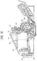
- the cover 115 when the head cartridge 101 is exchanged to a new one due to consumption of ink, the cover 115 is opened by pivoting the cover in an anti-clockwise direction as shown in Fig. 11, thereby permitting the exchange of the head cartridge 101. If the cover 115 is opened by pivoting the cover in a clockwise direction in Fig. 11, the spurs 111 with interfere with the head cartridge 101. Further, in the above-mentioned apparatus, a panel set substrate 120 on which an LCD 121 is disposed is secured at a left portion (Fig. 11) of the apparatus. Accordingly, an operator is in a left side of the recording apparatus.
- the head cartridge 101 is exchanged after the cover 115 is dismounted from the apparatus, if the spurs 111, 113 are subjected to an external force, the water repelling ability of the spurs 111, 113 will be reduced, with the result that the ink adhered to the spurs is re-transferred to the recording medium, thereby deteriorating the recording quality.
- a first object of the present invention is to provide a recording apparatus in which the recording and conveyance of a recording medium can be effected even in a condition that a cover is opened with respect to a body of the recording apparatus, regardless of the kind of recording medium (for example, a single recording sheet or a continuous recording web).
- a second object of the present invention is to provide a recording apparatus in which, in a condition that a cover is opened with respect to a body of the recording apparatus, electric stability (grounding and the like) of elements moved in synchronous with the opening movement of the cover can be ensured.
- a recording apparatus which comprises a recording means for effecting the recording regarding a recording medium, a convey means for conveying the recording medium, a first discharge means disposed in the vicinity of the recording means at a downstream side of the recording means in a recording medium conveying direction, a second discharge means at a downstream side of the first discharge means in the recording medium conveying direction, and first and second auxiliary discharge means urged against the first and second discharge means, respectively, at a first position. It further comprises a second position where the second discharge means and the first auxiliary discharge means are urged against each other.
- the recording apparatus having the above-mentioned arrangement may comprise a guide member for shifting the first auxiliary discharge means from the first position to the second position in a direction substantially parallel to the recording medium conveying direction.
- the first and second auxiliary discharge means may include urging force applying means for urging the first and second auxiliary discharge means against the first and second discharge means, independently, and the recording means may be of type wherein the recording regarding the recording medium is effected by discharging ink.
- the first and second auxiliary discharge means may comprise rotary members, respectively, and may include corresponding cleaning means independently, and the recording means may include electro-thermal converter for generating thermal energy causing film boiling in the ink as an element for generating energy utilized to discharge the ink.
- the present invention further provides a recording apparatus which comprises a recording means for effecting the recording regarding a recording medium, a convey means for conveying the recording medium, a first discharge means disposed in the vicinity of the recording means at a downstream side of the recording means in a recording medium conveying direction, a second discharge means at a downstream side of the first discharge means in the recording medium conveying direction, first and second auxiliary discharge means urged against the first and second discharge means, respectively, at a first position, a second position where the second discharge means and the first auxiliary discharge means are urged against each other, and a guide member for shifting the first auxiliary discharge means from the first position to the second position in a direction substantially parallel to the recording medium conveying direction. It further comprises a cover supported by the recording apparatus for an opening/closing movement with respect to the recording apparatus, and a holding means adapted to rotatably hold the first and second auxiliary discharge means and operated in synchronous with the cover.
- the first and second auxiliary discharge means may include urging force applying means for urging the first and second auxiliary discharge means against the first and second discharge means, independently and the recording means may be of type wherein the recording regarding the recording medium is effected by discharging ink.
- the first and second auxiliary discharge means may comprise rotary members, respectively, and may include corresponding cleaning means independently, and the recording means may include electro-thermal converter for generating thermal energy causing film boiling in the ink as an element for generating energy utilized to discharge the ink.
- a recording apparatus which comprises a recording means for effecting the recording regarding a recording medium, a convey means for conveying the recording medium, a first discharge means disposed in the vicinity of the recording means at a downstream side of the recording means in a recording medium conveying direction, a second discharge means at a downstream side of the first discharge means in the recording medium conveying direction, first and second auxiliary discharge means urged against the first and second discharge means, respectively, at a first position, a second position where the second discharge means and the first auxiliary discharge means are urged against each other, a guide member for shifting the first auxiliary discharge means from the first position to the second position in a direction substantially parallel to the recording medium conveying direction, a cover supported by the recording apparatus for an opening/closing movement with respect to the recording apparatus, and a holding means adapted to rotatably hold the first and second auxiliary discharge means and operated in synchronous with the cover. It further comprising a metal frame on which the first and
- the first and second auxiliary discharge means may include urging force applying means for urging the first and second auxiliary discharge means against the first and second discharge means, independently, and the recording means may be of type wherein the recording regarding the recording medium is effected by discharging ink.
- the first and second auxiliary discharge means may comprise rotary members, respectively, and may include corresponding cleaning means independently, and the recording means may include electro-thermal converter for generating thermal energy causing film boiling in the ink as an element for generating energy utilized to discharge the ink.
- the second discharge means and the first auxiliary discharge means are substantially urged against each other at the second position, when the condition that the cover is opened is assumed to the second position, also in the condition that the cover is opened, the recording medium can be conveyed by the second discharge means and the first auxiliary discharge means, regardless of the kind of the recording medium.
- the guide member for shifting the first auxiliary discharge means from the first position to the second position in the direction substantially parallel to the recording medium conveying direction even when the cover is opened, a bad influence is not affected upon the conveyance of the recording medium, thereby obtaining the good recording result.
- the holding means adapted to rotatably hold the first and second auxiliary discharge means and operated in synchronous with the cover pivotally supported by the recording apparatus, when the cover is opened, since the second position is obtained by the holding means in synchronous with the cover, the operability is improved.
- the metal frame on which the first and second discharge means and the convey means are rested is provided, and the holding means and the metal frame are electrically connected to each other through the guide member both in the first and second positions, even when the cover is opened, the electrical stability of the holding means driven in synchronous with the opening movement of the cover can be ensured.
- the first and second auxiliary discharge means can surely convey the recording medium in the first and second positions.
- first and second auxiliary discharge means comprise rotary members, respectively, and are cleaned by the corresponding cleaning means independently, even when the recording means effects the recording by discharging the ink toward the recording medium, the ink is not re-transferred to the recording medium, thereby preventing the deterioration of the recording quality.
- the recording means includes the electro-thermal converter for generating the thermal energy causing the film boiling in the ink as the element for generating energy utilized to discharge the ink, the discharging of the ink toward the recording medium is performed effectively, thereby obtaining a good recording result.
- the recording apparatus is an ink jet recording apparatus in which the recording is effected by discharging ink from a recording means.
- single sheet referred to as "cut sheet” hereinafter
- a continuous sheet such as a fan-fold sheet
- the ink jet recording apparatus includes an ink jet head (recording means) 20 for effecting the recording by discharging ink toward the recording medium, a convey roller (convey means) 10 for conveying the recording medium, a gap roller (first discharge means) 13 disposed in the vicinity of and a downstream side of the ink jet head 20 in a recording medium conveying direction, a discharge roller (second discharge means) 14 disposed a downstream side of the gap roller 13 in the recording medium conveying direction, spurs as rotary members (first and second auxiliary discharge means) 13a, 14a urged against the gap roller 13 and the discharge roller 14 at a first position, respectively, a spur cover 50 as a cover supported by the apparatus for an opening/closing movement, and a body frame (metal frame) 2 on which the gap roller 13, discharge roller 14 and convey roller 10 are rested.
- an ink jet head (recording means) 20 for effecting the recording by discharging ink toward the recording medium
- a convey roller (convey means) 10 for conveying
- Each spur is a wheel provided at its periphery with a plurality projections each having a sharp tip end so that the recording medium can be discharged (or conveyed) by one or more projections (with very small contact area).
- the spur cover 50 is closed as shown.
- the ink jet head 20 includes electro-thermal converters for generating the thermal energy causing the film boiling in the ink as elements for generating energy utilized to discharge the ink. With this arrangement, the discharging of the ink toward the recording medium is performed effectively, thereby obtaining a good recording result.
- an ASF automatic sheet feeder
- the bins 30a, 30b have same sheet supply mechanisms. That is to say, a plurality of cut sheets (not shown in Fig. 3) stacked on urging plates 31a, 31b are urged toward pick-up rollers 33a, 33b by means of coil springs 32a, 32b.
- the cut sheets are separated and supplied one by one by the rotating pick-up roller 33a or 33b.
- a pinch roller 11 held by a pinch roller holder 5 is urged against the convey roller 10 by a coil-shaped pinch roller spring 65.
- an auxiliary roller 16 held by the pinch roller holder 5 for up-and-down movement is urged against the convey roller 10 by a plate-shaped auxiliary roller spring 68 provided on the pinch roller holder 5.
- the cut sheet supplied from the ASF is conveyed toward a recording position by rotation of the convey roller 10 along a convey path formed around the convey roller.
- a needle roller 12 is held by a needle roller holder 63 and is urged against the convey roller 10 by a plate-shaped needle roller spring 66.
- the needle roller spring 66 is flexed by a projection 61c formed on a release shaft 61 to provide an urging force generated by an elastic spring force around a flexed point 66a.
- the cut sheet is further subjected to a conveying force, so that the cut sheet is conveyed between the ink jet head 20 and a platen 24.
- the conveyance of the cut sheet is effected intermittently at every scan of the ink jet head 20, and a convey amount corresponds to an arrangement length of a plurality of ink discharge openings in the cut sheet conveying direction.
- the recording is effected by the conveyance of the cut sheet per scan of the head and the ink discharge from the head between the successive conveyances.
- the cut sheet on which the recording was effected is conveyed upwardly in the apparatus by means of the gap roller 13 and discharge roller 14 (and the spurs 13a, 14a urged against these rollers) and then is discharged by the spurs 14a.
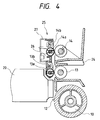
- a spur unit 25 is attached to a spur frame 27 via a spur holder 26 for rotatably holding the spurs 13a, 14a.
- the spur unit 25 is provided with discrete rotatable cleaners (cleaning means) 13b, 14b for removing ink adhered to the spurs 13a, 14a, respectively.
- the spurs 13a, 14a are cleaned, the ink is prevented from being re-transferred to the spurs, thereby preventing the deterioration of the recording quality.
- the spurs 13a, 14a are biased toward the gap roller 13 and the discharge roller 14, respectively, by means of discrete springs (urging force applying means). As a result, the cut sheet can be conveyed positively.
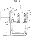
- the position of the spur unit 25 is fixed by a frame cap 28 attached to the spur frame 27 in such a manner that a boss 28a of the cap is guided by a guide groove 40a of a guide member and a cover portion 28c abuts against a boss 40c of the guide member 40.
- the guide member 40 is provided with an earth plate 41 for providing a biasing force directing toward a direction shown by the arrow A in Fig. 6.
- a contact piece 41a of the earth plate 41 is urged against the boss 28a of the frame cap 28 by the biasing force, and a contact piece 41b of the earth plate 41 is contacted with the body frame 2. That is to say, by forming the body frame 2, spur frame 27, frame cap 28 and earth plate 41 from high conductive material (for example, metal), static electricity generated in the sheet convey system can be removed.
- the spur unit 25 is shifted in synchronous with the opening/closing movement of the spur cover 50.
- the shifting movement of the spur unit is regulated by the guide groove 40a of the guide member 40 and the boss 28a of the frame cap 28.
- the spur unit 25 is shifted along the guide groove 40a of the guide member 40 to reach a second position (Fig. 8) where the spurs 13a of the spur unit 25 are urged against the discharge roller 14, thereby providing the conveying force. Accordingly, even in the condition that the spur cover 50 is fully opened, the conveyance of the recording medium (cut sheet or continuous sheet) and the recording to the recording medium can be effected.
- the guide groove 40a of the guide member 40 for guiding the spur unit 25 extends in a direction substantially parallel with the recording medium conveying direction.
- the boss 28a of the frame cap 28 is contacted with another earth plate 41b so that the static electricity can be removed, similar to the closed condition (first position) of the spur cover 50.
- the recording means is not limited to the ink jet recording means, but, a wire dot recording means, a heat-sensitive recording means, a heat-transfer recording means or a laser beam recording means may be used.
- the recording medium can be conveyed by the second discharge means and the first auxiliary discharge means, regardless of the kind of the recording medium.
- the holding means adapted to rotatably hold the first and second auxiliary discharge means and operated in synchronous with the cover pivotally supported by the recording apparatus, when the cover is opened, since the second position is obtained by the holding means in synchronous with the cover, the operability is improved.
- the metal frame on which the first and second discharge means and the convey means are rested is provided, and the holding means and the metal frame are electrically connected to each other through the guide member both in the first and second positions, even when the cover is opened, the electrical stability of the holding means driven in synchronous with the opening movement of the cover can be ensured.
- the first and second auxiliary discharge means can surely convey the recording medium in the first and second positions.
- first and second auxiliary discharge means comprise rotary members, respectively, and are cleaned by the corresponding cleaning means independently, even when the recording means effects the recording by discharging the ink toward the recording medium, the ink is not re-transferred to the recording medium, thereby preventing the deterioration of the recording quality.
- the recording means includes the electro-thermal converter for generating the thermal energy causing the film boiling in the ink as the element for generating energy utilized to discharge the ink, the discharging of the ink toward the recording medium is performed effectively, thereby obtaining a good recording result.
- the present invention provides a recording apparatus in which the recording and conveyance of a recording medium can be effected regardless of a kind of recording medium such as a single sheet or a continuous sheet, in a condition that a cover of the apparatus is opened and electrical stability (grounding and the like) of elements driven in synchronous with the opening movement of the cover can be ensured in the condition that the cover is opened.
- the recording apparatus includes first and second auxiliary discharge means urged against first and second discharge means at a first position, and a second position where the first auxiliary discharge means is substantially urged against the second discharge means. In both the first and second positions, electrical connection between a metal frame and a holding means for holding the first and second auxiliary discharge means can be ensured.
Landscapes
- Ink Jet (AREA)
- Accessory Devices And Overall Control Thereof (AREA)
- Handling Of Cut Paper (AREA)
- Delivering By Means Of Belts And Rollers (AREA)
- Handling Of Sheets (AREA)
Applications Claiming Priority (3)
| Application Number | Priority Date | Filing Date | Title |
|---|---|---|---|
| JP211064/95 | 1995-07-27 | ||
| JP21106495 | 1995-07-27 | ||
| JP7211064A JP2899234B2 (ja) | 1995-07-27 | 1995-07-27 | 記録装置 |
Publications (3)
| Publication Number | Publication Date |
|---|---|
| EP0755797A2 true EP0755797A2 (de) | 1997-01-29 |
| EP0755797A3 EP0755797A3 (de) | 1998-04-01 |
| EP0755797B1 EP0755797B1 (de) | 2001-07-11 |
Family
ID=16599808
Family Applications (1)
| Application Number | Title | Priority Date | Filing Date |
|---|---|---|---|
| EP96112030A Expired - Lifetime EP0755797B1 (de) | 1995-07-27 | 1996-07-25 | Aufzeichnungsgerät |
Country Status (4)
| Country | Link |
|---|---|
| US (1) | US5870127A (de) |
| EP (1) | EP0755797B1 (de) |
| JP (1) | JP2899234B2 (de) |
| DE (1) | DE69613771T2 (de) |
Cited By (1)
| Publication number | Priority date | Publication date | Assignee | Title |
|---|---|---|---|---|
| FR2796001A1 (fr) * | 1999-07-09 | 2001-01-12 | A P S Engineering | Dispositif de deverrouillage d'un compartiment d'un mecanisme ouvrant |
Families Citing this family (2)
| Publication number | Priority date | Publication date | Assignee | Title |
|---|---|---|---|---|
| JPH10129860A (ja) * | 1996-10-31 | 1998-05-19 | Canon Inc | 記録装置 |
| JP4189661B2 (ja) * | 2002-08-14 | 2008-12-03 | セイコーエプソン株式会社 | 記録装置 |
Family Cites Families (6)
| Publication number | Priority date | Publication date | Assignee | Title |
|---|---|---|---|---|
| US4279413A (en) * | 1979-10-17 | 1981-07-21 | Burroughs Corporation | Drive mechanisms for passbooks |
| US4821049A (en) * | 1987-12-02 | 1989-04-11 | Pitney Bowes Inc. | Substrate transport apparatus, especially for mail handling |
| US5291224A (en) * | 1989-10-27 | 1994-03-01 | Canon Kabushiki Kaisha | Sheet feeding apparatus using pairs of spur rollers |
| CA2061878C (en) * | 1991-02-28 | 2001-06-19 | Takashi Saito | Information processing apparatus |
| KR0147859B1 (ko) * | 1992-07-20 | 1998-08-17 | 구보 미츠오 | 잉크제트 프린터 |
| JP3347498B2 (ja) * | 1993-12-30 | 2002-11-20 | キヤノン株式会社 | 記録装置 |
-
1995
- 1995-07-27 JP JP7211064A patent/JP2899234B2/ja not_active Expired - Fee Related
-
1996
- 1996-07-25 EP EP96112030A patent/EP0755797B1/de not_active Expired - Lifetime
- 1996-07-25 DE DE69613771T patent/DE69613771T2/de not_active Expired - Fee Related
- 1996-07-26 US US08/690,392 patent/US5870127A/en not_active Expired - Fee Related
Non-Patent Citations (1)
| Title |
|---|
| None |
Cited By (2)
| Publication number | Priority date | Publication date | Assignee | Title |
|---|---|---|---|---|
| FR2796001A1 (fr) * | 1999-07-09 | 2001-01-12 | A P S Engineering | Dispositif de deverrouillage d'un compartiment d'un mecanisme ouvrant |
| WO2001003939A1 (fr) * | 1999-07-09 | 2001-01-18 | Societe A.P.S. Engineering S.A.R.L. | Dispositif de deverrouillage d'un compartiment d'un mecanisme ouvrant |
Also Published As
| Publication number | Publication date |
|---|---|
| JPH0940255A (ja) | 1997-02-10 |
| DE69613771T2 (de) | 2002-04-25 |
| EP0755797B1 (de) | 2001-07-11 |
| US5870127A (en) | 1999-02-09 |
| EP0755797A3 (de) | 1998-04-01 |
| DE69613771D1 (de) | 2001-08-16 |
| JP2899234B2 (ja) | 1999-06-02 |
Similar Documents
| Publication | Publication Date | Title |
|---|---|---|
| JPH11171155A (ja) | プリンタ | |
| US6419411B1 (en) | Sheet conveying apparatus and recording apparatus using electrostatic attraction | |
| JP3372701B2 (ja) | インクジェット記録装置 | |
| US6520625B1 (en) | Carriage and recording apparatus | |
| EP0359584B1 (de) | Führungseinrichtung für Belege | |
| EP0853003B1 (de) | Drucker | |
| EP0755797B1 (de) | Aufzeichnungsgerät | |
| US5686950A (en) | Mounting device and a recording apparatus including the same | |
| EP0104058B1 (de) | Aufzeichnungsträgerzufuhrvorrichtung für einen Drucker | |
| EP0622215A2 (de) | Linearer Wärmekopf | |
| US6419357B2 (en) | Printing apparatus | |
| US5538237A (en) | Sheet supplying apparatus | |
| JP3691324B2 (ja) | 2連式サーマルプリンタ | |
| JP3697076B2 (ja) | シート搬送装置及び記録装置 | |
| JP2994392B2 (ja) | 記録装置 | |
| JPH09109508A (ja) | 記録装置 | |
| US20020021342A1 (en) | Print medium and printing apparatus | |
| JP3419010B2 (ja) | プリンタ | |
| KR200318544Y1 (ko) | 써멀프린터 | |
| JPH07276726A (ja) | インクジェット記録装置 | |
| JPH0768870A (ja) | 記録装置 | |
| JPS6161987B2 (de) | ||
| GB2159770A (en) | Thermal printer | |
| JP3105686B2 (ja) | プリンタ | |
| JPH08225187A (ja) | 記録装置 |
Legal Events
| Date | Code | Title | Description |
|---|---|---|---|
| PUAI | Public reference made under article 153(3) epc to a published international application that has entered the european phase |
Free format text: ORIGINAL CODE: 0009012 |
|
| AK | Designated contracting states |
Kind code of ref document: A2 Designated state(s): DE FR GB IT |
|
| PUAL | Search report despatched |
Free format text: ORIGINAL CODE: 0009013 |
|
| AK | Designated contracting states |
Kind code of ref document: A3 Designated state(s): DE FR GB IT |
|
| 17P | Request for examination filed |
Effective date: 19980818 |
|
| GRAG | Despatch of communication of intention to grant |
Free format text: ORIGINAL CODE: EPIDOS AGRA |
|
| 17Q | First examination report despatched |
Effective date: 20000821 |
|
| GRAG | Despatch of communication of intention to grant |
Free format text: ORIGINAL CODE: EPIDOS AGRA |
|
| GRAH | Despatch of communication of intention to grant a patent |
Free format text: ORIGINAL CODE: EPIDOS IGRA |
|
| GRAH | Despatch of communication of intention to grant a patent |
Free format text: ORIGINAL CODE: EPIDOS IGRA |
|
| GRAA | (expected) grant |
Free format text: ORIGINAL CODE: 0009210 |
|
| AK | Designated contracting states |
Kind code of ref document: B1 Designated state(s): DE FR GB IT |
|
| PG25 | Lapsed in a contracting state [announced via postgrant information from national office to epo] |
Ref country code: IT Free format text: LAPSE BECAUSE OF FAILURE TO SUBMIT A TRANSLATION OF THE DESCRIPTION OR TO PAY THE FEE WITHIN THE PRESCRIBED TIME-LIMIT;WARNING: LAPSES OF ITALIAN PATENTS WITH EFFECTIVE DATE BEFORE 2007 MAY HAVE OCCURRED AT ANY TIME BEFORE 2007. THE CORRECT EFFECTIVE DATE MAY BE DIFFERENT FROM THE ONE RECORDED. Effective date: 20010711 Ref country code: FR Free format text: LAPSE BECAUSE OF FAILURE TO SUBMIT A TRANSLATION OF THE DESCRIPTION OR TO PAY THE FEE WITHIN THE PRESCRIBED TIME-LIMIT Effective date: 20010711 |
|
| REF | Corresponds to: |
Ref document number: 69613771 Country of ref document: DE Date of ref document: 20010816 |
|
| PG25 | Lapsed in a contracting state [announced via postgrant information from national office to epo] |
Ref country code: GB Free format text: LAPSE BECAUSE OF NON-PAYMENT OF DUE FEES Effective date: 20011011 |
|
| EN | Fr: translation not filed | ||
| REG | Reference to a national code |
Ref country code: GB Ref legal event code: IF02 |
|
| PLBE | No opposition filed within time limit |
Free format text: ORIGINAL CODE: 0009261 |
|
| STAA | Information on the status of an ep patent application or granted ep patent |
Free format text: STATUS: NO OPPOSITION FILED WITHIN TIME LIMIT |
|
| GBPC | Gb: european patent ceased through non-payment of renewal fee |
Effective date: 20011011 |
|
| 26N | No opposition filed | ||
| PGFP | Annual fee paid to national office [announced via postgrant information from national office to epo] |
Ref country code: DE Payment date: 20060720 Year of fee payment: 11 |
|
| PG25 | Lapsed in a contracting state [announced via postgrant information from national office to epo] |
Ref country code: DE Free format text: LAPSE BECAUSE OF NON-PAYMENT OF DUE FEES Effective date: 20080201 |