EP0755660A2 - Ausrichtvorrichtung - Google Patents
Ausrichtvorrichtung Download PDFInfo
- Publication number
- EP0755660A2 EP0755660A2 EP96305492A EP96305492A EP0755660A2 EP 0755660 A2 EP0755660 A2 EP 0755660A2 EP 96305492 A EP96305492 A EP 96305492A EP 96305492 A EP96305492 A EP 96305492A EP 0755660 A2 EP0755660 A2 EP 0755660A2
- Authority
- EP
- European Patent Office
- Prior art keywords
- display
- probe
- cannula
- computer
- line
- Prior art date
- Legal status (The legal status is an assumption and is not a legal conclusion. Google has not performed a legal analysis and makes no representation as to the accuracy of the status listed.)
- Withdrawn
Links
Images


Classifications
-
- A—HUMAN NECESSITIES
- A61—MEDICAL OR VETERINARY SCIENCE; HYGIENE
- A61B—DIAGNOSIS; SURGERY; IDENTIFICATION
- A61B17/00—Surgical instruments, devices or methods
- A61B17/16—Instruments for performing osteoclasis; Drills or chisels for bones; Trepans
- A61B17/17—Guides or aligning means for drills, mills, pins or wires
- A61B17/1707—Guides or aligning means for drills, mills, pins or wires using electromagnetic effects, e.g. with magnet and external sensors
-
- A—HUMAN NECESSITIES
- A61—MEDICAL OR VETERINARY SCIENCE; HYGIENE
- A61B—DIAGNOSIS; SURGERY; IDENTIFICATION
- A61B17/00—Surgical instruments, devices or methods
- A61B17/16—Instruments for performing osteoclasis; Drills or chisels for bones; Trepans
- A61B17/17—Guides or aligning means for drills, mills, pins or wires
- A61B17/1703—Guides or aligning means for drills, mills, pins or wires using imaging means, e.g. by X-rays
-
- A—HUMAN NECESSITIES
- A61—MEDICAL OR VETERINARY SCIENCE; HYGIENE
- A61B—DIAGNOSIS; SURGERY; IDENTIFICATION
- A61B17/00—Surgical instruments, devices or methods
- A61B17/16—Instruments for performing osteoclasis; Drills or chisels for bones; Trepans
- A61B17/17—Guides or aligning means for drills, mills, pins or wires
- A61B17/1725—Guides or aligning means for drills, mills, pins or wires for applying transverse screws or pins through intramedullary nails or pins
-
- A—HUMAN NECESSITIES
- A61—MEDICAL OR VETERINARY SCIENCE; HYGIENE
- A61B—DIAGNOSIS; SURGERY; IDENTIFICATION
- A61B17/00—Surgical instruments, devices or methods
- A61B17/34—Trocars; Puncturing needles
- A61B17/3403—Needle locating or guiding means
-
- A—HUMAN NECESSITIES
- A61—MEDICAL OR VETERINARY SCIENCE; HYGIENE
- A61B—DIAGNOSIS; SURGERY; IDENTIFICATION
- A61B34/00—Computer-aided surgery; Manipulators or robots specially adapted for use in surgery
- A61B34/70—Manipulators specially adapted for use in surgery
-
- A—HUMAN NECESSITIES
- A61—MEDICAL OR VETERINARY SCIENCE; HYGIENE
- A61B—DIAGNOSIS; SURGERY; IDENTIFICATION
- A61B90/00—Instruments, implements or accessories specially adapted for surgery or diagnosis and not covered by any of the groups A61B1/00 - A61B50/00, e.g. for luxation treatment or for protecting wound edges
- A61B90/39—Markers, e.g. radio-opaque or breast lesions markers
Definitions
- THE PRESENT INVENTION relates to an alignment apparatus, for use when seeking to align a guide or cannula with a predetermined direction.
- One embodiment of the invention comprises a robotically controlled apparatus intended to align a guide or cannula with a predetermined direction.
- Robotically controlled apparatus is now finding many applications and, in particular, is finding applications within the operating theatre. It is often desired to align a cannula with a predetermined direction and to insert a probe or operating implement into a patient by a predetermined distance through the cannula. For example, in connection with hip operations, it is often desirable to be able to drill into the top part of the femur along a predetermined direction. This is but one application of a robotically controlled apparatus in the operating theatre.
- the present invention seeks to provide a robotically controlled apparatus that can align a cannula with a predetermined direction.
- an alignment apparatus comprising positioning means supporting a linear cannula or guide, and adapted to position the cannula or guide, the cannula or guide, or an optional linear, a probe within the cannula, having an end and having at least one point marked thereon so as to be visible in an X-ray image thereof, an X-ray apparatus adapted to take X-ray images in two orthogonal planes, a display adapted to display said X-ray images, means to identify, on the displayed images, a line with which the probe is to be aligned, the display being associated with a computer, means being provided to store, in the memory of the computer, data concerning specific selected points on the display, which points comprise at least points present on the image of the probe present on the display and points present on a line on the display with which the probe is to be aligned, the computer being adapted to determine the movement to be effected by the positioning means to align the cannula with the desired line.
- control means are provided to enable an operator to control the position of a marker on said display, so that the marker can be moved to points in the image, the positions of which are to be stored in the memory of the computer.
- control means can be used to create, and display, the line with which the probe is to be aligned.
- the positioning means comprise a robot, said computer controlling the robot.
- a component of a robotically controlled apparatus is an X-ray device capable of taking X-ray images of a patient 1 in two orthogonal directions.
- the apparatus consists of a support 2 which supports a housing 3 containing a drive mechanism.
- the drive mechanism is adapted to drive a substantially "C"-shaped support frame 4 between two alternate positions.
- an X-ray emitter 5 carried on the support frame is located substantially above the patient 1 and an X-ray receiving sensor 6 is located beneath the patient.
- the X-ray sensor 6 is provided with a cross-wire which lies in the plane of the "C"-frame 4.
- the apparatus of Figure 1 is such that the "C"-frame 4 may be moved to an alternate position in which the X-ray emitter 5 and the X-ray sensor 6 are located on either side of the patient, lying in a horizontal plane.
- a "vertical" X-ray view sometimes called an Anterior-Posterior, or AP view
- AP view an Anterior-Posterior
- a "horizontal" X-ray view sometimes called the Lateral or LAT view
- Alternative X-ray arrangements may be provided which give the same effect.
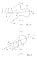
- FIG 2 is a diagrammatic representation of a positioning means, which comprises a robot which supports a cannula or guide, and an associated probe, and which can position the cannula and probe.
- a cannula 10 is illustrated which is a linear element which contains a telescopically movable linear probe 11.
- the probe 11 is provided with two notches 12,13 in its outer surface, which are provided so as to define points on the probe which are visible in an X-ray image of the probe for a purpose that will become clear later. It is preferred that the distance between the notch 13 and the end 14 of the probe is at least substantially equal to the distance between the notch 12 and the notch 13. Alternatively, the probe may be omitted and the markings may be provided on the cannula.
- the cannula 10 and the degree of telescopic extension of the probe 11 relative to the cannula 10 are controlled by a robot 15.
- the precise nature of the robot is not critical to the present invention.
- the robot is controlled by a computer 16 which has a display screen 17 and which is also associated with a mouse or other control arrangement 18.
- An X-ray apparatus 19, such as the X-ray apparatus illustrated in Figure 1 is connected to the computer, such that the image received by the X-ray sensor 6 can be displayed on the screen of the computer.
- the robot In use of the apparatus the robot is initially activated to bring the probe 11 into approximate alignment with the part of the patient 1 where an operating tool is to be introduced into the patient so that the probe is located between the X-ray emitter 5 and the X-ray sensor 6.
- X-ray images both "vertical” and “horizontal", are taken of the part of the patient to be treated and the probe.
- the "C"-frame 4 is rotated by 90° after the first image is taken and before the second image is taken. The images are displayed sequentially or simultaneously upon the computer screen.
- the mouse 18 is used to control the position of a marker on the display screen and the marker is brought into alignment with various parts of the displayed image under the control of the operator of the system, and the mouse is activated to store, within the appropriate memory of the computer, information regarding the various parts of the image.
- the computer is then able to determine the position of the probe relative to the position that it is to adopt, and can move the probe appropriately.
- Figure 3 which is a "vertical" view (or “AP view”) of part of a patient
- the top part of the femur 20 of the patient is visible.
- the cross-wire 21 that is present on the sensor 6 can also be seen, and the probe 11 is also visible.
- the end 14 of the probe is clearly visible as are the notches 12 and 13.
- the operator of the device traces the line of the probe 11 indicating at least the positions on the screen of the notches 12,13 and the end of the probe 14. Also, the position of the wire 21 on the screen is indicated, possibly by indicating two spaced apart points 22,23 present on the wire.
- the computer 16 may be programmed to generate, upon the screen, a line 25 representing an extension of the probe 11. This extension may intersect the line 24 at a point 26.
- the point 26 may also be specifically indicated to the computer by use of the mouse, but the computer program may itself be capable of determining this particular point.
- Figure 4 is a representation of the image on the screen of the display when the "horizontal" X-ray view (or “LATERAL view”) is taken. Again the probe 11 can be seen, and again the end 14 of the probe is clearly visible together with the notches 12 and 13. The same procedure as adopted when the display of Figure 3 was on the screen is followed, the mouse and in indicator on the screen again being used to enable the computer to store, within its memory, information concerning the position of the probe 11. Again the position of the wire 21 on the screen is indicated, again by possibly identifying clearly the position of the points such as the points 22 and 23.
- the line 24 with which the cannula is to be aligned may effectively be recorded within the memory of the computer, particularly by storing information concerning the position of the points 25 and 26.
- the computer may generate, upon the screen, a line 27 representing an extension of the probe 11, with the line 27 intersecting the line 24 at the point 28, but the point 28 may again be indicated by use of the marker on the screen as controlled by the mouse.
- the computer program is adapted to calculate the absolute position of the line 24 which, because it has been defined in two orthogonal planes (i.e. the plane of Figure 3 and the plane of Figure 4) has been defined absolutely.
- the computer then calculates the repositioning that is necessary for the cannula to align the cannula accurately with the line 24.
- the robot then executes the appropriate movement.
- the X-ray procedure may be repeated to ensure that the cannula is indeed accurately aligned with the intended line of operation.
- An appropriate operating tool may then be inserted into the patient through the cannula.
- Figure 5 is the "AP view” and Figure 6 is the “LAT view”.
- the mouse is used to control the position of a marker to identify, on the displayed images, the position of the probe and the position of the cross-wire
- the computer may be provided with an image processing and identifying capability.
- the computer may thus be able to process the image and identify both the probe (or the cannular) and also the cross-wire, without any human intervention. It will, however, still be necessary for the "surgeon's line" to be marked on the displayed images under human control.
- the positioning means which initially support the cannular or guide, and which can position the cannular or guide comprises a robot
- an alignment apparatus in accordance with the invention may be utilised in conjunction with alternative forms of positioning means, such as a positioning means which is manually controlled.
- the computer would determine the movement to be effected by the positioning means to align the cannular with the desired line, and would provide, on a display, an appropriate instruction.
- the positioning means supporting the linear cannular many be provided with adjusting wheels, rotation of which controls the orientation of the linear cannular in three dimensional space.
- the computer in such a situation may provide specific instructions as to which adjusting wheels are to be actuated, and the degree of rotation to be imparted to each adjusting wheel.
Landscapes
- Health & Medical Sciences (AREA)
- Life Sciences & Earth Sciences (AREA)
- Surgery (AREA)
- Engineering & Computer Science (AREA)
- Nuclear Medicine, Radiotherapy & Molecular Imaging (AREA)
- Public Health (AREA)
- Biomedical Technology (AREA)
- Heart & Thoracic Surgery (AREA)
- Medical Informatics (AREA)
- Molecular Biology (AREA)
- Animal Behavior & Ethology (AREA)
- General Health & Medical Sciences (AREA)
- Veterinary Medicine (AREA)
- Oral & Maxillofacial Surgery (AREA)
- Dentistry (AREA)
- Orthopedic Medicine & Surgery (AREA)
- Pathology (AREA)
- Robotics (AREA)
- Physics & Mathematics (AREA)
- Electromagnetism (AREA)
- Radiology & Medical Imaging (AREA)
- Apparatus For Radiation Diagnosis (AREA)
- Accommodation For Nursing Or Treatment Tables (AREA)
- Analysing Materials By The Use Of Radiation (AREA)
- Media Introduction/Drainage Providing Device (AREA)
Applications Claiming Priority (2)
| Application Number | Priority Date | Filing Date | Title |
|---|---|---|---|
| GB9515509 | 1995-07-28 | ||
| GB9515509A GB2303942A (en) | 1995-07-28 | 1995-07-28 | Aligning cannula or guide with line on X-ray images |
Publications (2)
| Publication Number | Publication Date |
|---|---|
| EP0755660A2 true EP0755660A2 (de) | 1997-01-29 |
| EP0755660A3 EP0755660A3 (de) | 1997-03-26 |
Family
ID=10778417
Family Applications (1)
| Application Number | Title | Priority Date | Filing Date |
|---|---|---|---|
| EP96305492A Withdrawn EP0755660A3 (de) | 1995-07-28 | 1996-07-26 | Ausrichtvorrichtung |
Country Status (6)
| Country | Link |
|---|---|
| EP (1) | EP0755660A3 (de) |
| JP (1) | JPH09173350A (de) |
| KR (1) | KR970007701A (de) |
| CA (1) | CA2182747A1 (de) |
| GB (1) | GB2303942A (de) |
| NO (1) | NO963167L (de) |
Cited By (9)
| Publication number | Priority date | Publication date | Assignee | Title |
|---|---|---|---|---|
| WO1998037827A3 (en) * | 1998-02-16 | 1998-12-03 | Koninkl Philips Electronics Nv | Image-guided surgery system |
| WO1999000066A1 (en) * | 1997-06-30 | 1999-01-07 | Neorad A/S | Method and apparatus for assisting percutaneous computed tomography-guided surgical activity |
| WO1999058067A1 (de) * | 1998-05-08 | 1999-11-18 | Eska Implants Gmbh & Co. | Vorrichtung zur präparation eines menschlichen röhrenknochens für die implantation eines knochenimplantates sowie verfahren zum betreiben dieser vorrichtung |
| US6006127A (en) * | 1997-02-28 | 1999-12-21 | U.S. Philips Corporation | Image-guided surgery system |
| EP0923906A3 (de) * | 1997-12-19 | 2000-02-02 | Howmedica Inc. | Zielgerät für Implantatvorrichtungen und Verfahren zu dessen Gebrauch |
| WO2001064124A1 (en) * | 2000-03-01 | 2001-09-07 | Surgical Navigation Technologies, Inc. | Multiple cannula image guided tool for image guided procedures |
| WO2002041794A1 (en) * | 2000-11-24 | 2002-05-30 | Neorad A/S | An apparatus for light beam guided biopsy |
| CN100562294C (zh) * | 2004-04-08 | 2009-11-25 | 泰雷欧斯有限公司 | 用于正确定位骨髓钉的远端锁紧螺钉的自动定点装置 |
| US8795287B2 (en) | 2007-02-08 | 2014-08-05 | Zimmer, Inc. | Targeting device |
Families Citing this family (4)
| Publication number | Priority date | Publication date | Assignee | Title |
|---|---|---|---|---|
| EP1885274B1 (de) * | 2005-06-02 | 2018-04-25 | Orthosoft, Inc. | Beinausrichtung für die messung von chirurgischen parametern bei der hüftersatzchirurgie |
| GB2428110A (en) * | 2005-07-06 | 2007-01-17 | Armstrong Healthcare Ltd | A robot and method of registering a robot. |
| JP4517004B2 (ja) * | 2008-06-16 | 2010-08-04 | ノリー株式会社 | 注射針誘導装置 |
| DE102017223598B4 (de) | 2017-12-21 | 2021-05-20 | Siemens Healthcare Gmbh | Verfahren zur Registrierung beim Einstellen einer Ausrichtung eines Instruments und Robotersystem |
Family Cites Families (8)
| Publication number | Priority date | Publication date | Assignee | Title |
|---|---|---|---|---|
| US4722336A (en) * | 1985-01-25 | 1988-02-02 | Michael Kim | Placement guide |
| US4750487A (en) * | 1986-11-24 | 1988-06-14 | Zanetti Paul H | Stereotactic frame |
| US5050608A (en) * | 1988-07-12 | 1991-09-24 | Medirand, Inc. | System for indicating a position to be operated in a patient's body |
| FR2660185B1 (fr) * | 1990-03-30 | 1998-04-17 | Medirand Inc | Systeme et procede destines a indiquer une position devant etre operee dans le corps d'un patient. |
| US5279309A (en) * | 1991-06-13 | 1994-01-18 | International Business Machines Corporation | Signaling device and method for monitoring positions in a surgical operation |
| US5330485A (en) * | 1991-11-01 | 1994-07-19 | Clayman David A | Cerebral instrument guide frame and procedures utilizing it |
| US5389101A (en) * | 1992-04-21 | 1995-02-14 | University Of Utah | Apparatus and method for photogrammetric surgical localization |
| FR2709656B1 (fr) * | 1993-09-07 | 1995-12-01 | Deemed Int Sa | Installation pour opération de microchirurgie assistée par ordinateur et procédés mis en Óoeuvre par ladite installation. |
-
1995
- 1995-07-28 GB GB9515509A patent/GB2303942A/en not_active Withdrawn
-
1996
- 1996-07-26 EP EP96305492A patent/EP0755660A3/de not_active Withdrawn
- 1996-07-26 CA CA002182747A patent/CA2182747A1/en not_active Abandoned
- 1996-07-27 KR KR1019960030781A patent/KR970007701A/ko not_active Withdrawn
- 1996-07-29 NO NO963167A patent/NO963167L/no unknown
- 1996-07-29 JP JP8199268A patent/JPH09173350A/ja active Pending
Cited By (17)
| Publication number | Priority date | Publication date | Assignee | Title |
|---|---|---|---|---|
| US6006127A (en) * | 1997-02-28 | 1999-12-21 | U.S. Philips Corporation | Image-guided surgery system |
| WO1999000066A1 (en) * | 1997-06-30 | 1999-01-07 | Neorad A/S | Method and apparatus for assisting percutaneous computed tomography-guided surgical activity |
| US6021342A (en) * | 1997-06-30 | 2000-02-01 | Neorad A/S | Apparatus for assisting percutaneous computed tomography-guided surgical activity |
| US6334067B1 (en) | 1997-06-30 | 2001-12-25 | Neorad A/S | Method and apparatus for assisting percutaneous computed tomography-guided surgical activity |
| US6520969B2 (en) | 1997-12-19 | 2003-02-18 | Stryker Technologies Corporation | Guide-pin placement device |
| EP0923906A3 (de) * | 1997-12-19 | 2000-02-02 | Howmedica Inc. | Zielgerät für Implantatvorrichtungen und Verfahren zu dessen Gebrauch |
| US6036696A (en) * | 1997-12-19 | 2000-03-14 | Stryker Technologies Corporation | Guide-pin placement device and method of use |
| US6214013B1 (en) | 1997-12-19 | 2001-04-10 | Stryker Technologies Corporation | Method of using a guide-pin placement device |
| WO1998037827A3 (en) * | 1998-02-16 | 1998-12-03 | Koninkl Philips Electronics Nv | Image-guided surgery system |
| WO1999058067A1 (de) * | 1998-05-08 | 1999-11-18 | Eska Implants Gmbh & Co. | Vorrichtung zur präparation eines menschlichen röhrenknochens für die implantation eines knochenimplantates sowie verfahren zum betreiben dieser vorrichtung |
| WO2001064124A1 (en) * | 2000-03-01 | 2001-09-07 | Surgical Navigation Technologies, Inc. | Multiple cannula image guided tool for image guided procedures |
| US10898153B2 (en) | 2000-03-01 | 2021-01-26 | Medtronic Navigation, Inc. | Multiple cannula image guided tool for image guided procedures |
| WO2002041794A1 (en) * | 2000-11-24 | 2002-05-30 | Neorad A/S | An apparatus for light beam guided biopsy |
| GB2384439A (en) * | 2000-11-24 | 2003-07-30 | Neorad As | An apparatus for light beam guided biopsy |
| GB2384439B (en) * | 2000-11-24 | 2004-06-23 | Neorad As | An apparatus for light beam guided biopsy |
| CN100562294C (zh) * | 2004-04-08 | 2009-11-25 | 泰雷欧斯有限公司 | 用于正确定位骨髓钉的远端锁紧螺钉的自动定点装置 |
| US8795287B2 (en) | 2007-02-08 | 2014-08-05 | Zimmer, Inc. | Targeting device |
Also Published As
| Publication number | Publication date |
|---|---|
| NO963167D0 (no) | 1996-07-29 |
| EP0755660A3 (de) | 1997-03-26 |
| NO963167L (no) | 1997-01-29 |
| JPH09173350A (ja) | 1997-07-08 |
| CA2182747A1 (en) | 1997-01-29 |
| GB2303942A (en) | 1997-03-05 |
| KR970007701A (ko) | 1997-02-21 |
| GB9515509D0 (en) | 1995-09-27 |
Similar Documents
| Publication | Publication Date | Title |
|---|---|---|
| US5799055A (en) | Apparatus and method for planning a stereotactic surgical procedure using coordinated fluoroscopy | |
| US5305203A (en) | Computer-aided surgery apparatus | |
| US5776143A (en) | Stereostatic pointing device | |
| DE69534862T2 (de) | Chirurgische Navigationsanordnung einschliesslich Referenz- und Ortungssystemen | |
| US5080662A (en) | Spinal stereotaxic device and method | |
| KR100695471B1 (ko) | 수술도구 위치 설정용 다자유도 로봇 | |
| JP4220780B2 (ja) | 手術システム | |
| US5748767A (en) | Computer-aided surgery apparatus | |
| EP0469966B1 (de) | Computerunterstützte chirurgische Vorrichtung | |
| US4608977A (en) | System using computed tomography as for selective body treatment | |
| EP0677278B1 (de) | Stereotaktischer Adapter sowie Verfahren zu dessen Betrieb | |
| DE60318996T2 (de) | Apparat zur Positionsbestimmung | |
| AU2016203364B2 (en) | Alignment apparatus for use in hip arthroplasty | |
| DE102007030137A1 (de) | Führung für chirurgische Werkzeuge | |
| USRE40176E1 (en) | Apparatus and method for planning a stereotactic surgical procedure using coordinated fluoroscopy | |
| DE19817039A1 (de) | Anordnung für die bildgeführte Chirurgie | |
| JP2000197630A (ja) | 断層撮影装置 | |
| EP0871407B1 (de) | Vorrichtung zur ansteuerung körperlicher strukturen | |
| DE102022204859B3 (de) | Vorrichtung und Verfahren zum Ausrichten eines medizinischen Objekts | |
| WO2007095917A2 (de) | Justier- und führungssystem für werkzeuge | |
| GB2303942A (en) | Aligning cannula or guide with line on X-ray images | |
| EP3639782B1 (de) | Steuerungsanordnung zur steuerung einer bewegung eines roboterarms | |
| DE3902249A1 (de) | Verfahren zur festlegung der lage von vorgegebenen stellen im menschlichen koerper | |
| JP2002509750A (ja) | 穿孔位置を設定する方法および装置 | |
| EP0247449A1 (de) | Strahlentherapie-Simulator |
Legal Events
| Date | Code | Title | Description |
|---|---|---|---|
| PUAI | Public reference made under article 153(3) epc to a published international application that has entered the european phase |
Free format text: ORIGINAL CODE: 0009012 |
|
| AK | Designated contracting states |
Kind code of ref document: A2 Designated state(s): AT BE CH DE DK ES FR GB GR IE IT LI NL PT SE |
|
| PUAL | Search report despatched |
Free format text: ORIGINAL CODE: 0009013 |
|
| AK | Designated contracting states |
Kind code of ref document: A3 Designated state(s): AT BE CH DE DK ES FR GB GR IE IT LI NL PT SE |
|
| STAA | Information on the status of an ep patent application or granted ep patent |
Free format text: STATUS: THE APPLICATION IS DEEMED TO BE WITHDRAWN |
|
| 18D | Application deemed to be withdrawn |
Effective date: 19970927 |