EP0755131A2 - Dispositif de commande d'antenne - Google Patents
Dispositif de commande d'antenne Download PDFInfo
- Publication number
- EP0755131A2 EP0755131A2 EP96109723A EP96109723A EP0755131A2 EP 0755131 A2 EP0755131 A2 EP 0755131A2 EP 96109723 A EP96109723 A EP 96109723A EP 96109723 A EP96109723 A EP 96109723A EP 0755131 A2 EP0755131 A2 EP 0755131A2
- Authority
- EP
- European Patent Office
- Prior art keywords
- rssi
- value
- antenna
- control unit
- bit errors
- Prior art date
- Legal status (The legal status is an assumption and is not a legal conclusion. Google has not performed a legal analysis and makes no representation as to the accuracy of the status listed.)
- Withdrawn
Links
Images


Classifications
-
- H—ELECTRICITY
- H04—ELECTRIC COMMUNICATION TECHNIQUE
- H04B—TRANSMISSION
- H04B7/00—Radio transmission systems, i.e. using radiation field
- H04B7/02—Diversity systems; Multi-antenna system, i.e. transmission or reception using multiple antennas
- H04B7/04—Diversity systems; Multi-antenna system, i.e. transmission or reception using multiple antennas using two or more spaced independent antennas
- H04B7/08—Diversity systems; Multi-antenna system, i.e. transmission or reception using multiple antennas using two or more spaced independent antennas at the receiving station
- H04B7/0802—Diversity systems; Multi-antenna system, i.e. transmission or reception using multiple antennas using two or more spaced independent antennas at the receiving station using antenna selection
- H04B7/0805—Diversity systems; Multi-antenna system, i.e. transmission or reception using multiple antennas using two or more spaced independent antennas at the receiving station using antenna selection with single receiver and antenna switching
- H04B7/0814—Diversity systems; Multi-antenna system, i.e. transmission or reception using multiple antennas using two or more spaced independent antennas at the receiving station using antenna selection with single receiver and antenna switching based on current reception conditions, e.g. switching to different antenna when signal level is below threshold
Definitions
- the invention relates to a device for controlling antennas of a transceiver for radio signals, which has a device for measuring a reception field strength, a device for the detection of synchronization failures, a device for the detection of bit errors, a control unit and an antenna switch.
- the invention also relates to a method for controlling antennas, in which a reception field strength, synchronization failures and bit errors are measured.
- the transmission should be organized as a digital time slot procedure (TDMA).
- TDMA digital time slot procedure
- the data are transmitted in so-called time slots, which in turn are combined into a frame structure. It can also be a full duplex connection (TDD).
- TDD full duplex connection
- half of the time slots for the connection from the handset to the base station and the other half are available in reverse order for applications in the field of mobile telephones.
- the handset can also be equipped with several transmit / receive antennas.
- reception conditions proves problematic for the transmission of messages. If the reception field strength drops briefly below the sensitivity limit of the demodulator, the bit error rate (BER) rises significantly, although the average reception level may indicate sufficient connection quality. For this reason, various methods for using multiple transmit and receive antennas are discussed in mobile radio systems (antenna diversity). The background to this approach is the fact that the received signals from spatially separated antennas show different temporal variations. There is therefore the possibility of countering deterioration in the reception conditions by switching to another antenna. Statistical studies show that in most cases there is not a deep drop in field strength (fade) on the reception signals of different antennas (provided the respective propagation conditions are different). Switching over can thus largely prevent the signal level from falling into fades.
- Fade deep drop in field strength
- the different received signals not only by spatial separation of the antennas (space diversity) but also by separation in the frequency domain (frequency diversity) or different polarization (polarization diversity) can be achieved.
- the handset can also examine the reception conditions and perform antenna switching.
- the handset can also be equipped with several transmit / receive antennas.
- German patent application DE 42 36 134 A1 proposes a method which provides the received field strength (RSSI - Received Signal Strength Indicator) for controlling the antenna switchover.
- RSSI received field strength
- the threshold is set adaptively. This is done by continuing to measure the RSSI value during transmission.
- the maximum RSSI value of the received time slots is recorded for the receiving antenna currently being used.
- the threshold value results from this maximum value, reduced by a predetermined value (delta).
- delta The fixed definition of this value (delta) proves to be unfavorable in practical systems.
- delta must be a small value so that the antenna is changed before the sensitivity limit of the receiver is reached.
- a low value for delta means that the antenna is already changed if the RSSI value deteriorates slightly, even if the absolute level is still so high that transmission is possible without any problems. In this case, the transmission quality may even deteriorate due to an antenna change.
- German patent application DE 42 36 134 A1 does not take into account the fact that runtime effects can occur due to the multipath propagation (intersymbol interference). This means that adjacent symbols (bits) on the receiver can influence each other to such an extent that FeW decisions are made. In this case, there can be a sharp increase in the bit error rate without this being reflected in the level of the received field strength (RSSI). The procedure referred to cannot react to this situation.
- RSSI received field strength
- the object of the present invention is therefore to construct a device of the type mentioned in the introduction in such a way that the reception quality can be increased by suitable antenna switches.
- This object is achieved in that a transmission of the field strength measured by the three measuring devices within a reception period for this period as well as information about the presence of synchronization failures and bit errors to the control unit is provided and that the control unit has an analyzer which uses these three measured values selects one of several antennas for reception for the following reception period and controls the antenna switch accordingly.
- Another object of the present invention is to improve a method of the type mentioned in the introduction such that the transmission quality is increased by antenna switching.
- the antenna switchover is controlled on the basis of predicted values of the RSSI curve for the next time slot.
- the decision to change the antenna is therefore not made by a deterioration that has already occurred, but rather early by predicting a deterioration in the near future.
- RSSI values as well as bit errors and synchronization failures are taken into account when making decisions. In this way, in addition to the variations in the reception field strength, possible runtime effects are also reduced, thereby significantly improving the transmission quality.
- the receiving device contains a measuring device for the RSSI value of a slot and a detection unit for synchronization failures and bit errors. During a transmission, these units measure the RSSI value for the current slot and the occurrence of synchronization failures and bit errors. The output signals of these three measuring and detection units are available to a control unit for antenna switching for decision making.
- a prediction value for the following time slot is calculated on the basis of the n last values. This is done by using a so-called linear n-degree predictor. If the predicted value indicates a significant deterioration in the reception field strength, an antenna change is carried out. If the signal level is still so high that fading is not a problem, no switchover takes place. This procedure does not switch to a significant decrease in the RSSI value, but rather as soon as a deterioration can be predicted from the previous course. This prevents unnecessary and possibly deteriorating switching at a high level.
- an antenna change is carried out in the event of synchronization failures and an accumulation of bit errors. In this way, it is possible to effectively reduce the runtime effects in addition to the field strength variations and to achieve a greater diversity gain than with the known methods.
- the arrangement consists of two or more transmit / receive antennas (A1, A2), which are connected to the receiving device (E2) via a changeover switch (E1).
- A1, A2 transmit / receive antennas
- E1 receive / receive antennas
- E2 receive / receive antennas
- E23 changeover switch
- the control unit 8E3) is thus informed of the receipt of a slot of the RSSI value (RSSI (T), the presence of a synchronization failure (SYNC - FAILURE (T) and the occurrence of bit errors (BITFEHLER (T)) the control unit inserts an antenna change for the following time slot if necessary.
- the central criterion for a switchover is the predicted value for the RSSI value of the following slot.
- the occurrence of synchronization failures and bit errors is also included in the decision-making process corresponding control signal to the antenna switch (E1).
- the following describes the method on the basis of which the control unit (E3) decides when an antenna change is necessary in order to prevent the transmission conditions from deteriorating.
- the method can be implemented by a logic circuit with memory elements or expediently on a microprocessor.
- the control unit (E3) receives the measurement signals RSSI (T), SYNC - FAILURE (T) and BIT ERROR (T).
- SYNC FAILURE ('T) and BIT ERROR (T) are binary signals, whereas RSSI (T) is a digital signal (eg 8 bits).
- RSSI (T) is a digital signal (eg 8 bits).
- a binary shift register (SLOT - MEMORY) with M elements is provided to keep track of which of the past M time slots have been faulty. The number of defective slots results from the summation over the M registers of SLOT MEMORY and is stored in ERROR - COUNTER (T).
- a binary signal REQUEST (T) is used to express the request for an antenna change using the RSSI criterion described below.
- step 1 After receiving the three measurement signals RSSI (T), SYNC FAILURE (T) and BITFFEHLER (T), a shift operation in SLOT - MEMORY takes place first (step 1). This will push the oldest value out of the shift register. Then the current value of BITFEHLER (T) - 1 for TRUE or 0 for FALSE - is entered as the newest value in the free register of SLOT-MEMORY. In step 2, the current value of ERROR-COUNTER is then formed by summation over the contents of the registers of SLOT-MEMORY.
- RSSI (T) is less than a fixedly defined threshold value (THRES). If this condition is fulfilled, a query is made in step 8 as to whether REQUEST (T) is set to TRUE (antenna change requested). If this is the case, the switchover is initiated (S9). Otherwise, the new input values RSSI (T + 1), SYNC - FAILURE (T + 1) and BIT ERROR (T + 1) of the following slot are waited for and the procedure described is repeated.
- T a fixedly defined threshold value
- This procedure ensures that the diversity algorithm reacts specifically to the different reception situations.
- the variations in the reception field strength are significantly reduced by applying the RSSI criterion (which is described in detail below).
- the RSSI value is so large that the variations in the level do not cause any deterioration in the reception quality, there is no antenna change.
- THRES threshold value
- the variable MAX is set to the current RSSI value.
- an antenna change means that in the following reception period (slot) there is a change to another antenna for reception.
- the situation is different for the handset. If the handset is also equipped with several antennas, the antenna change takes place as in the base. However, if the handset only has one antenna, the transmission antenna on the base station is switched over instead of changing the receiving antenna on the handset. To do this, the handset sends a request to change the transmission antenna to the base station. This then carries out a switchover of the transmission antenna for the following transmission period (slot).
- the system switches back to the antenna that was originally used. If more than two antennas are used, switching can also be implemented (eg in a defined order).
- the so-called RSSI criterion was mentioned as the central mechanism.
- the prediction value for the RSSI value of the following slot is calculated.
- a decision is then made as to whether an antenna change is requested (REQUEST (T).
- REQUEST T
- a linear n-degree predictor is used in both methods.
- This predictor can be clearly represented by a linear prediction filter of the nth degree (see FIG. 3), which operates in the symbol cycle.
- the currently measured RSSI values are placed on a delay chain (shift register).
- the decisive factor here is the determination of the predictor coefficient pi.
- These coefficients are calculated via the autocorrelation sequence (AKF) of the radio channel (more precisely: the received field strength curve). First, the AKF of the radio channel must be estimated. Studies have shown that it is sufficient for the application of this diversity method to fix the predictor coefficients.
- the autocorrelation sequences of different radio channels can be estimated in advance, and based on the results, the Predictor coefficients can be defined. If faster processors are available in the base station and the handset than those used today, it is also conceivable to continuously estimate the AKF during the transmission and then adaptively adjust the predictor coefficients.
- An RSSI criterion A is determined as a predictive diversity algorithm with difference formation. With this algorithm, a prediction value for RSSI (T) is calculated from the last n RSSI past values. This is then compared to the measured RSSI (T). If RSSI (T) is significantly below the predicted value, an antenna change is requested.
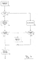
- the flowchart of this first method can be seen in FIG. 4. Some variables are used within the algorithm, which are briefly introduced here in advance.
- the predictive value for RSSI (T) is managed in PRED.
- REQUEST (T) TRUE.
- To check a successful one ANT WE is used to change the antenna.
- DIFF is also used to check whether the RSSI value has dropped significantly after changing the antenna.
- the last RSSI value of one antenna is saved in LAST before switching to another.
- RSSI (T) is added to the n past RSSI values. This means that RSSI (T) is written in the delay chain of the linear predictor. With the following call, the prediction value for RSSI (T + 1) can be calculated.
- ANT-WE is first reduced by one (S2 1). It is then checked in step 22 whether the difference between RS SI (T) and the last RSSI value before the antenna change (LAST) is greater than DIFF. If this is the case, an antenna change is requested via REQUEST (T) (step 15). In this way it is ensured that after an antenna change the reception signal of the 'new' antenna is not clear has a lower signal level than that of the previous one.
- RSSI (T) is adopted in the delay chain of the predictor in step 16 and finally step 6 of the global flow chart is called.
- the difference between the predicted value and the measured RSSI value is not used for decision-making. Instead, a predicted value for RSSI (T + 1) is determined from the current RSSI value (RSSI (T) and a check is carried out to determine whether this value is significantly below the maximum RSSI value of the current antenna to date.
- the algorithm is shown in FIG. 5 described.
- ANT - WE The maximum RSSI value of the antenna currently in use is stored in MAX.
- LIMIT specifies the permissible difference between the prediction value for the next slot and the maximum RSSI value to date.
- REQUEST (T) is first set to FALSE (step 31). It is then checked in step 32 whether ANT-WE is 0. If this is the case, ANT WE is reduced by one (S41) and then in step 42 the difference between RSSI (T) and the last RSSI value of the 'old' antenna is formed. If this difference is greater than DIFF, REQUEST (T) is set to TRUE in step 35 - thus an antenna change is requested.
- step 32 the prediction value PRED is determined using the linear predictor (S33). It is then determined in step 34 whether the value of PRED predicts a significant deterioration (PRED ⁇ MAX-LIMIT?). If this is the case, step 35 is called and REQUEST (T) is set to TRUE.
- step 36 RSSI (T) is compared with MAX for both ways just described, and if RSSI (T) is greater than the previous maximum value, the process branches to step 37 and sets MAX to RSSI (T). Then in step 38 RSSI (T) is added to the past RSSI values.
- step 6 of the global flow diagram is called.
- the predictor for n cycles after an antenna change cannot be used, since the RSSI values of the 'old' antenna first have to be pushed out of the delay chain.
Applications Claiming Priority (4)
| Application Number | Priority Date | Filing Date | Title |
|---|---|---|---|
| DE19525630 | 1995-07-17 | ||
| DE19525630 | 1995-07-17 | ||
| DE19530021 | 1995-08-16 | ||
| DE19530021A DE19530021C2 (de) | 1995-07-17 | 1995-08-16 | Verfahren und Vorrichtung zur Steuerung von Antennen |
Publications (2)
| Publication Number | Publication Date |
|---|---|
| EP0755131A2 true EP0755131A2 (fr) | 1997-01-22 |
| EP0755131A3 EP0755131A3 (fr) | 1999-05-06 |
Family
ID=26016808
Family Applications (1)
| Application Number | Title | Priority Date | Filing Date |
|---|---|---|---|
| EP96109723A Withdrawn EP0755131A3 (fr) | 1995-07-17 | 1996-06-18 | Dispositif de commande d'antenne |
Country Status (1)
| Country | Link |
|---|---|
| EP (1) | EP0755131A3 (fr) |
Cited By (10)
| Publication number | Priority date | Publication date | Assignee | Title |
|---|---|---|---|---|
| WO1999034534A1 (fr) * | 1997-12-30 | 1999-07-08 | Ericsson, Inc. | Systeme unifie de commutation en diversite d'une antenne pour telephones bases sur l'amrt |
| WO1999034535A1 (fr) * | 1997-12-30 | 1999-07-08 | Ericsson, Inc. | Systeme ameliore de commutation d'antenne en diversite pour telephones amrt |
| WO1999034533A1 (fr) * | 1997-12-30 | 1999-07-08 | Ericsson, Inc. | Systeme perfectionne de selection d'antenne |
| FR2780584A1 (fr) * | 1998-06-29 | 1999-12-31 | Canon Kk | Dispositif et procede de selection d'antenne pour une station de communication |
| EP1020055A1 (fr) * | 1997-09-22 | 2000-07-19 | Intel Corporation | Reseau de communication a debit binaire eleve faisant appel a une antenne a balayage sectoriel adaptative |
| WO2001041330A1 (fr) * | 1999-11-30 | 2001-06-07 | Fraunhofer-Gesellschaft zur Förderung der angewandten Forschung e.V. | Emetteur/recepteur dect et procede pour communiquer entre un emetteur/recepteur dect et une station de base dect |
| EP1162762A2 (fr) * | 2000-06-06 | 2001-12-12 | FUBA Automotive GmbH | Procédure pour la reception en diversité des signaux de television numériques. |
| US6360088B1 (en) * | 1998-09-23 | 2002-03-19 | Ericsson Inc. | Antenna diversity switching system and method for selecting an antenna through a programmed evaluation |
| WO2003050970A1 (fr) * | 2001-12-13 | 2003-06-19 | Harman/Becker Automotive Systems (Becker Division) Gmbh | Procede de selection d'une des antennes d'un dispositif de reception a diversite d'antenne et dispositif de reception a diversite d'antenne |
| EP2207273A1 (fr) * | 2009-01-09 | 2010-07-14 | AKG Acoustics GmbH | Procédé de réception de données audio numériques |
Citations (4)
| Publication number | Priority date | Publication date | Assignee | Title |
|---|---|---|---|---|
| JPH0338120A (ja) * | 1989-07-04 | 1991-02-19 | Clarion Co Ltd | ダイバーシティfm多重放送受信機 |
| EP0454585A1 (fr) * | 1990-04-27 | 1991-10-30 | Nippon Telegraph And Telephone Corporation | Sélection d'antenne pour un système de réception diversity |
| DE4236134A1 (de) * | 1992-10-26 | 1994-06-30 | Siemens Ag | Verfahren und Anordnung zur Aktivierung einer von zwei Antennen einer Empfangseinrichtung |
| EP0620657A1 (fr) * | 1993-04-16 | 1994-10-19 | Matsushita Electric Industrial Co., Ltd. | Circuit de commutation d'antenne pour un récepteur en diversité |
-
1996
- 1996-06-18 EP EP96109723A patent/EP0755131A3/fr not_active Withdrawn
Patent Citations (4)
| Publication number | Priority date | Publication date | Assignee | Title |
|---|---|---|---|---|
| JPH0338120A (ja) * | 1989-07-04 | 1991-02-19 | Clarion Co Ltd | ダイバーシティfm多重放送受信機 |
| EP0454585A1 (fr) * | 1990-04-27 | 1991-10-30 | Nippon Telegraph And Telephone Corporation | Sélection d'antenne pour un système de réception diversity |
| DE4236134A1 (de) * | 1992-10-26 | 1994-06-30 | Siemens Ag | Verfahren und Anordnung zur Aktivierung einer von zwei Antennen einer Empfangseinrichtung |
| EP0620657A1 (fr) * | 1993-04-16 | 1994-10-19 | Matsushita Electric Industrial Co., Ltd. | Circuit de commutation d'antenne pour un récepteur en diversité |
Non-Patent Citations (4)
| Title |
|---|
| PATENT ABSTRACTS OF JAPAN vol. 015, no. 170 (E-1062), 30. April 1991 & JP 03 038120 A (CLARION CO LTD), 19. Februar 1991 * |
| PILGER U: "STRUKTUR DES DECT-STANDARDS" NACHRICHTENTECHNIK ELEKTRONIK, BERLIN (DE), Bd. 42, Nr. 1, Januar 1992, Seiten 23-29, XP002016869 * |
| WINTERS J H: "Switched diversity with feedback for DPSK mobile radio systems" IEEE TRANSACTIONS ON VEHICULAR TECHNOLOGY, FEB. 1983, (NEW YORK ) USA, Bd. vt-32, Nr. 1, Seiten 134-150, XP002095641 ISSN 0018-9545 * |
| YASUSHI YAMAO ET AL: "PREDICTIVE ANTENNA SELECTION DIVERSITY (PASD) FOR TDMA MOBILE RADIO" IEICE TRANSACTIONS ON COMMUNICATIONS TOKYO (JP), Bd. E77-B, Nr. 5, 1. Mai 1995, Seiten 641-646, XP000540893 * |
Cited By (15)
| Publication number | Priority date | Publication date | Assignee | Title |
|---|---|---|---|---|
| EP1020055A1 (fr) * | 1997-09-22 | 2000-07-19 | Intel Corporation | Reseau de communication a debit binaire eleve faisant appel a une antenne a balayage sectoriel adaptative |
| EP1020055A4 (fr) * | 1997-09-22 | 2001-12-19 | Intel Corp | Reseau de communication a debit binaire eleve faisant appel a une antenne a balayage sectoriel adaptative |
| WO1999034535A1 (fr) * | 1997-12-30 | 1999-07-08 | Ericsson, Inc. | Systeme ameliore de commutation d'antenne en diversite pour telephones amrt |
| WO1999034533A1 (fr) * | 1997-12-30 | 1999-07-08 | Ericsson, Inc. | Systeme perfectionne de selection d'antenne |
| WO1999034534A1 (fr) * | 1997-12-30 | 1999-07-08 | Ericsson, Inc. | Systeme unifie de commutation en diversite d'une antenne pour telephones bases sur l'amrt |
| FR2780584A1 (fr) * | 1998-06-29 | 1999-12-31 | Canon Kk | Dispositif et procede de selection d'antenne pour une station de communication |
| US6360088B1 (en) * | 1998-09-23 | 2002-03-19 | Ericsson Inc. | Antenna diversity switching system and method for selecting an antenna through a programmed evaluation |
| US6690927B1 (en) | 1999-11-30 | 2004-02-10 | Fraunhofer-Gessellschaft Zur Foerderung Der Angewandten Forschung E.V. | DECT transmit-receive terminal and method for communicating between a DECT transmit-receive terminal and a DECT base station |
| WO2001041330A1 (fr) * | 1999-11-30 | 2001-06-07 | Fraunhofer-Gesellschaft zur Förderung der angewandten Forschung e.V. | Emetteur/recepteur dect et procede pour communiquer entre un emetteur/recepteur dect et une station de base dect |
| EP1162762A2 (fr) * | 2000-06-06 | 2001-12-12 | FUBA Automotive GmbH | Procédure pour la reception en diversité des signaux de television numériques. |
| EP1162762A3 (fr) * | 2000-06-06 | 2004-08-18 | FUBA Automotive GmbH | Procédure pour la reception en diversité des signaux de television numériques. |
| WO2003050970A1 (fr) * | 2001-12-13 | 2003-06-19 | Harman/Becker Automotive Systems (Becker Division) Gmbh | Procede de selection d'une des antennes d'un dispositif de reception a diversite d'antenne et dispositif de reception a diversite d'antenne |
| EP2207273A1 (fr) * | 2009-01-09 | 2010-07-14 | AKG Acoustics GmbH | Procédé de réception de données audio numériques |
| WO2010078605A1 (fr) * | 2009-01-09 | 2010-07-15 | Akg Acoustics Gmbh | Procédé de réception de données audio numériques |
| US8463220B2 (en) | 2009-01-09 | 2013-06-11 | Akg Acoustics Gmbh | System for receiving digital audio data |
Also Published As
| Publication number | Publication date |
|---|---|
| EP0755131A3 (fr) | 1999-05-06 |
Similar Documents
| Publication | Publication Date | Title |
|---|---|---|
| DE69434597T2 (de) | Diversitätsempfänger mit Antennenumschaltung | |
| EP0460748B1 (fr) | Récepteur avec au moins deux branches de réception | |
| DE3211325C1 (de) | System zum automatischen Aufbau einer Kurzwellen-Telegrafiezeichen-Verbindung | |
| DE19983085B3 (de) | Zellenauswahl in Mobilfunksystemen | |
| DE60029006T2 (de) | Verfahren und vorrichtung zum auswählen eines zeitschlitzes in einem tdma-signal | |
| EP2037593A2 (fr) | Installation de diversité d'antennes pour la réception radio à bande relativement large dans des véhicules | |
| DE19833967A1 (de) | Empfangsdiversitätsverfahren und Funk-Kommunikationssystem mit Diversitätsempfang | |
| DE19714967A1 (de) | Diversity-Verfahren, Funkempfänger und Funksystem | |
| EP0496467A2 (fr) | Récepteur pour système de transmission numérique commandé par le facteur de qualité du signal mesuré avec consommation de courant diminuée | |
| EP0755131A2 (fr) | Dispositif de commande d'antenne | |
| EP0330166B1 (fr) | Procédé de commande de puissance d'émission pour la transmission d'informations par voie hertzienne | |
| EP1256191A1 (fr) | Procede de selection d'antennes d'un dispositif de reception dans un system radio, en particulier dans un system de telephonie mobile | |
| EP3504817B1 (fr) | Procédé de sélection de canaux de fréquence | |
| EP0534399B1 (fr) | Procédé de multiplexage temporel pour déterminer la variation de phase d'un signal de réception | |
| WO1994024796A1 (fr) | Procede d'interpolation lineaire permettant d'adapter la reponse impulsionnelle de voie dans des recepteurs pour systemes radiotelephoniques mobiles amrt | |
| EP2245759A1 (fr) | Procédé et dispositif pour recevoir un signal de données avec plusieurs antennes | |
| DE19530021C2 (de) | Verfahren und Vorrichtung zur Steuerung von Antennen | |
| WO1998057441A2 (fr) | Procede et dispositif de reception pour la transmission de donnees | |
| DE102019134540A1 (de) | Verfahren zur Fehlerüberwachung einer Antennenanlage einer Basisstation, Überwachungssystem, Testeinrichtung, Basisstation und Computerprogramm hierzu | |
| DE3725487C2 (de) | Verfahren zum empfangsseitigen Auswerten einer innerhalb eines Rundfunksignals übertragenen digitalen Information | |
| DE10006520A1 (de) | Verfahren zur Schätzung von Kanalparametern von Funkkanälen eines W-CDMA-Mobilfunksystems | |
| DE102004062506A1 (de) | Kommunikationsverfahren und zugehöriges Fahrzeugsicherungssystem | |
| DE10049018B4 (de) | Betriebsverfahren für ein Empfangsgerät | |
| EP0693241A1 (fr) | Detection de donnees a fiabilite commandee dans des recepteurs pour systemes radiotelephoniques mobiles amrt | |
| DE19703060A1 (de) | Verfahren zur Kanalschätzung mit Anpassung eines Kanalmodells während einer Datendetektion |
Legal Events
| Date | Code | Title | Description |
|---|---|---|---|
| PUAI | Public reference made under article 153(3) epc to a published international application that has entered the european phase |
Free format text: ORIGINAL CODE: 0009012 |
|
| AK | Designated contracting states |
Kind code of ref document: A2 Designated state(s): DE ES FR GB IT |
|
| RAP1 | Party data changed (applicant data changed or rights of an application transferred) |
Owner name: HAGENUK GMBH |
|
| RAP1 | Party data changed (applicant data changed or rights of an application transferred) |
Owner name: HAGENUK GMBH |
|
| PUAL | Search report despatched |
Free format text: ORIGINAL CODE: 0009013 |
|
| AK | Designated contracting states |
Kind code of ref document: A3 Designated state(s): DE ES FR GB IT |
|
| 17P | Request for examination filed |
Effective date: 19990812 |
|
| 17Q | First examination report despatched |
Effective date: 20001219 |
|
| RAP1 | Party data changed (applicant data changed or rights of an application transferred) |
Owner name: TELIT MOBILE TERMINALS S.P.A. |
|
| STAA | Information on the status of an ep patent application or granted ep patent |
Free format text: STATUS: THE APPLICATION IS DEEMED TO BE WITHDRAWN |
|
| 18D | Application deemed to be withdrawn |
Effective date: 20021127 |