EP0754901B1 - Dispositifs d'atténuation de bruit, leur fabrication et leur utilisation pour l'atténuation de bruit dans les canalisations - Google Patents
Dispositifs d'atténuation de bruit, leur fabrication et leur utilisation pour l'atténuation de bruit dans les canalisations Download PDFInfo
- Publication number
- EP0754901B1 EP0754901B1 EP19960305363 EP96305363A EP0754901B1 EP 0754901 B1 EP0754901 B1 EP 0754901B1 EP 19960305363 EP19960305363 EP 19960305363 EP 96305363 A EP96305363 A EP 96305363A EP 0754901 B1 EP0754901 B1 EP 0754901B1
- Authority
- EP
- European Patent Office
- Prior art keywords
- duct
- insert
- gas flow
- sound
- section
- Prior art date
- Legal status (The legal status is an assumption and is not a legal conclusion. Google has not performed a legal analysis and makes no representation as to the accuracy of the status listed.)
- Expired - Lifetime
Links
Images


Classifications
-
- F—MECHANICAL ENGINEERING; LIGHTING; HEATING; WEAPONS; BLASTING
- F24—HEATING; RANGES; VENTILATING
- F24F—AIR-CONDITIONING; AIR-HUMIDIFICATION; VENTILATION; USE OF AIR CURRENTS FOR SCREENING
- F24F13/00—Details common to, or for air-conditioning, air-humidification, ventilation or use of air currents for screening
- F24F13/02—Ducting arrangements
- F24F13/0263—Insulation for air ducts
-
- F—MECHANICAL ENGINEERING; LIGHTING; HEATING; WEAPONS; BLASTING
- F16—ENGINEERING ELEMENTS AND UNITS; GENERAL MEASURES FOR PRODUCING AND MAINTAINING EFFECTIVE FUNCTIONING OF MACHINES OR INSTALLATIONS; THERMAL INSULATION IN GENERAL
- F16L—PIPES; JOINTS OR FITTINGS FOR PIPES; SUPPORTS FOR PIPES, CABLES OR PROTECTIVE TUBING; MEANS FOR THERMAL INSULATION IN GENERAL
- F16L55/00—Devices or appurtenances for use in, or in connection with, pipes or pipe systems
- F16L55/02—Energy absorbers; Noise absorbers
- F16L55/033—Noise absorbers
- F16L55/0331—Noise absorbers by inserting an elongated element in the pipe
-
- F—MECHANICAL ENGINEERING; LIGHTING; HEATING; WEAPONS; BLASTING
- F24—HEATING; RANGES; VENTILATING
- F24F—AIR-CONDITIONING; AIR-HUMIDIFICATION; VENTILATION; USE OF AIR CURRENTS FOR SCREENING
- F24F13/00—Details common to, or for air-conditioning, air-humidification, ventilation or use of air currents for screening
- F24F13/24—Means for preventing or suppressing noise
-
- G—PHYSICS
- G10—MUSICAL INSTRUMENTS; ACOUSTICS
- G10K—SOUND-PRODUCING DEVICES; METHODS OR DEVICES FOR PROTECTING AGAINST, OR FOR DAMPING, NOISE OR OTHER ACOUSTIC WAVES IN GENERAL; ACOUSTICS NOT OTHERWISE PROVIDED FOR
- G10K11/00—Methods or devices for transmitting, conducting or directing sound in general; Methods or devices for protecting against, or for damping, noise or other acoustic waves in general
- G10K11/16—Methods or devices for protecting against, or for damping, noise or other acoustic waves in general
- G10K11/161—Methods or devices for protecting against, or for damping, noise or other acoustic waves in general in systems with fluid flow
Definitions
- This application has to do with the construction and implementation of noise attenuation arrangements for gas flow ducts, particularly although not exclusively in air-conditioning and other ventilating systems.
- the accepted method of reducing fan and mechanical noise is to insert a purpose-built attenuator in the ductwork between the fan and the building space being served.
- the ductwork is rectangular or square in section (typically about 1m 2 ) and therefore the attenuators are also normally rectangular or square in section.
- the conventional construction for rectangular or square attenuators is a sheet steel outer case or body of similar sectional shape forming a duct, with a set of parallel rectangular-section acoustic elements or splitters extending at intervals across the duct. Each splitter normally consists of a peripheral sheet steel frame holding a flat infill of absorbent material exposed to the airflow.
- the attenuators are factory manufactured items of considerable complexity which have to be inserted into a break in the ductwork. As the ductwork will vary, many shapes and sizes of attenuator module are needed and manufacture costs are high.
- CH-156689 and DE-A-2620169 disclose acoustic elements - either intersecting plates or open tubular units of square, round or other section - located in symmetrical self-supporting arrays in a duct. These are poor in broad-band noise reduction, however, and tubular units are inconvenient.
- Noise rating curves are well known for many different situations and are normally specified for particular applications; using these data together with knowledge of fan noise levels and natural attenuation losses in the ductwork it is possible to determine the minimum acceptable attenuation required for a given system attenuator. Most conventional attenuators (using a 331/3% free cross-sectional area) reduce higher frequency noise more readily than lower frequency noise. But, for the majority of applications the attenuator design or selection is limited by the low frequency attenuation required (commonly assessed at 125 Hz) leading to more attenuation at middle and higher frequencies than actually required.
- General aims herein include the provision of new and useful attenuator arrangements for ducts, sound-absorptive modules and inserts for use in such arrangements, and methods of providing sound attenuation in ducted systems.
- Each insert comprises or consists essentially of a body of sound-absorbing material having a substantially solid cross-section with peripheral location extremities (apexes and/or extended surfaces of the body) running lengthwise. These location extremities support and align the body in the duct by fitting against the duct casing and/or the peripheries of other insert bodies.
- the insert body also has at least one flat or substantially flat lengthwise attenuation surface which, when the body is aligned in the duct, faces onto the gas flow passage and is inclined to an opposed duct casing surface, preferably at at least 20°.
- the attenuation surface is desirably parallel to the duct's longitudinal axis.
- solid cross-section' I mean that the insert body presents a solid cross-section to flow in the duct. So, the body can actually be solid (free of gross internal cavities) and often this is practical. It may be for example a foam outer cover on a mineral fibre core, or an all-foam body. However the body may have one or more internal openings or cavities provided that no gross internal flow passage is created, i.e the body is functionally non-tubular. One may use for example a tubular form which is blocked e.g. by one or more end-caps and/or intermediate transverse walls.
- At least part of the or each body has at least 100mm solid thickness.
- at least part of the body provides at least 80mm solid thickness (and more preferably at least 100mm) in a direction perpendicular to the attenuation surface.
- Inclining a sound-absorbing surface to the (typically reflective) duct wall enables absorption of sound vibrations in all directions around the propagation axis, as explained in more detail below, while the three-dimensional thickness and solidity of the bodies is easily provided to give good attenuation at lower frequencies.
- One preferred form 6f insert is a solid triangular prism. Any triangular shape can fit in any shape of duct provided that the size is right, but right-angled triangular sections are particularly convenient for manufacture and for rectangular duct casings, the hypotenuse being the attenuation surface and one or both of the other surfaces locating and aligning against the duct walls. However other triangular forms or alignment can be used, e.g. with a single surface engaging the duct wall face-to-face and the only other engagement being at the opposing apex. Two or more triangular inserts can lie side-by-side to occupy rectangular ducts of various widths. For circular ducts, isosceles and particularly equilateral triangular sections are convenient, locating by direct contact of their three body apexes (which may be chamfered) against the duct wall.
- the free area (flow area) in the duct at the attenuator is in the range from 30 to 60%, more preferably 30 to 50% of the duct's cross-section.
- the insert bodies may be formed using any suitable sound-absorptive substance and preferably one with good shape retention.
- Mineral wool or fibre glass may be used, although such bodies usually need to be covered with a facing material to prevent the escape of mineral fibre material.
- a facing material to prevent the escape of mineral fibre material.
- an open-cell foam layer makes an excellent facing material. So, in a further aspect the invention provides a sound absorbing insert according to claim 11.
- the sound absorbing inserts may be based on foam material. Acoustic foam is more expensive than mineral fibre. However I note that for relatively small inserts the extra cost of all-foam is more than offset by the saving in not applying a cover. Furthermore an all-foam insert body has the advantage of greater flexibility, making it particularly suitable for attenuator installation in a duct casing in situ.
- the units may have end plates connected by one or more longitudinal tie bars, to ensure adequate strength or shape retention according to the given requirements. They may indeed be fixed to the duct wall if necessary, e.g by mechanical or adhesive fixing.
- This application also covers methods of making duct noise attenuation assemblies having one or more of the described inserts positioned in a duct.
- ducts of air-conditioning or other ventilation systems Some other proposals concern ways of installing noise attenuation in ducts of air-conditioning or other ventilation systems.
- a typical system has an air-conditioning or ventilation plant connected to a duct system leading to one or more duct openings into the room(s) served by the system: these constitute the terminals of the system.
- the duct system may be branched, with a single primary duct branching into plural secondary ducts.
- a custom-built attenuator device - an expensive arrangement as previously discussed - is installed in the duct system immediately downstream of the plant to absorb the plant's operating noise.
- My attenuator arrangements can be used for that, as described in my earlier application.
- typical duct systems present some extra noise problems and I now propose some ways of addressing them.
- an attenuator can be provided downstream of any control damper or similar control device apt to generate system noise.
- a duct generates noise through turbulence, attenuation can be provided at or near the corresponding terminal opening(s).
- a plant is installed locally e.g. in a ceiling void, attenuation can be provided in its discharge duct and if desired in the intake as well.
- there is "cross-talk" between rooms because of a common duct local attenuation can be installed in this duct.
- the noise attenuation can be provided by putting sound-absorbing duct inserts in the ducts at the appropriate places. This can be done in the existing or standard duct casing, without custom-building an attenuator module, so avoiding considerable labour and expense.
- insert bodies which have good flexibility e.g. all-foam insert bodies
- Such attenuation can be provided even when the duct system is substantially or entirely complete, e.g. as an up-grading of an existing system.
- Such inserts are preferably supported and aligned entirely by their own engagement with the duct walls (and with one another, if more than one), so no special construction or fixing is needed.
- Duct insert product may be made in a range of standard sizes. Standard lengths can easily be adjusted by cutting.
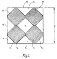
- a square section duct having walls 12 defining a passageway of internal side dimension A has located in it an array of four solid prismatic units 13, each unit being made of acoustic material.
- the array extends over substantially the whole passage area of the duct with spaces 14 between the units of the array and the walls of the duct.
- the array is supported by the walls of the duct and interengagement between the units.
- Each unit is substantially square having four major external surfaces 15, each extending at an angle of 45 degrees to the duct walls and the corners of the modules contacting the walls and each other and the diagonals of the units being parallel to the respective walls of the duct.
- each unit is not exactly square but has its corner edges chamfered to provide minor flat sides 16.
- Ducts tend to be made in a range of standard sizes and the dimension of the module in a direction parallel to the duct wall is preferably a whole number fraction of the dimension A of the duct.
- X as seen in Figure 2 is half of A, therefore for a duct where A equals 600 mm then X would equal 300 mm.
- the dimension Y is then 10 mm, Z is 205 mm and W is 219 mm.
- Modules would be made in a variety of sizes to fit into different standard sizes of duct.
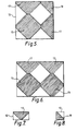
- Figures 5 and 6 show array options including full, half and quarter section modules 13, 17, 18, while Figures 7 and 8 show ducts including only half or quarter section modules 17, 18.
- This arrangement of units in a duct will provide a 50% free area if the modular units are exactly square, 46.72% for the modules in the shape and arrangement as shown and dimensions as indicated above, and a free area of 17% if the modules were regular octagons.
- the free area can be varied by changing the lengths of the major sides and minor sides and generally can be selected by choosing the shape of the module.
- the arrangement of modules as shown can provide an optimum relationship between acoustic material thickness, passage airway and exposed surface area of acoustic material.
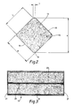
- Figure 3 shows a preferred construction of one unit 13.
- a cylindrical length of acoustic material 20 in the form of mineral fibre (which may be glass fibre) is located between metal end plates 21 connected by an axially extending tie rod 22 to provide stability.
- the cylindrical outer wall is wrapped in a sheet 23 of open cell acoustic foam material which acts as a filter for mineral fibre particles to prevent their escape, but allows penetration of sound waves.
- Figure 4 shows an in situ length of ventilation duct 30 extending between an interior room 31 and the exterior 32 of a building 33.
- a fan 34 is located in the duct to provide a forced airflow through the duct.
- a section of duct 36 corresponding to the duct 12 of Figure 1 contains an array of modular units 13 extending for the length of a single module only, for example 2m, and forming a noise attenuator between the fan 34 and the interior room 31.
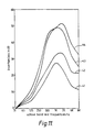
- Figure 9 illustrates the passage of sound waves through a conventional attenuator 24 in a duct section 25 having acoustic splitters 26, and the effect on the sound waves 27, 28 in the horizontal major axis and vertical major axis directions respectively.
- the array of acoustic modules ensures similar attenuation properties in two planes, rather than the single plane effect of the conventional attenuator, and the array ensures the maximum acoustic material thickness for optimum acoustic performance at low frequencies in relationship to the passage airway and free area of the array and enhanced acoustic performance generally throughout the frequency range.
- the core and facing materials for the conventional acoustic splitters and the array modules were the same grade and density of materials, so that the comparison reflects the enhancement in acoustic performance due to my proposals relative to the conventional alternative.
- Figure 11 is a graph of the performance achieved for both arrangements for 1 metre and 2 metre long test sections and clearly shows the benefit of the present array modules.
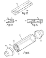
- Figs 12, 13 and 14 show dispositions of foam inserts 118 in rectangular-section duct 12.
- the duct 12 can be part of an existing duct system, not necessarily enlarged in relation to adjacent duct sections.
- the foam inserts 118 have a right-angled triangle cross-section.
- the small angle of the triangle is generally at least about 20° and preferably at least 25°.
- the insert 118 is a single solid piece of any suitable sound-absorbing open-cell foam material e.g. polyethylene or melamine foam.
- a fibre-filled foam sleeve or a hollow foam tube closed against air flow may be used instead.
- the insert section is chosen to extend right across the duct interior, the right-angled surfaces fitting along and up the duct walls and the oblique surface 15 facing onto the flow passage 14 which is 50% of the duct area.
- a set of standard insert sections is made available corresponding to standard duct sizes. For example, widths of 100, 150, 200 and 300mm in combination with any height from that range and also 400mm. Typically lengths are between 0.5 and 2m: standard available lengths might be e.g. 600mm and 1200mm, but of course the same material can easily be length-adjusted, on site if need be, by cutting.
- the small angle of the triangle in this set is preferably between 30° and 45°.
- the inclination of the oblique surface 15 relative to the opposed duct walls ensures that sound vibrations in all directions can be absorbed.
- the use of a solid triangular section presents a substantial thickness of solid material enabling good absorption at the lower frequencies e.g. around 125Hz.
- Fig 14 shows the use of two inserts side by side to fill a larger duct. Many different sizes of duct can be filled to 50% by selecting appropriate members from the available set.
- Fig 15 shows an all-foam insert 119 suitable for use in a circular duct 112.
- the insert 119 has a generally equilateral triangular cross-section presenting three main exterior surfaces 115 for noise attenuation.
- a truly triangular insert would give nearly 60% flow area.
- To adjust flow area to about 50% the longitudinal edges 116 of the insert are chamfered; this also improves frictional engagement against the duct wall.
- Each attenuation surface 115 is inclined relative to all but the exact centre of the opposing section of duct wall. It may be advantageous to enlarge the duct locally and the drawing shows end adaptors 113 for this purpose. However such an insert may also be used in an existing duct without enlargement if the flow characteristics are suitable.
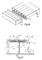
- Fig 16 shows an arrangement of right-angled triangle inserts 118, here with a 45° angle, in a discharge connection duct 212 connected to a fan coil air-conditioning unit whose own discharge duct 110 is shown detached to expose the inserts 118. Because of their flexibility, it will be possible to install the set of inserts 118 even through the angled exhaust of the discharge duct 212 if need be.
- Fig 17 shows a pair of rooms A,B separated by a blockwork wall 152.
- a false (suspended) ceiling 151 is mounted at a spacing below the true ceiling 150.
- a primary air conditioning duct 12 entering through the true ceiling 150 divides into branch ducts 12' with respective openings 99 into the respective rooms A, B.
- the sound insulation provided by the wall 152 is potentially compromised by sound communicating along the branch ducts 12'.
- all-foam duct inserts 118 are pushed into each of the branch ducts as shown. By providing an insert in each branch the arrangement cuts out system noise otherwise propagating from the main duct system 12 into both rooms, as well as preventing noise communication between the rooms.
Landscapes
- Engineering & Computer Science (AREA)
- General Engineering & Computer Science (AREA)
- Mechanical Engineering (AREA)
- Chemical & Material Sciences (AREA)
- Combustion & Propulsion (AREA)
- Physics & Mathematics (AREA)
- Aviation & Aerospace Engineering (AREA)
- Fluid Mechanics (AREA)
- Acoustics & Sound (AREA)
- Multimedia (AREA)
- Duct Arrangements (AREA)
- Soundproofing, Sound Blocking, And Sound Damping (AREA)
Claims (17)
- Dispositif d'atténuation pour atténuer la transmission des bruits dans une canalisation d'écoulement gazeux de section rectangulaire, comprenant un ou plusieurs inserts absorbant le bruit disposés dans la canalisation de sorte qu'au moins un passage d'écoulement gazeux soit défini dans l'arrangement au-delà du ou des inserts, le ou chaque insert consistant essentiellement en un corps solide d'un matériau absorbant le bruit, qui présente sensiblement, une section transversale carrée ou triangulaire pleine et qui est autoporté et aligné dans la canalisation par engagement de ses extrémités longitudinales périphériques contre la paroi de la canalisation et/ou contre les extrémités périphériques d'un ou de plusieurs inserts adjacents, le corps du matériau absorbant le bruit ayant une surface d'atténuation, longitudinale, sensiblement plane, qui forme une paroi du ou d'un passage d'écoulement de gaz et, dans la section transversale, est inclinée dans la canalisation d'un angle situé entre 20 et 70° par rapport à la partie de la paroi de canalisation s'opposant à celle-ci au travers du passage d'écoulement de gaz.
- Dispositif suivant la revendication 1, dans lequel la section transversale du ou de chaque insert est un triangle rectangle dont le plus petit angle a au moins 20°.
- Dispositif suivant la revendication 2, dans lequel le plus petit angle a au moins 25°.
- Dispositif suivant la revendication 2 ou 3, dans lequel les surfaces de l'insert correspondant aux côtés de l'angle droit du triangle sont ajustées contre des parois mutuellement perpendiculaires de la canalisation, la surface d'hypoténuse étant la surface d'atténuation.
- Dispositif suivant l'une quelconque des revendications précédentes, dans lequel un insert unique se trouve entre les parois opposées de la canalisation.
- Dispositif suivant l'une quelconque des revendications 1 à 4, dans lequel plusieurs inserts sont présents sous forme d'une zone autoportée, autoalignée d'inserts qui se trouvent dans la canalisation.
- Dispositif d'atténuation pour atténuer la transmission des bruits dans une canalisation d'écoulement gazeux de section transversale circulaire, comprenant un insert absorbant le bruit disposé dans la canalisation de sorte que des passages d'écoulement gazeux soient définis dans l'arrangement au-delà de l'insert, l'insert consistant essentiellement en un corps d'un matériau absorbant le bruit, de section transversale sensiblement pleine triangulaire, isocèle ou équilatérale, chacune des trois extrémités longitudinales correspondant aux sommets du triangle entrant en contact avec la paroi de la canalisation pour s'aligner et supporter le corps en position dans la canalisation, et les surfaces longitudinales planes du corps procurant des surfaces longitudinales d'atténuation, qui forment les parois internes respectives des trois passages d'écoulement de gaz au-delà du corps dans la canalisation.
- Dispositif suivant l'une quelconque des revendications précédentes, dans lequel les sommets de la section carrée ou triangulaire du corps sont chanfreinés pour procurer des surfaces de contact de faible surface aux extrémités.
- Dispositif suivant l'une quelconque des revendications précédentes, dans lequel la surface de la section du ou des passages d'écoulement de gaz du dispositif d'atténuation compose de 30 à 60% de la surface de section transversale de la canalisation comme un tout dans le dispositif d'atténuation.
- Dispositif suivant l'une quelconque des revendications précédentes, dans lequel le ou chaque corps d'insert consiste essentiellement en une mousse polymérique flexible absorbant le bruit.
- Insert absorbant le bruit pour atténuer la transmission des bruits dans une conduite d'écoulement de gaz, consistant essentiellement en un corps d'un matériau absorbant le bruit, qui est capable d'être autoporté et aligné dans une canalisation par engagement de ses extrémités longitudinales périphériques contre la paroi de la canalisation et/ou contre les extrémités périphériques d'un ou de plusieurs de ces inserts, adjacents, absorbant le bruit, et le corps ayant une surface d'atténuation longitudinale sensiblement plane et dans lequel la section transversale du corps est sensiblement solide et est un carré avec des sommets chanfreinés, un triangle rectangle dont le plus petit angle a au moins 20° ou un triangle isocèle ou équilatéral.
- Insert suivant la revendication 11, dans lequel le corps consiste en un matériau en mousse absorbant le bruit.
- Insert suivant la revendication 11 ou 12, dont la section transversale est un triangle rectangle dont le plus petit angle a au moins 25°.
- Insert suivant l'une quelconque des revendications 11 à 13, dans lequel au moins une partie du corps présente une épaisseur solide d'au moins 80 mm dans une direction perpendiculaire à la surface d'atténuation.
- Procédé pour procurer une atténuation du bruit dans une canalisation d'écoulement de gaz, comprenant un dispositif d'atténuation suivant l'une quelconque des revendications 1 à 10 à un endroit dans la canalisation.
- Procédé suivant la revendication 15, dans lequel la canalisation d'écoulement de gaz fait partie d'un système de conditionnement d'air ou de ventilation dans un bâtiment.
- Procédé suivant la revendication 15 ou 16, dans lequel un corps d'insert tel que défini à la revendication 10 est inséré dans une canalisation d'écoulement de gaz existante, entre une unité de conduite de l'écoulement de gaz et une ouverture dans la canalisation.
Applications Claiming Priority (4)
| Application Number | Priority Date | Filing Date | Title |
|---|---|---|---|
| GBGB9514951.4A GB9514951D0 (en) | 1995-07-21 | 1995-07-21 | Noise attenuators and units of acoustic material |
| GB9514951 | 1995-07-21 | ||
| GBGB9600834.7A GB9600834D0 (en) | 1996-01-16 | 1996-01-16 | Noise attenuation in ducts |
| GB9600834 | 1996-01-16 |
Publications (2)
| Publication Number | Publication Date |
|---|---|
| EP0754901A1 EP0754901A1 (fr) | 1997-01-22 |
| EP0754901B1 true EP0754901B1 (fr) | 2000-02-23 |
Family
ID=26307435
Family Applications (1)
| Application Number | Title | Priority Date | Filing Date |
|---|---|---|---|
| EP19960305363 Expired - Lifetime EP0754901B1 (fr) | 1995-07-21 | 1996-07-22 | Dispositifs d'atténuation de bruit, leur fabrication et leur utilisation pour l'atténuation de bruit dans les canalisations |
Country Status (2)
| Country | Link |
|---|---|
| EP (1) | EP0754901B1 (fr) |
| DE (1) | DE69606742T2 (fr) |
Families Citing this family (4)
| Publication number | Priority date | Publication date | Assignee | Title |
|---|---|---|---|---|
| EP1913242B1 (fr) | 2005-08-08 | 2008-10-29 | Alstom Technology Ltd | Silencieux pour installations de turbines a gaz |
| ITPR20060030A1 (it) * | 2006-04-04 | 2007-10-05 | Gianluca Menozzi | Dispositivo di insonorizzazione e procedimento per realizzarlo. |
| DE102009016609A1 (de) * | 2009-04-08 | 2010-01-21 | Christian Eger | Klimaanlage sowie Schalldämpfmittel für eine Klimanalage |
| ITMI20120925A1 (it) * | 2012-05-28 | 2013-11-29 | Tecnasfalti S R L | Silenziatore acustico di prese d'aria |
Family Cites Families (7)
| Publication number | Priority date | Publication date | Assignee | Title |
|---|---|---|---|---|
| DE523150C (de) | 1930-02-08 | 1931-04-20 | Albert Klein Dr Ing | Vorrichtung zur Schalldaempfung in Leitungen |
| CH203906A (de) * | 1938-04-23 | 1939-04-15 | Oederlin Cie Ag | Geräuschdämpfer für Flüssigkeitsströmungen. |
| GB746949A (en) * | 1952-12-05 | 1956-03-21 | S T Taylor & Sons Ltd | Improvements in acoustic absorbers |
| DE2620169A1 (de) | 1976-05-07 | 1977-11-10 | Gruenzweig Hartmann Glasfaser | Schalldaempfer fuer rohrleitungen |
| SE8006664L (sv) * | 1980-09-24 | 1982-03-25 | Atlas Copco Ab | Ljuddempningsanordning |
| DE3335210A1 (de) * | 1983-09-29 | 1985-04-18 | Messerschmitt-Bölkow-Blohm GmbH, 8012 Ottobrunn | Einrichtung zur daempfung von schall |
| SE447413B (sv) * | 1984-12-11 | 1986-11-10 | Viak Ab | Ljuddempare for reducering av kanalburet luftljud |
-
1996
- 1996-07-22 EP EP19960305363 patent/EP0754901B1/fr not_active Expired - Lifetime
- 1996-07-22 DE DE1996606742 patent/DE69606742T2/de not_active Expired - Fee Related
Also Published As
| Publication number | Publication date |
|---|---|
| DE69606742D1 (de) | 2000-03-30 |
| DE69606742T2 (de) | 2000-10-05 |
| EP0754901A1 (fr) | 1997-01-22 |
Similar Documents
| Publication | Publication Date | Title |
|---|---|---|
| EP0649486B1 (fr) | Chambre sourde et elements structurels anechoiques | |
| AU704038B2 (en) | Sound attenuation assembly for air-cooling apparatus | |
| US6640926B2 (en) | Elbow silencer | |
| EP1131502B1 (fr) | Dispositif d'attenuation de bruit | |
| JP7042579B2 (ja) | 遮音ルーバー | |
| US10260772B2 (en) | Duct mounted sound attenuating baffle with an internally suspended mass layer | |
| US8714304B2 (en) | Soundproofing plate and soundproofing device permitting air flow | |
| KR100468296B1 (ko) | 방음패널 및 그를 위한 다공판 | |
| EP0754901B1 (fr) | Dispositifs d'atténuation de bruit, leur fabrication et leur utilisation pour l'atténuation de bruit dans les canalisations | |
| US4572327A (en) | Sound attenuator | |
| KR102195355B1 (ko) | 가설 방음판 | |
| KR100555375B1 (ko) | 공명형 덕트 소음기 | |
| JP7344665B2 (ja) | 換気用開口構造 | |
| CN210443263U (zh) | 消声装置 | |
| JPS608232Y2 (ja) | 消音装置 | |
| CN111332413A (zh) | 一种船舶舱室防火回风消音装置 | |
| EP4311892A1 (fr) | Une plaque d'amortissement et d'absorption acoustique en matériau fibreux et un silencieux acoustique en cette plaque | |
| JP3044736B2 (ja) | 空調ダクト騒音減衰装置 | |
| JP3755442B2 (ja) | 際根太構造体および床構造体 | |
| JPH0260944B2 (fr) | ||
| EP3746721A1 (fr) | Évent d'aération | |
| CN220290453U (zh) | 消声器 | |
| WO2020042628A1 (fr) | Silencieux de diffusion, silencieux de résonance de diffusion, silencieux de diffusion à spectre complet, système d'assourdissement de canal de ventilation et procédé d'assourdissement associé | |
| FI77101C (fi) | Ljuddaempad anordning, foeretraedesvis vaedringsdon. | |
| DK165564B (da) | Lyddaemper navnlig til ventilationskanaler |
Legal Events
| Date | Code | Title | Description |
|---|---|---|---|
| PUAI | Public reference made under article 153(3) epc to a published international application that has entered the european phase |
Free format text: ORIGINAL CODE: 0009012 |
|
| AK | Designated contracting states |
Kind code of ref document: A1 Designated state(s): BE CH DE DK ES FR GB IE IT LI NL PT SE |
|
| 17P | Request for examination filed |
Effective date: 19970714 |
|
| 17Q | First examination report despatched |
Effective date: 19971217 |
|
| GRAG | Despatch of communication of intention to grant |
Free format text: ORIGINAL CODE: EPIDOS AGRA |
|
| GRAG | Despatch of communication of intention to grant |
Free format text: ORIGINAL CODE: EPIDOS AGRA |
|
| GRAH | Despatch of communication of intention to grant a patent |
Free format text: ORIGINAL CODE: EPIDOS IGRA |
|
| GRAH | Despatch of communication of intention to grant a patent |
Free format text: ORIGINAL CODE: EPIDOS IGRA |
|
| GRAA | (expected) grant |
Free format text: ORIGINAL CODE: 0009210 |
|
| RAP1 | Party data changed (applicant data changed or rights of an application transferred) |
Owner name: GLADDEN, ROBERT ALAN |
|
| RIN1 | Information on inventor provided before grant (corrected) |
Inventor name: GLADDEN, ROBERT ALAN |
|
| AK | Designated contracting states |
Kind code of ref document: B1 Designated state(s): BE CH DE DK ES FR GB IE IT LI NL PT SE |
|
| PG25 | Lapsed in a contracting state [announced via postgrant information from national office to epo] |
Ref country code: ES Free format text: THE PATENT HAS BEEN ANNULLED BY A DECISION OF A NATIONAL AUTHORITY Effective date: 20000223 |
|
| REG | Reference to a national code |
Ref country code: CH Ref legal event code: EP |
|
| REF | Corresponds to: |
Ref document number: 69606742 Country of ref document: DE Date of ref document: 20000330 |
|
| REG | Reference to a national code |
Ref country code: IE Ref legal event code: FG4D |
|
| ITF | It: translation for a ep patent filed |
Owner name: MODIANO & ASSOCIATI S.R.L. |
|
| PG25 | Lapsed in a contracting state [announced via postgrant information from national office to epo] |
Ref country code: SE Free format text: LAPSE BECAUSE OF FAILURE TO SUBMIT A TRANSLATION OF THE DESCRIPTION OR TO PAY THE FEE WITHIN THE PRESCRIBED TIME-LIMIT Effective date: 20000523 Ref country code: PT Free format text: LAPSE BECAUSE OF FAILURE TO SUBMIT A TRANSLATION OF THE DESCRIPTION OR TO PAY THE FEE WITHIN THE PRESCRIBED TIME-LIMIT Effective date: 20000523 Ref country code: DK Free format text: LAPSE BECAUSE OF FAILURE TO SUBMIT A TRANSLATION OF THE DESCRIPTION OR TO PAY THE FEE WITHIN THE PRESCRIBED TIME-LIMIT Effective date: 20000523 |
|
| ET | Fr: translation filed | ||
| PLBE | No opposition filed within time limit |
Free format text: ORIGINAL CODE: 0009261 |
|
| STAA | Information on the status of an ep patent application or granted ep patent |
Free format text: STATUS: NO OPPOSITION FILED WITHIN TIME LIMIT |
|
| 26N | No opposition filed | ||
| PGFP | Annual fee paid to national office [announced via postgrant information from national office to epo] |
Ref country code: FR Payment date: 20010717 Year of fee payment: 6 |
|
| PGFP | Annual fee paid to national office [announced via postgrant information from national office to epo] |
Ref country code: DE Payment date: 20010721 Year of fee payment: 6 |
|
| PGFP | Annual fee paid to national office [announced via postgrant information from national office to epo] |
Ref country code: CH Payment date: 20010723 Year of fee payment: 6 |
|
| PGFP | Annual fee paid to national office [announced via postgrant information from national office to epo] |
Ref country code: NL Payment date: 20010724 Year of fee payment: 6 |
|
| PGFP | Annual fee paid to national office [announced via postgrant information from national office to epo] |
Ref country code: BE Payment date: 20010808 Year of fee payment: 6 |
|
| PGFP | Annual fee paid to national office [announced via postgrant information from national office to epo] |
Ref country code: IE Payment date: 20010816 Year of fee payment: 6 |
|
| REG | Reference to a national code |
Ref country code: GB Ref legal event code: IF02 |
|
| PG25 | Lapsed in a contracting state [announced via postgrant information from national office to epo] |
Ref country code: IE Free format text: LAPSE BECAUSE OF NON-PAYMENT OF DUE FEES Effective date: 20020722 |
|
| PG25 | Lapsed in a contracting state [announced via postgrant information from national office to epo] |
Ref country code: LI Free format text: LAPSE BECAUSE OF NON-PAYMENT OF DUE FEES Effective date: 20020731 Ref country code: CH Free format text: LAPSE BECAUSE OF NON-PAYMENT OF DUE FEES Effective date: 20020731 Ref country code: BE Free format text: LAPSE BECAUSE OF NON-PAYMENT OF DUE FEES Effective date: 20020731 |
|
| BERE | Be: lapsed |
Owner name: *GLADDEN ROBERT ALAN Effective date: 20020731 |
|
| PG25 | Lapsed in a contracting state [announced via postgrant information from national office to epo] |
Ref country code: NL Free format text: LAPSE BECAUSE OF NON-PAYMENT OF DUE FEES Effective date: 20030201 Ref country code: DE Free format text: LAPSE BECAUSE OF NON-PAYMENT OF DUE FEES Effective date: 20030201 |
|
| REG | Reference to a national code |
Ref country code: CH Ref legal event code: PL |
|
| PG25 | Lapsed in a contracting state [announced via postgrant information from national office to epo] |
Ref country code: FR Free format text: LAPSE BECAUSE OF NON-PAYMENT OF DUE FEES Effective date: 20030331 |
|
| NLV4 | Nl: lapsed or anulled due to non-payment of the annual fee |
Effective date: 20030201 |
|
| REG | Reference to a national code |
Ref country code: FR Ref legal event code: ST |
|
| REG | Reference to a national code |
Ref country code: IE Ref legal event code: MM4A |
|
| PG25 | Lapsed in a contracting state [announced via postgrant information from national office to epo] |
Ref country code: IT Free format text: LAPSE BECAUSE OF NON-PAYMENT OF DUE FEES Effective date: 20050722 |
|
| PGFP | Annual fee paid to national office [announced via postgrant information from national office to epo] |
Ref country code: GB Payment date: 20130516 Year of fee payment: 18 |
|
| GBPC | Gb: european patent ceased through non-payment of renewal fee |
Effective date: 20140722 |
|
| PG25 | Lapsed in a contracting state [announced via postgrant information from national office to epo] |
Ref country code: GB Free format text: LAPSE BECAUSE OF NON-PAYMENT OF DUE FEES Effective date: 20140722 |