EP0754591B1 - Siège de véhicule automobile - Google Patents
Siège de véhicule automobile Download PDFInfo
- Publication number
- EP0754591B1 EP0754591B1 EP96830227A EP96830227A EP0754591B1 EP 0754591 B1 EP0754591 B1 EP 0754591B1 EP 96830227 A EP96830227 A EP 96830227A EP 96830227 A EP96830227 A EP 96830227A EP 0754591 B1 EP0754591 B1 EP 0754591B1
- Authority
- EP
- European Patent Office
- Prior art keywords
- seat according
- backrest
- supporting structure
- cable
- frame
- Prior art date
- Legal status (The legal status is an assumption and is not a legal conclusion. Google has not performed a legal analysis and makes no representation as to the accuracy of the status listed.)
- Expired - Lifetime
Links
- 230000007246 mechanism Effects 0.000 claims description 12
- 230000008878 coupling Effects 0.000 claims description 10
- 238000010168 coupling process Methods 0.000 claims description 10
- 238000005859 coupling reaction Methods 0.000 claims description 10
- 230000009471 action Effects 0.000 claims description 5
- 229910001234 light alloy Inorganic materials 0.000 claims description 4
- 239000000725 suspension Substances 0.000 claims description 4
- 238000006073 displacement reaction Methods 0.000 description 6
- 239000000463 material Substances 0.000 description 6
- 230000008901 benefit Effects 0.000 description 4
- 239000004753 textile Substances 0.000 description 2
- 229910000861 Mg alloy Inorganic materials 0.000 description 1
- 230000006978 adaptation Effects 0.000 description 1
- 238000010276 construction Methods 0.000 description 1
- 230000003247 decreasing effect Effects 0.000 description 1
- 238000004519 manufacturing process Methods 0.000 description 1
- 238000004064 recycling Methods 0.000 description 1
- 230000009467 reduction Effects 0.000 description 1
- 238000005728 strengthening Methods 0.000 description 1
- 230000005068 transpiration Effects 0.000 description 1
- 210000000689 upper leg Anatomy 0.000 description 1
Images


Classifications
-
- B—PERFORMING OPERATIONS; TRANSPORTING
- B60—VEHICLES IN GENERAL
- B60N—SEATS SPECIALLY ADAPTED FOR VEHICLES; VEHICLE PASSENGER ACCOMMODATION NOT OTHERWISE PROVIDED FOR
- B60N2/00—Seats specially adapted for vehicles; Arrangement or mounting of seats in vehicles
- B60N2/64—Back-rests or cushions
- B60N2/66—Lumbar supports
- B60N2/667—Lumbar supports having flexible support member bowed by applied forces
- B60N2/6673—Lumbar supports having flexible support member bowed by applied forces with motor driven adjustments
-
- B—PERFORMING OPERATIONS; TRANSPORTING
- B60—VEHICLES IN GENERAL
- B60N—SEATS SPECIALLY ADAPTED FOR VEHICLES; VEHICLE PASSENGER ACCOMMODATION NOT OTHERWISE PROVIDED FOR
- B60N2/00—Seats specially adapted for vehicles; Arrangement or mounting of seats in vehicles
- B60N2/62—Thigh-rests
-
- B—PERFORMING OPERATIONS; TRANSPORTING
- B60—VEHICLES IN GENERAL
- B60N—SEATS SPECIALLY ADAPTED FOR VEHICLES; VEHICLE PASSENGER ACCOMMODATION NOT OTHERWISE PROVIDED FOR
- B60N2/00—Seats specially adapted for vehicles; Arrangement or mounting of seats in vehicles
- B60N2/64—Back-rests or cushions
- B60N2/66—Lumbar supports
- B60N2/667—Lumbar supports having flexible support member bowed by applied forces
- B60N2/6671—Lumbar supports having flexible support member bowed by applied forces with cable actuators
-
- B—PERFORMING OPERATIONS; TRANSPORTING
- B60—VEHICLES IN GENERAL
- B60N—SEATS SPECIALLY ADAPTED FOR VEHICLES; VEHICLE PASSENGER ACCOMMODATION NOT OTHERWISE PROVIDED FOR
- B60N2/00—Seats specially adapted for vehicles; Arrangement or mounting of seats in vehicles
- B60N2/68—Seat frames
- B60N2/686—Panel like structures
-
- B—PERFORMING OPERATIONS; TRANSPORTING
- B60—VEHICLES IN GENERAL
- B60N—SEATS SPECIALLY ADAPTED FOR VEHICLES; VEHICLE PASSENGER ACCOMMODATION NOT OTHERWISE PROVIDED FOR
- B60N2/00—Seats specially adapted for vehicles; Arrangement or mounting of seats in vehicles
- B60N2/80—Head-rests
- B60N2/806—Head-rests movable or adjustable
- B60N2/838—Tiltable
- B60N2/853—Tiltable characterised by their adjusting mechanisms, e.g. electric motors
Definitions
- the present invention relates to motor-vehicle seats.
- an object of the present invention is in particular that of providing a seat having a head-rest which allows adjustment movements which are optimized for the above indicated end, the whole with a relatively simple, reliable and inexpensive structure.
- a motor-vehicle seat comprising:
- the head-rest frame is mounted so as to be rotatable around a first transverse axis onto the backrest supporting structure while being slidable along a substantially vertical direction, and there is provided an auxiliary arm having an upper end pivoted to the lower end of the head-rest frame and a lower end pivoted around a second transverse axis to the backrest supporting structure, said second transverse axis being displaceable along a substantially vertical direction.
- said control means comprise:
- an adjustment system for the head-rest is obtained with simple, reliable and unexpensive means, wherein the head-rest is movable vertically between two end positions to be adapted to the various possible heights of the user, while being rotatable around said first transverse axis, so that the lower edge of the head-rest is moved between a rearwardly fully displaced position and a forwardly fully displaced position.
- This second adjustment movement allows the position of the headrest to be adapted to the position in space of the head of the user, by arranging the head-rest in a position immediately adjacent to the head of the user.
- said headrest frame is slidably and rotatably mounted on said first transverse axis by engagement of a first transverse shaft carried by the backrest supporting structure within at least one guide slot formed in said frame.
- said first flexible cable is directed around said first transverse shaft and has its end opposite to the end connected to said headrest frame which is connected to a device for controlling tensioning of the cable by a lever system which multiplies the cable movement. In this manner, a small linear displacement controlled by said device for controlling the cable tension is transformed in a more extended displacement of the head-rest along the adjustment vertical direction.
- said auxiliary arm carries a second transverse shaft which is slidably and rotatably guided within at least one guide slot formed in the backrest supporting structure, said second cable having one end connected to said frame, a sheath connected to said auxiliary arm and the other end connected to a device for controlling the cable tension.
- the said devices for controlling the cable tension preferably each comprise a screw-and-nut mechanism controlled by either a control knob or an actuating electric motor.
- the backrest supporting structure is preferably comprised of a tray-shaped body, with a cavity facing forwardly, which receives said head-rest at its upper portion.
- said body is comprised of a structure in one piece of light alloy.
- said backrest supporting structure is provided with quick coupling means for mounting thereon of a padding module and said module includes a supporting skeleton and a padding provided with a cover and mounted onto the supporting skeleton.
- Said supporting skeleton includes a flexible arched spine, whose arched configuration is adjustable, and a plurality of substantially rigid transverse ribs adapted to keep the configuration of the padding module substantially constant in a cross-section lying in a horizontal plane, said seat further comprising flexible cable control means to cause arching of said spine.
- the advantage is achieved to allow rapid mounting and dismantling, or replacing, of the backrest padding and on the other hand an optimum adjustment is obtained of the arching of the backrest in order to provide adequate support to the user's back, particularly at the lumbar area.
- the use of the strengthening transverse ribs however keeps the geometry of the backrest substantially constant with respect to a cross section in a horizontal plane, while the degree of arching of the spine of said skeleton of the padding module is varied.
- spring means are interposed between said backrest supporting structure and said padding module.
- these spring means are comprised of a plurality of pairs of helical springs, the springs of each pair being supported in a cantilever fashion by the backrest supporting structure and the padding module, respectively, and being adapted to engage with each other concentrically with a forced fit, so as to form said quick coupling means while fulfilling the function of a suspension for the padding module.
- said springs are preferably each provided with a covering sheath, to prevent jamming between their respective loops in the condition of mutual engagement of the springs of each pair.
- said flexible cable control means for the arching of the skeleton of the padding module comprise a flexible cable arranged so as to tend to move the ends of said spine towards each other when said cable is put under tension. Also in this case there is provided a device for controlling tension of said cable, including a screw-and-nut mechanism controlled either by a control knob or an actuating electric motor.
- said padding module is supported by said backrest supporting structure so as to be movable in a substantially vertical direction with respect to said supporting structure and there are provided spring means to bias the padding module downwardly and flexible cable control means to cause a movement of said module upwardly, against the action of said spring means. In this manner, it is possible to adjust the position of the whole padding module along the vertical direction, in order to adapt it to the various possible configurations of the body of the user.
- a further advantage of the above described arrangement lies in that the conventional body of foamed material constituting the seat padding, connected to said skeleton, may be of a very reduced thickness, so as to favour transpirability of the seat and thus having a greater ability of absorbing transpiration.
- the reduction of the quantity of foamed material used in the padding also provides for a lighter overall unit and poses less problems with respect to disposal or recycling of this foamed material at the end of the life of the seat.
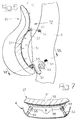
- this cushion has a front portion divided into two separate portions by a middle longitudinal slit, said separate portions being separately adjustable in height by means of two respective control devices.
- each of said portions has a structure which is arched upwardly in its undeformed condition, which can be elastically deflected downwardly by the respective control device which for example is of the flexible cable type.
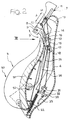
- reference numeral 1 generally designates a motor-vehicle seat, particularly (but not exclusively) for the driving seat, comprising a cushion 2 and a backrest 3 having a supporting structure 4 which, in the illustrated embodiment, is comprised of a body in one piece, preferably of a light alloy, e.g. of a magnesium alloy, shaped as a tray (see figure 4) with a cavity 5 facing forwardly (see again figure 4) which receives the backrest 3 as well as the head-rest 6 at its extreme upper portion.
- a light alloy e.g. of a magnesium alloy
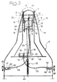
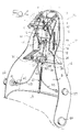
- FIGS. 2, 3 and 4 are a view in a side cross section of the backrest, a front view along arrow III of figure 2 and a perspective view of the supporting structure 4 of the backrest with the supporting mechanism for the head-rest 6, respectively, in these figures, the padding of head-rest 6 is not illustrated, in order to show clearly the supporting frame of head-rest 6, designated by reference numeral 7.
- the head-rest padding is made in any known way of a foamed plastic material, with the associated cover of textile or the like, and is to be anchored to frame 7 also in any known way. It is yet to be noted that the particular configuration of the frame 7 which is shown in the annexed drawings is illustrated purely by way of example, since this configuration may of course be different from what has been illustrated.
- frame 7 comprises two elongated side plates 8 connected to each other by two cross bars 9, 10 and having two longitudinal guide slots 11 wherein there is slidably and rotatably engaged a first transverse shaft 12 whose ends are rigidly connected to two brackets 13 projecting from the bottom wall of the tray-shaped body 4 and are rigidly connected to the latter.
- auxiliary arm 14 which, in the specific example illustrated, comprises two elongated side plates 15 connected to each other by a cross plate 16 and a cross bar 17.
- the ends of plates 15 opposite to those articulated to bar 5 each carries a second transverse shaft 18 which is rotatably and slidably mounted within a longitudinal guide slot 19 formed vertically within the respective bracket 13.
- the frame 7 has the possibility both of pivoting around axis 20 of the first transverse shaft 12, and moving with respective to this axis 20 along the direction of slots 11, which is a substantially vertical direction designated by A in figure 2, the possibility of pivoting around axis 20 being indicated by arrows B in the same figure.
- a rotation of frame 7 around axis 20 is accompanied by a corresponding movement of shafts 18 within the respective guide slots 19 with the resulting rotation of auxiliary arm 14 around the transverse axis 21 of shafts 18.
- Reference numeral 22 designates a helical spring interposed between an inner rib 23 of the supporting structure 4 and one end 24 of a flexible cable 25 whose opposite end is anchored to the cross bar 17 of auxiliary arm 14.
- Spring 22 is able to bias downwardly the cross bar 17 and hence the auxiliary arm 14, thus biassing shafts 18 towards the lower ends of the two respective guide slots 19.
- An upward movement along direction A of figure 2 of frame 7 of the head-rest 6 is controlled, against the action of the return spring 22, by a flexible cable 26 having end 27 anchored to the cross bar 10, directed around transverse shaft 12 and having the opposite end connected at 28 to a lever 29 which is pivotally mounted at 30 to the seat supporting structure 4.
- Lever 29 acts as a system for multiplying displacement, since it is connected at a point 31 which is spaced from articulation axis 30 of a length lower than the distance between axis 30 and the connecting point 28 of cable 26, to one end of a flexible cable 32 provided with a sheath 33 whose end 34 is anchored to an inner rib 35 of body 4.
- the flexible cable 32 may be put under tension by a screw-and-nut mechanism 36, 37 of a type known per se controlled by a control knob 38 arranged on the left side of body 4 or, alternatively, by an actuating electric motor (not shown).
- a rotation of knob 38 causes a corresponding rotation of screw 36 and a resulting axial movement of nut 37 which is connected to the flexible cable 32.
- the cable 32 therefore causes a clockwise rotation (with reference to figure 3) around articulation axis 30 which causes the resulting movement of flexible cable 26 through a distance which is multiplied with respect to the length of the displacement of cable 32.
- This arrangement is particularly advantageous, since the linear displacement which can be provided by a screw-and-nut actuator of the type as device 36, 37 is necessarily reduced, while the adjusting movement of head-rest 6 along direction A must cover a given distance to allow the position of the head-rest to be suited to any height of the user.
- an actuation of knob 38 which causes tensioning of cable 32 causes, as indicated already, a clockwise rotation (with reference to figure 3) of lever 29 and a resulting tensioning of flexible cable 26.
- the latter because it is directed around shaft 12, biasses cross bar 10 upwardly and the whole frame 7 of the head-rest therealong, which can slide upwardly along direction A of figure 2 because of the sliding engagement of slots 11 over the ends of shaft 12.
- the sliding movement of frame 7 along direction A is accompanied by a corresponding rotation of the auxiliary arm 14 around axis 21 and if necessary by a slight vertical movement of shafts 18 within the respective guide slots 19.
- the sliding upwardly of head-rest 6 is carried out against the action of the return spring 22. If one wishes to lower the head-rest, it is possible to obtain an opposite movement by rotating in opposite direction the knob 38 so as to loose cables 32, 26, thus allowing a downward movement of frame 7 as a result of the action of spring 22.
- a forward rotation of frame 7 of the head-rest around the articulation axis 20 may controlled by a second flexible cable 39 associated with a screw-and-nut mechanism 40, 41 of a similar type as the one discussed above, connected to a control knob 42 arranged on the left side of body 4, or alternatively by an actuating electric motor (not shown).
- Cable 39 is provided with a sheath 43 having an end 44 fixed to plate 16 of auxiliary arm 14, whereas the free end of cable 39 is anchored to the cross bar 10, so that a tensioning of cable 39 as a result of an actuation of knob 42 in the corresponding direction tends to move the points at which sheath end 44 and cable end 39 are connected to plate 16 and cross bar 10 respectively to move towards each other.
- a tensioning of cable 39 causes a decrease in the angle defined between frame 7 and auxiliary arm 14 at shaft 9 of mutual articulation.
- This produces an upward movement of shafts 18 within the respective guide slots 19 and a forward tilting movement of the lower portion of frame 7 around the respective articulation axis 20.
- this tilting movement is of course opposed by the return spring 22 which therefore fulfils this function both with respect to the adjustment movement A and the adjustment movement B.
- return spring 22 By rotating knob 42 in an opposite direction, return spring 22 is able to return shafts 18 downwardly, thus rotating rearwardly frame 7 around axis 20.
- head-rest 6 designated by double arrow B in figure 2 allow the lower edge of head-rest to be positioned immediately adjacent to the head of the user even when it is greatly displaced forwardly with respect to the plane of the backrest.
- the backrest 3 of the seat according to the invention has a padding module 50, which can be connected rapidly to the supporting body 4 of the backrest.
- the padding module 50 comprises a padding 51 constituted by a thin mat of foamed plastic material, provided with a covering textile or the like and incorporating a supporting skeleton 52, e.g. constituted of a light alloy, provided with means for quick coupling to body 4.
- a padding 51 constituted by a thin mat of foamed plastic material, provided with a covering textile or the like and incorporating a supporting skeleton 52, e.g. constituted of a light alloy, provided with means for quick coupling to body 4.
- said quick coupling means are comprised of four pairs of helical springs 53, 54, springs 53, 54 of each pair being supported in a cantilever fashion (see in particular figure 9) by skeleton 52 and body 4 respectively and being able to engage within each other coaxially with a forced fit to connect padding module 50 to supporting body 4.
- springs 53, 54 are preferably provided with a cover of plastic material 55, 56, in order to prevent a mutual jamming of the loops of the springs in the engagement condition. Due to the above described arrangement, springs 53, 54 fulfil both the function of quick coupling means for coupling the padding module 50 to the supporting body 4, and the function of elastic suspension means interposed between the padding module 50 and body 4.
- skeleton 52 is provided so as to have a flexible arched spine 57, whose arching is adjustable, extending centrally throughout the vertical extension of skeleton 52.
- the skeleton 52 includes a plurality of transverse ribs 58 which are relatively rigid, which contribute to keep the configuration of skeleton 52, and hence that of padding module 51 with respect to a cross-section lying in a horizontal plane substantially constant.
- the arching of spine 57 may be adjusted by a flexible cable 59 having one end 60 connected to an upper rib 58 of the skeleton and provided with a sheath 61 whose end 62 is fixed to a lower rib 58.
- Cable 59 may be put under tension by a conventional screw-and-nut mechanism controlled by knob 64 (figure 4) arranged on the left side of body 4, in order to increase the arching of spine 57. By rotating knob 64 in an opposite direction, cable 59 is loosened thus allowing skeleton 52 to return towards its undeformed condition, with a minimum arching.
- the above described adjustment movement allows the padding module to be adapted to various configurations of the back of the user, to ensure a proper support particularly in the lumbar area.
- skeleton 52 is for example connected at its lower part to a return spring (like, for example, spring 22 of figure 4) anchored at its opposite end to the body of the backrest, so as to bias downwardly the whole padding module.
- the latter can be moved upwardly by a further flexible cable control device connected to the upper portion of skeleton 52 and arranged so as to bias this skeleton upwardly when the cable is put under tension.
- a further preferred feature of the seat according to the invention lies in that the seat 2 has at its front portion a middle longitudinal slit 70 which defines two separate portions 71, 72, each of which has a flexible supporting structure (not visible in the drawings) which is slightly arched upwardly in its undeformed condition.
- each of the two structures 71, 72 may be deflected downwardly by a respective screw-and-nut control device 73, 74, controlled by a respective knob 75, 76 (or an actuating electric motor) to put a respective control flexible cable 77, 78 under tension.
- This arrangement allows the two portions 71, 72 to be independently adjusted at the various heights, as a function of the support required by the right and left thigh respectively of the user, as a function of the assumed posture, for example during driving.
Landscapes
- Engineering & Computer Science (AREA)
- Aviation & Aerospace Engineering (AREA)
- Transportation (AREA)
- Mechanical Engineering (AREA)
- Seats For Vehicles (AREA)
- Chair Legs, Seat Parts, And Backrests (AREA)
- Automotive Seat Belt Assembly (AREA)
Claims (21)
- Siège de véhicule à moteur, comprenant :un dossier (3) ayant une structure de support (4), etun appuie-tête (6) qui comporte un châssis de support (7) monté sur la structure de support (4) du dossier (3),
caractérisé en ce que le châssis de support (7) de l'appuie-tête (6) est monté sur la structure de support (4) afin qu'il soit mobile le long d'une direction pratiquement verticale (A) et par rotation autour d'un axe transversal (20) par rapport à la structure de support du dossier (4), et en ce que
il existe deux dispositifs séparés de commande à câble souple (26, 39) destinés respectivement à régler les deux déplacements du châssis (7) de l'appuie-tête (6) pour ajuster la position de ce dernier. - Siège selon la revendication 1, caractérisé en ce que le châssis (7) de l'appuie-tête (6) est monté afin qu'il puisse tourner autour d'un premier axe transversal (20) sur la structure de support (4) du dossier (3) tout en pouvant coulisser en direction pratiquement verticale (A),
en ce qu'un bras auxiliaire (14) est incorporé et a une extrémité supérieure qui peut pivoter à l'extrémité inférieure du châssis (7) de l'appuie-tête (6) et une extrémité inférieure qui peut pivoter autour d'un second axe transversal (21) sur la structure de support (4) du dossier, le second axe transversal (21) pouvant coulisser dans une direction sensiblement verticale, et
en ce que le dispositif de réglage comprend :un premier câble souple (26) ayant une première extrémité raccordée au châssis (7) de l'appuie-tête (6) et disposé afin qu'il tire le châssis (7) vers le haut en provoquant un déplacement le long d'une direction pratiquement verticale (A) par rapport à la structure de support (4) du dossier (3), lorsque le premier câble (26) est mis sous tension,un second câble souple (39) disposé entre le châssis (7) et le bras auxiliaire (14) afin qu'il réduise l'angle formé entre le châssis (7) et le bras auxiliaire (14) lorsque le second câble (39) est mis sous tension, etun ressort unique de rappel (22) placé entre la structure de support (4) du dossier (3) et le bras auxiliaire (14) afin qu'il rappelle le second axe transversal (21) vers le bas. - Siège selon la revendication 2, caractérisé en ce que le châssis (7) de l'appuie-tête (6) est monté afin qu'il puisse coulisser et tourner sur le premier axe transversal (20) par coopération d'un premier arbre transversal (12) porté par la structure de support (4) du dossier (3) dans au moins une fente de guidage (11) formée dans le châssis (7).
- Siège selon la revendication 3, caractérisé en ce que le premier câble (26) est dirigé autour du premier arbre transversal (12).
- Siège selon la revendication 4, caractérisé en ce que l'extrémité du premier câble (26) qui est opposée à l'extrémité (27) qui est raccordée au châssis (7) est raccordée à un dispositif (36-38) de réglage de la tension du câble à l'aide d'un système à levier (29) qui multiplie le déplacement du câble.
- Siège selon la revendication 3, caractérisé en ce que le bras auxiliaire (14) porte un second arbre transversal (18) qui est guidé de manière coulissante et rotative à l'intérieur d'au moins une fente de guidage (19) formée dans la structure de support (4) du dossier (3), le second câble (39) ayant une première extrémité raccordée au châssis (7), une gaine (43) raccordée au bras auxiliaire (14) et l'autre extrémité raccordée à un dispositif (40-42) de réglage de la tension du câble.
- Siège selon la revendication 5 ou 6, caractérisé en ce que le dispositif de réglage de la tension d'un câble comprend un mécanisme à vis et écrou (36, 37 ; 40, 41).
- Siège selon la revendication 7, caractérisé en ce que le mécanisme à vis et écrou (36, 37 ; 40, 41) est commandé par un bouton de commande (38 ; 42).
- Siège selon la revendication 8, caractérisé en ce que le mécanisme à vis et écrou (36, 37 ; 40, 41) est commandé par un moteur électrique de manoeuvre.
- Siège selon la revendication 1, caractérisé en ce que la structure de support (4) du dossier (3) comporte un dispositif d'accouplement rapide (53, 54) destiné au montage d'un module de garnissage (50), en ce que le module (50) comprend un squelette de support (52) et un garnissage ayant un organe de couverture monté sur le squelette de support (52), et en ce que le squelette de support (52) comprend une colonne courbe souple (57) dont la courbure est réglable, et plusieurs nervures transversales pratiquement rigides (58) qui peuvent maintenir la configuration du module de garnissage (50) pratiquement constante en coupe dans un plan horizontal, le siège comprenant en outre un dispositif de réglage à câble souple (60-63) destiné à provoquer la courbure de la colonne (57).
- Siège selon la revendication 10, caractérisé en ce qu'un dispositif à ressorts (53, 54) est disposé entre la structure de support (4) du dossier (3) et le module de garnissage (50).
- Siège selon la revendication 11, caractérisé en ce que le dispositif à ressorts comprend plusieurs paires de ressorts hélicoïdaux (53, 54), les ressorts (53, 54) de chaque paire étant supportés en porte-à-faux par la structure de support de dossier (4) et le module de garnissage (50, 52) respectivement et pouvant coopérer concentriquement et par emmanchement forcé de l'un dans l'autre pour former le dispositif d'accouplement rapide tout en remplissant la fonction de suspension du module de garnissage (50).
- Siège selon la revendication 12, caractérisé en ce que les ressorts (53, 54) ont chacun une gaine (55, 56) de recouvrement destinée à empêcher le coincement des boucles respectives à l'état de coopération mutuelle des ressorts (53, 54) de chaque paire.
- Siège selon la revendication 10, caractérisé en ce que le dispositif de réglage à câble souple (60-63) comprend un câble souple (59) disposé afin qu'il déplace les extrémités de la colonne (57) l'une vers l'autre lorsque le câble (59) est mis sous tension.
- Siège selon la revendication 14, caractérisé en ce qu'il comporte un dispositif de réglage destiné à mettre le câble (59) sous tension et comprenant un mécanisme à vis et écrou (63).
- Siège selon la revendication 15, caractérisé en ce que le mécanisme à vis et écrou (63) est commandé par un bouton de commande (64).
- Siège selon la revendication 15, caractérisé en ce que le mécanisme à vis et écrou (63) est commandé par un moteur électrique de manoeuvre.
- Siège selon la revendication 10, caractérisé en ce que le module de garnissage (50) est supporté par la structure de support (4) du dossier (3) afin qu'elle soit mobile en direction pratiquement verticale par rapport à la structure de support (4), et en ce qu'un dispositif à ressorts est destiné à rappeler le module de garnissage (50) vers le bas et un dispositif de réglage à câble souple est destiné à provoquer un déplacement du module vers le haut malgré l'action du dispositif à ressorts.
- Siège selon la revendication 1 ou 10, caractérisé en ce que la structure de support du dossier est constituée d'un corps (4) en forme de plateau ayant une cavité tournée vers l'avant et qui loge le module de garnissage (50) et l'appuie-tête du dossier (3).
- Siège selon la revendication 19, caractérisé en ce que le corps est constitué d'un alliage léger.
- Siège selon la revendication 1, caractérisé en ce qu'il possède un coussin qui, à sa partie avant, a une fente longitudinale médiane qui délimite deux parties avant séparées (71, 72) qui sont souples et légèrement courbées vers le haut à l'état non déformé, ces parties pouvant fléchir vers le bas sous l'action de dispositifs respectifs de réglage à câble souple (77, 78) d'ajustemen séparé de la position en hauteur des parties avant (71, 72) du coussin.
Applications Claiming Priority (2)
| Application Number | Priority Date | Filing Date | Title |
|---|---|---|---|
| IT95TO000619A IT1280437B1 (it) | 1995-07-19 | 1995-07-19 | Sedile di autoveicolo |
| ITTO950619 | 1995-07-19 |
Publications (3)
| Publication Number | Publication Date |
|---|---|
| EP0754591A2 EP0754591A2 (fr) | 1997-01-22 |
| EP0754591A3 EP0754591A3 (fr) | 1997-07-09 |
| EP0754591B1 true EP0754591B1 (fr) | 1998-07-01 |
Family
ID=11413742
Family Applications (1)
| Application Number | Title | Priority Date | Filing Date |
|---|---|---|---|
| EP96830227A Expired - Lifetime EP0754591B1 (fr) | 1995-07-19 | 1996-04-22 | Siège de véhicule automobile |
Country Status (4)
| Country | Link |
|---|---|
| US (1) | US5664841A (fr) |
| EP (1) | EP0754591B1 (fr) |
| DE (1) | DE69600391T2 (fr) |
| IT (1) | IT1280437B1 (fr) |
Families Citing this family (58)
| Publication number | Priority date | Publication date | Assignee | Title |
|---|---|---|---|---|
| DE19603911C2 (de) * | 1996-02-03 | 2000-12-07 | Lear Corp | Klappbare Rückenlehne für Fahrzeugsitze, insbesondere Kraftfahrzeugsitze |
| FR2764563B1 (fr) * | 1997-06-17 | 1999-09-03 | Peugeot | Siege pour vehicule automobile |
| US6189972B1 (en) | 1998-06-05 | 2001-02-20 | Teknion Furniture Systems Inc. | Lumbar support adjustment mechanism |
| EP1159153B1 (fr) | 1998-12-14 | 2005-08-31 | Lear Corporation | Appui-tete pivotant pour vehicules |
| DE19918720B4 (de) * | 1999-04-24 | 2005-09-29 | Keiper Gmbh & Co. Kg | Fahrzeugsitz, insbesondere Kraftfahrzeugsitz |
| US6129421A (en) * | 1999-08-05 | 2000-10-10 | Lear Corporation | Foldable halo style headrest |
| DE19947621B4 (de) | 1999-10-04 | 2011-08-18 | Lear Corp., Mich. | Sitz für ein Fortbewegungsmittel |
| DE29922592U1 (de) * | 1999-12-22 | 2000-04-20 | Breed Automotive Technology, Inc., Lakeland, Fla. | Vorrichtung zum Verstellen einer Kopfstütze an einer Rückenlehne eines Fahrzeugsitzes |
| US6805405B2 (en) * | 2001-03-19 | 2004-10-19 | Sung Yong Co., Ltd. | Chair equipped with lumbar support unit |
| US6565153B2 (en) * | 2001-07-31 | 2003-05-20 | Johnson Controls Technology Corporation | Upper back support for a seat |
| US7000986B2 (en) * | 2001-09-28 | 2006-02-21 | Ficosa North America | Lumbar support apparatus |
| EP1483134B1 (fr) * | 2002-02-12 | 2006-06-28 | Johnson Controls Technology Company | Siege d'automobile a dossier actif |
| CA2626409C (fr) * | 2002-02-13 | 2009-11-24 | Herman Miller, Inc. | Fauteuil basculant a dossier flexible, accoudoirs reglables et profondeur de siege reglable, et leurs procedes d'utilisation |
| US6767064B2 (en) * | 2002-02-27 | 2004-07-27 | Lear Corporation | Translatable head restraint for automotive seat backrest |
| DE10208620C1 (de) * | 2002-02-27 | 2003-07-24 | Itw Automotive Prod Gmbh & Co | Kopfstütze für Automobilsitze |
| US6962392B2 (en) * | 2002-07-24 | 2005-11-08 | O'connor Richard W | Articulated headrest |
| US6893096B2 (en) * | 2002-09-05 | 2005-05-17 | A-Dec, Inc. | Headrest support and adjustment mechanism |
| KR100461147B1 (ko) * | 2002-10-12 | 2004-12-14 | 현대자동차주식회사 | 목 상해 방지용 자동차 시트 |
| US20040080197A1 (en) * | 2002-10-25 | 2004-04-29 | Robert Kopetzky | Transmission amplifier for bowden cables and method of using the same |
| US6789846B2 (en) | 2002-12-20 | 2004-09-14 | Lear Corporation | Vehicle seat having a movable head restraint |
| US7097242B2 (en) * | 2003-02-06 | 2006-08-29 | Lear Corporation | Anti-backdriving active head restraint |
| WO2005110803A1 (fr) * | 2003-07-21 | 2005-11-24 | Intier Automotive Inc. | Traversins lateraux ajustables |
| DE10335268B3 (de) * | 2003-08-01 | 2004-12-23 | Itw Automotive Products Gmbh & Co. Kg | Kopfstütze für den Sitz eines Automobils |
| DE10337881A1 (de) * | 2003-08-18 | 2005-03-24 | Schukra Gerätebau AG | Lordosenstützkorb |
| US6749256B1 (en) | 2003-09-08 | 2004-06-15 | Lear Corporation | Vehicle seat having a movable head restraint |
| ATE475557T1 (de) * | 2003-11-11 | 2010-08-15 | Johnson Controls Tech Co | Mechanismus zum verstellen einer sitzrückenlehne |
| DE202004002569U1 (de) * | 2004-02-19 | 2005-07-07 | Schwarzbich, Jörg | Lordosenstütze |
| EP1781492A4 (fr) * | 2004-08-12 | 2008-11-26 | Intier Automotive Inc | Mecanisme de chassis de coussin de siege reglable |
| FR2875753B1 (fr) * | 2004-09-30 | 2008-08-08 | Faurecia Sieges Automobile | Dispositif de reglage pour siege |
| US7185950B2 (en) | 2004-12-28 | 2007-03-06 | Fisher Dynamics Corporation | Head restraint system |
| US20060138817A1 (en) * | 2004-12-29 | 2006-06-29 | Gorman Patrick J | Energy absorbing seat recliner assembly |
| US8152242B2 (en) * | 2005-04-04 | 2012-04-10 | Lear Corporation | Selective remote head restraint actuation |
| DE102005045045A1 (de) * | 2005-09-21 | 2007-03-29 | Schukra Gerätebau AG | Verstellbare Kopfstütze |
| EP1772130B1 (fr) * | 2005-10-10 | 2010-04-21 | Degonda-Rehab S.A. | Ensemble appui-tête réglable |
| EP2032000A4 (fr) * | 2006-06-16 | 2010-05-26 | Schukra North America Ltd | Mécanisme de déclenchement pour appui-tête |
| DE102007004767A1 (de) * | 2007-01-31 | 2008-08-07 | Bayerische Motoren Werke Aktiengesellschaft | Rückenlehne für einen Fahrzeugsitz mit neigungsverstellbarem Lehnenkopf |
| DE102007006835A1 (de) * | 2007-02-07 | 2008-08-14 | Johnson Controls Gmbh | Aktuierungsmittel für eine crash-aktive Kopfstütze |
| US7992933B2 (en) * | 2007-06-21 | 2011-08-09 | Lear Corporation | Integrated vehicle seat with active head restraint system |
| US8100472B2 (en) * | 2008-03-17 | 2012-01-24 | Lear Corporation | Vehicle active head restraint system with a locking linkage |
| US8025337B2 (en) * | 2008-12-18 | 2011-09-27 | La-Z-Boy Incorporated | Adjustable head rest assembly for furniture member |
| US8197007B2 (en) * | 2009-11-03 | 2012-06-12 | Bae Industries, Inc. | Combination pivotal and displaceable headrest assembly incorporated into a vehicle seat |
| USD637423S1 (en) | 2010-04-13 | 2011-05-10 | Herman Miller, Inc. | Chair |
| USD650206S1 (en) | 2010-04-13 | 2011-12-13 | Herman Miller, Inc. | Chair |
| USD657166S1 (en) | 2010-04-13 | 2012-04-10 | Herman Miller, Inc. | Chair |
| USD639091S1 (en) | 2010-04-13 | 2011-06-07 | Herman Miller, Inc. | Backrest |
| USD653061S1 (en) | 2010-04-13 | 2012-01-31 | Herman Miller, Inc. | Chair |
| US8449037B2 (en) | 2010-04-13 | 2013-05-28 | Herman Miller, Inc. | Seating structure with a contoured flexible backrest |
| USD652657S1 (en) | 2010-04-13 | 2012-01-24 | Herman Miller, Inc. | Chair |
| SE536454C2 (sv) * | 2012-02-06 | 2013-11-12 | Lt Office Line Ab | Kontorsstol med ett justerbart ländryggsstöd |
| DE102012208725A1 (de) | 2012-05-24 | 2013-11-28 | Lufthansa Technik Ag | Rückenlehne für einen Fahrzeugsitz |
| US9409504B2 (en) * | 2013-01-24 | 2016-08-09 | Ford Global Technologies, Llc | Flexible seatback system |
| DE102013102111A1 (de) * | 2013-03-04 | 2014-09-04 | Recaro Aircraft Seating Gmbh & Co. Kg | Flugzeugsitzvorrichtung |
| DE102013225963B4 (de) * | 2013-12-13 | 2023-06-22 | Adient Us Llc | Sitzteil und Fahrzeugsitz |
| DE102014119612A1 (de) * | 2014-12-23 | 2016-06-23 | Recaro Aircraft Seating Gmbh & Co. Kg | Sitzvorrichtung mit längsgeteilter Sitzbodeneinheit |
| US10399474B2 (en) * | 2016-03-02 | 2019-09-03 | Adient Luxembourg Holding S.a.r.l. | Multi-adjustable head restraint |
| US10493882B1 (en) * | 2018-05-29 | 2019-12-03 | Ford Global Technologies, Llc | Vehicle seatback with thoracic support actuated pillow |
| JP7127557B2 (ja) * | 2019-01-24 | 2022-08-30 | トヨタ紡織株式会社 | ヘッドレスト |
| GB2620941B (en) * | 2022-07-26 | 2025-02-05 | Jaguar Land Rover Ltd | Head restraint for a vehicle seat |
Family Cites Families (10)
| Publication number | Priority date | Publication date | Assignee | Title |
|---|---|---|---|---|
| US3065029A (en) * | 1960-11-02 | 1962-11-20 | Spound | Headrest construction |
| FR2568528B1 (fr) * | 1984-08-03 | 1988-10-14 | Peugeot Cycles | Appui-tete reglable pour siege d'automobile ou analogue |
| FR2583361B1 (fr) * | 1985-06-12 | 1987-09-04 | Faure Bertrand | Perfectionnements aux appuis-tete reglables et aux sieges equipes de tels appuis-tete |
| JP2545833B2 (ja) * | 1987-02-28 | 1996-10-23 | アイシン精機株式会社 | ヘツドレスト装置 |
| DE3831790A1 (de) * | 1988-09-19 | 1990-03-22 | Bayerische Motoren Werke Ag | Sitz, insbesondere kraftfahrzeugsitz |
| DE3843616A1 (de) * | 1988-12-23 | 1990-06-28 | Bayerische Motoren Werke Ag | Sitz, insbesondere kraftfahrzeugsitz |
| AT394829B (de) * | 1989-08-04 | 1992-06-25 | Schuster Wilhelm | Rueckenlehne fuer einen fahrzeugsitz, mit einer verstellbaren lendenstuetze |
| DE4031656A1 (de) * | 1990-10-05 | 1992-04-09 | Ameu Management Corp | Vorrichtung zur verstellung, insbesondere zur hoehenverstellung, einer kopfstuetze |
| US5217278A (en) * | 1991-03-13 | 1993-06-08 | Findlay Industries, Inc. | Mechanism for providing adjustable lumbar support in a seat |
| US5464269A (en) * | 1993-10-12 | 1995-11-07 | Mizelle; Ned W. | Upholstered furniture and movable headrest |
-
1995
- 1995-07-19 IT IT95TO000619A patent/IT1280437B1/it active IP Right Grant
-
1996
- 1996-04-22 DE DE69600391T patent/DE69600391T2/de not_active Expired - Lifetime
- 1996-04-22 EP EP96830227A patent/EP0754591B1/fr not_active Expired - Lifetime
- 1996-04-30 US US08/641,034 patent/US5664841A/en not_active Expired - Fee Related
Also Published As
| Publication number | Publication date |
|---|---|
| ITTO950619A1 (it) | 1997-01-19 |
| DE69600391D1 (de) | 1998-08-06 |
| ITTO950619A0 (it) | 1995-07-19 |
| EP0754591A3 (fr) | 1997-07-09 |
| IT1280437B1 (it) | 1998-01-20 |
| EP0754591A2 (fr) | 1997-01-22 |
| DE69600391T2 (de) | 1999-04-08 |
| US5664841A (en) | 1997-09-09 |
Similar Documents
| Publication | Publication Date | Title |
|---|---|---|
| EP0754591B1 (fr) | Siège de véhicule automobile | |
| EP0754590A2 (fr) | Siège de véhicule automobile | |
| US6099076A (en) | Chair back construction | |
| US8454090B2 (en) | Pelvic and lumbar support system | |
| US5120109A (en) | Motor vehicle seat | |
| JP2020054882A (ja) | 椅子アセンブリ | |
| CA2740958C (fr) | Systeme de soutien lombaire pour element de meuble | |
| US20070080570A1 (en) | Vehicle seat with a deformable backrest | |
| CA2740966C (fr) | Ensemble appui-tete reglable pour element de meuble | |
| GB2277021A (en) | A height adjustable automotive vehicle seat | |
| US4880272A (en) | Seat furniture | |
| EP0173511A2 (fr) | Sièges de véhicules | |
| US4682763A (en) | Flexible mounting | |
| CA2740961C (fr) | Support lombaire et mecanisme d'ajustement d'appui-tete | |
| EP1849651B1 (fr) | Siège pour machines de terrassement ou similaires | |
| EP0232687B1 (fr) | Siège réglable pour véhicules automobiles | |
| KR102522891B1 (ko) | 시트용 암레스트의 높이 조절장치 | |
| WO2024214779A1 (fr) | Siège | |
| JP2024152546A (ja) | シート | |
| KR960004710Y1 (ko) | 자동차용 좌석 등받이의 맛사지 구동장치 |
Legal Events
| Date | Code | Title | Description |
|---|---|---|---|
| PUAI | Public reference made under article 153(3) epc to a published international application that has entered the european phase |
Free format text: ORIGINAL CODE: 0009012 |
|
| AK | Designated contracting states |
Kind code of ref document: A2 Designated state(s): DE FR GB IT |
|
| PUAL | Search report despatched |
Free format text: ORIGINAL CODE: 0009013 |
|
| AK | Designated contracting states |
Kind code of ref document: A3 Designated state(s): DE FR GB IT |
|
| 17P | Request for examination filed |
Effective date: 19970821 |
|
| GRAG | Despatch of communication of intention to grant |
Free format text: ORIGINAL CODE: EPIDOS AGRA |
|
| GRAG | Despatch of communication of intention to grant |
Free format text: ORIGINAL CODE: EPIDOS AGRA |
|
| GRAH | Despatch of communication of intention to grant a patent |
Free format text: ORIGINAL CODE: EPIDOS IGRA |
|
| 17Q | First examination report despatched |
Effective date: 19971127 |
|
| GRAH | Despatch of communication of intention to grant a patent |
Free format text: ORIGINAL CODE: EPIDOS IGRA |
|
| GRAA | (expected) grant |
Free format text: ORIGINAL CODE: 0009210 |
|
| AK | Designated contracting states |
Kind code of ref document: B1 Designated state(s): DE FR GB IT |
|
| ITF | It: translation for a ep patent filed | ||
| REF | Corresponds to: |
Ref document number: 69600391 Country of ref document: DE Date of ref document: 19980806 |
|
| ET | Fr: translation filed | ||
| PLBE | No opposition filed within time limit |
Free format text: ORIGINAL CODE: 0009261 |
|
| STAA | Information on the status of an ep patent application or granted ep patent |
Free format text: STATUS: NO OPPOSITION FILED WITHIN TIME LIMIT |
|
| 26N | No opposition filed | ||
| PGFP | Annual fee paid to national office [announced via postgrant information from national office to epo] |
Ref country code: FR Payment date: 20000330 Year of fee payment: 5 |
|
| PGFP | Annual fee paid to national office [announced via postgrant information from national office to epo] |
Ref country code: GB Payment date: 20000403 Year of fee payment: 5 |
|
| PG25 | Lapsed in a contracting state [announced via postgrant information from national office to epo] |
Ref country code: GB Free format text: LAPSE BECAUSE OF NON-PAYMENT OF DUE FEES Effective date: 20010422 |
|
| PG25 | Lapsed in a contracting state [announced via postgrant information from national office to epo] |
Ref country code: FR Free format text: THE PATENT HAS BEEN ANNULLED BY A DECISION OF A NATIONAL AUTHORITY Effective date: 20010430 |
|
| GBPC | Gb: european patent ceased through non-payment of renewal fee |
Effective date: 20010422 |
|
| REG | Reference to a national code |
Ref country code: FR Ref legal event code: ST |
|
| PG25 | Lapsed in a contracting state [announced via postgrant information from national office to epo] |
Ref country code: IT Free format text: LAPSE BECAUSE OF NON-PAYMENT OF DUE FEES;WARNING: LAPSES OF ITALIAN PATENTS WITH EFFECTIVE DATE BEFORE 2007 MAY HAVE OCCURRED AT ANY TIME BEFORE 2007. THE CORRECT EFFECTIVE DATE MAY BE DIFFERENT FROM THE ONE RECORDED. Effective date: 20050422 |
|
| PGFP | Annual fee paid to national office [announced via postgrant information from national office to epo] |
Ref country code: DE Payment date: 20100428 Year of fee payment: 15 |
|
| REG | Reference to a national code |
Ref country code: DE Ref legal event code: R119 Ref document number: 69600391 Country of ref document: DE |
|
| REG | Reference to a national code |
Ref country code: DE Ref legal event code: R119 Ref document number: 69600391 Country of ref document: DE |
|
| PG25 | Lapsed in a contracting state [announced via postgrant information from national office to epo] |
Ref country code: DE Free format text: LAPSE BECAUSE OF NON-PAYMENT OF DUE FEES Effective date: 20111031 |