EP0754548B1 - Lageranordnung für einen Druckmaschinenzylinder - Google Patents
Lageranordnung für einen Druckmaschinenzylinder Download PDFInfo
- Publication number
- EP0754548B1 EP0754548B1 EP96109626A EP96109626A EP0754548B1 EP 0754548 B1 EP0754548 B1 EP 0754548B1 EP 96109626 A EP96109626 A EP 96109626A EP 96109626 A EP96109626 A EP 96109626A EP 0754548 B1 EP0754548 B1 EP 0754548B1
- Authority
- EP
- European Patent Office
- Prior art keywords
- bearing
- pressure
- pressure element
- cylinder
- printing press
- Prior art date
- Legal status (The legal status is an assumption and is not a legal conclusion. Google has not performed a legal analysis and makes no representation as to the accuracy of the status listed.)
- Expired - Lifetime
Links
- 238000007639 printing Methods 0.000 title claims description 17
- 230000005684 electric field Effects 0.000 claims description 4
- 238000007645 offset printing Methods 0.000 claims description 3
- 239000012530 fluid Substances 0.000 claims description 2
- 238000005452 bending Methods 0.000 description 5
- 239000000463 material Substances 0.000 description 5
- 238000005096 rolling process Methods 0.000 description 2
- 238000005553 drilling Methods 0.000 description 1
- 230000000694 effects Effects 0.000 description 1
- 238000009434 installation Methods 0.000 description 1
- 239000002184 metal Substances 0.000 description 1
Images


Classifications
-
- B—PERFORMING OPERATIONS; TRANSPORTING
- B41—PRINTING; LINING MACHINES; TYPEWRITERS; STAMPS
- B41F—PRINTING MACHINES OR PRESSES
- B41F13/00—Common details of rotary presses or machines
- B41F13/08—Cylinders
- B41F13/20—Supports for bearings or supports for forme, offset, or impression cylinders
Definitions
- the invention relates to a bearing arrangement for a printing press cylinder, in particular for an offset printing machine with bearings on both sides in a starting and stopping eccentric Cylinder journal.
- DE 2 636 555 C2 discloses a backlash-free cylinder bearing for printing presses which has loading devices for producing a bending bridge which acts on the journal bearing.
- the loading devices are arranged in parallel in the longitudinal bores of the machine wall running parallel to the cylinder axis on both sides at an angle to the resulting bearing force and are thus formed by a metal body as a bending bridge.
- This bending bridge acts in a linear manner on the bearing bush, which leads to so-called "feed eaters” in a known manner.
- a slot which is separate from the machine wall is arranged at the end of the longitudinal bore of the loading device. In this embodiment too, the bending bridge is partially deformed by the linear load of the bearing body.
- the object of the invention is to provide a noticeably reduced bearing arrangement for a printing press cylinder, which ensures the required break resistance without deforming the sliding or rolling bearing.
- the bearing arrangement has at least one pressure element arranged in the region of the bearing bore, preferably an elastic pressure element, which acts on the bearing from a position integrated into the machine frame in a defined circular sector.
- the bearing arrangement can accommodate a plain bearing or a roller bearing in an eccentric bearing.
- a surface force increases the security against breakage in the printing press cylinder bearing.
- the applied surface load acts on the plain bearing or rolling bearing without any dangerous deformation, since the bearing play can be influenced in the form of a surface.
- the bearing arrangement is fixed in position by the surface pressure of the pressurized pressure element; when the pressure is on or pressure off, the pressure element is depressurized.
- the pressure element can be acted upon pneumatically or with a fluid, for example hydraulically.
- the application can also be carried out using a piezo material.
- the pressure element is preferably elastic, at least in the area that applies a surface pressure to the bearing.
- the bearing arrangement is not limited to a pressure element. Rather, several pressure elements can enclose the bearing arrangement in a sector of a circle.
- a plate cylinder 2 with a blanket cylinder in a printing unit 1 adjacent and the blanket cylinder 1 is with a printing cylinder 3rd arranged adjacent.
- the cylinders 1, 2, 3 have cylinder journals that are in the frame side a bearing 1 'for the blanket cylinder 1, a bearing 2' for the plate cylinder 2 and a bearing 3 'for the printing cylinder 3 are added.
- the bearing 1 'marked with detail X for the blanket cylinder 1 considered as a bearing arrangement.
- the bearing 1 ' represents an eccentric bearing arrangement which houses a bearing bush.
- a pressure element 5 is approximately concentric in a circular sector arranged for storage 1 '.
- the pressure element 5 is in a recess in the machine frame 4 recorded and acts on the storage 1 '.
- the pressure element 5 has a pressure supply / discharge 6
- a sensor can be arranged on the annular gap, which is controlled by a machine control for measuring bearing play, operating temperature, relative movement of the External bearing activates or stops the pressure element 5.
- Pressure element 5 is a crescent-shaped hollow body which is connected to the pressure supply / discharge 6 with a pressure medium source, e.g. a pneumatic device or Hydraulic device, is coupled.
- the hollow body is made of an elastic plastic.
- the pressure element 5 can also be made of a piezoelectric, preferably piezoceramic, Material.
- the pressure element 5 is made use of inverse piezoceramic effect activated.
- the pressure element 5 is in this training Connected to an adjustable voltage source in terms of circuitry an electrical field causes a change in dimension of the piezoelectric material of the pressure element 5.
- an electrical field causes a change in dimension of the piezoelectric material of the pressure element 5.
- the mode of action is as follows: In the bore 7, the bearing 1 'and in this a cylinder journal is used.
- the annular gap between the bore 7 and the bearing 1 ' also extends to the pressure element 5.
- the bearing 1' can be pivoted in the annular gap for the adjusting movement “pressure on” or the parking movement “pressure off” of the blanket cylinder 1.
- the printing element 5 is activated via the machine control.
- the pressure element is in the bearing 1 'in a circular sector of max. 180 ° applied a surface pressure, which fixes the bearing 1 'frictionally during printing.
- the arrangement of the pressure element 5 to the bearing 1 ' is to be carried out in such a way that the resulting force undergoes the smallest possible change in direction (in a defined angular range) during printing operation. This ensures the exact fixation of the bearing 1 'in the bore 7 even in the event of changing external loads.
Landscapes
- Engineering & Computer Science (AREA)
- Mechanical Engineering (AREA)
- Support Of The Bearing (AREA)
- Rotary Presses (AREA)
- Paper (AREA)
Description
Die Lageranordnung besitzt mindestens ein im Bereich der Lagerbohrung angeordnetes Druckelement, vorzugsweise ein elastisches Druckelement, welches von einer in das Maschinengestell integrierten Position ausgehend in einem definierten Kreissektor auf das Lager wirkt. Die Lageranordnung kann dabei ein Gleitlager oder ein Wälzlager in einer Exzenterlagerung aufnehmen. Durch eine flächenförmig aufgebrachte Kraft wird die Bruchsicherheit in der Druckmaschinenzylinderlagerung erhöht. Die aufgebrachte Flächenlast wirkt ohne gefährdende Deformation auf das Gleitlager oder Wälzlager, da flächenförmig das Lagerspiel beeinflußbar ist. Während des Druckbetriebes ist durch den Flächendruck des beaufschlagten Druckelementes die Lageranordnung lagefixiert, bei Druck an- bzw. Druck ab-Stellung ist das Druckelement drucklos. Die Beaufschlagung des Druckelementes kann dabei pneumatisch oder mit einem Fluid,z.B. hydraulisch, erfolgen. In einer weiteren Ausbildung kann die Beaufschlagung auch durch einen Piezowerkstoff erfolgen. Vorzugsweise ist das Druckelement zumindest in dem einen Flächendruck auf die Lagerung aufbringenden Bereich elastisch. Die Lageranordnung ist nicht auf ein Druckelement beschränkt. Vielmehr können auch mehrere Druckelemente die Lageranordnung in je einem Kreissektor umschließen.
- Fig. 1
- eine Druckzylinderanordnung (schematisch),
- Fig. 2
- eine Lageranordnung mit Druckelement.
- Fig. 3
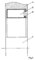
- ein Druckelement in Einbaulage (Schnitt A-A)
In der Bohrung 7 ist die Lagerung 1' und in dieser ein Zylinderzapfen eingesetzt. Der Ringspalt zwischen Bohrung 7 und Lagerung 1' erstreckt sich auch auf das Druckelement 5. Für die Anstellbewegung "Druck an" bzw. Abstellbewegung "Druck ab" des Gummituchzylinders 1 ist die Lagerung 1' in dem Ringspalt schwenkbar. Für den Druckbetrieb wird das Druckelement 5 über die Maschinensteuerung aktiviert. Durch das Druckelement wird am Lager 1' in einem Kreissektor von max. 180° ein Flächendruck aufgebracht, der das Lager 1' reibschlüssig bei Druckbetrieb fixiert. Die Anordnung des Druckelementes 5 zum Lager 1' ist dabei so vorzunehmen, daß die resultierende Kraft im Druckbetrieb eine möglichst geringe (in einem definierten Winkelbereich) Richtungsänderung erfährt. Damit wird auch im Falle wechselnder äußerer Lasten die exakte Fixierung des Lagers 1' in der Bohrung 7 gewährleistet.
- 1
- Gummituchzylinder
- 1'
- Lager
- 2
- Plattenzylinder
- 2'
- Lager
- 3
- Druckzylinder
- 3'
- Lager
- 4
- Maschinengestell
- 5
- Druckelement
- 6
- Druckzuführung/Druckabführung
- 7
- Bohrung
- X
- Detail
Claims (5)
- Lageranordnung für einen Druckmaschinenzylinder, insbesondere für eine Offsetdruckmaschine mit beidseitig in einem An- und Abstellexzenter gelagerten Zylinderzapfen und einem Druckelement mit Mitteln für eine Druckzuführung und Druckabführung,
dadurch gekennzeichnet,
daß in einem eine integrierte Lagerbohrung (7) aufweisenden Maschinengestell (4) mindestens ein Druckelement (5) mit einer Druckzuführung/Druckabführung ortsfest in einem Kreissektor konzentrisch einem Lager (1',2',3') benachbart angeordnet ist, wobei bei Druckbeaufschlagung des Druckelementes (5) das Lager (1',2',3') fixierbar und bei Druckentlastung des Druckelementes (5) das Lager (1',2',3') für eine Schwenkbewegung frei ist. - Lageranordnung nach Anspruch 1,
dadurch gekennzeichnet,
daß das Druckelement (5) ein elastischer Hohlkörper ist, der mit einer Druckmittelquelle gekoppelt ist. - Lageranordnung nach Anspruch 2,
dadurch gekennzeichnet,
daß das Druckelement (5) pneumatisch betätigbar ist. - Lageranordnung nach Anspruch 2,
dadurch gekennzeichnet,
daß das Druckelement (5) mit einem Fluid betätigbar ist. - Lageranordnung für einen Druckmaschinenzylinder, insbesondere für eine Offsetdruckmaschine mit beidseitig in einem An- und Abstellexzenter gelagerten Zylinderzapfen,
dadurch gekennzeichnet,
daß in ein Maschinengestell (4) mit einer Lagerbohrung (7) integriert mindestens ein piezoelektrisches Druckelement (5) schaltungstechnisch mit einer einstellbaren Spannungsquelle verbunden ist und in einem Kreissektor konzentrisch einem Lager (1', 2', 3') benachbart angeordnet ist, welches unter Einwirkung eines elektrischen Feldes das Lager (1', 2', 3') fixiert und bei Wegfall des elektrischen Feldes das Lager (1', 2', 3') für eine Schwenkbewegung frei gibt.
Applications Claiming Priority (2)
| Application Number | Priority Date | Filing Date | Title |
|---|---|---|---|
| DE19526305A DE19526305A1 (de) | 1995-07-19 | 1995-07-19 | Lagerung für einen Druckmaschinenzylinder |
| DE19526305 | 1995-07-19 |
Publications (2)
| Publication Number | Publication Date |
|---|---|
| EP0754548A1 EP0754548A1 (de) | 1997-01-22 |
| EP0754548B1 true EP0754548B1 (de) | 1999-04-21 |
Family
ID=7767208
Family Applications (1)
| Application Number | Title | Priority Date | Filing Date |
|---|---|---|---|
| EP96109626A Expired - Lifetime EP0754548B1 (de) | 1995-07-19 | 1996-06-15 | Lageranordnung für einen Druckmaschinenzylinder |
Country Status (3)
| Country | Link |
|---|---|
| EP (1) | EP0754548B1 (de) |
| AT (1) | ATE179118T1 (de) |
| DE (2) | DE19526305A1 (de) |
Families Citing this family (2)
| Publication number | Priority date | Publication date | Assignee | Title |
|---|---|---|---|---|
| DE10111068B4 (de) | 2000-04-07 | 2018-01-18 | Heidelberger Druckmaschinen Ag | Walzenschloss zum lösbaren Befestigen einer Walze in einer Druckmaschine |
| DE10137980B4 (de) * | 2001-08-02 | 2004-09-30 | Koenig & Bauer Ag | Vorrichtung zur Betätigung einer verstellbar in einer Exzenterbuchse gelagerten Walze |
Family Cites Families (7)
| Publication number | Priority date | Publication date | Assignee | Title |
|---|---|---|---|---|
| DD64064A1 (de) * | 1967-11-27 | 1968-10-05 | Vorrichtung zum Festspannen der Lagerbuchsen für Druck- und Plattenzylinder von Druckmaschinen | |
| DE1786213A1 (de) * | 1968-09-02 | 1972-01-20 | Polygraph Leipzig | Vorrichtung zum Festspannen der Lagerbuchsen fuer Druck- und Plattenzylinder von Druckmaschinen |
| US3786749A (en) * | 1972-04-07 | 1974-01-22 | Rockwell International Corp | Printing press cylinder support and control |
| DD123070A1 (de) * | 1975-10-30 | 1976-11-20 | ||
| US4251121A (en) * | 1979-08-29 | 1981-02-17 | Veb Polygraph Leipzig Kombinat Fur Polygraphische Maschinen Und Ausrustungen | Friction bearing for cylinders in a printing press |
| DE3900121A1 (de) * | 1989-01-04 | 1990-07-19 | Inst Produktionstechnik Karlsr | Vorrichtung zur einstellung der axialen vorspannung von waelzlagern und spindelmuttern |
| DE4436629C2 (de) * | 1994-10-13 | 1998-08-13 | Koenig & Bauer Albert Ag | Lagerbuchse |
-
1995
- 1995-07-19 DE DE19526305A patent/DE19526305A1/de not_active Withdrawn
-
1996
- 1996-06-15 DE DE59601696T patent/DE59601696D1/de not_active Expired - Fee Related
- 1996-06-15 AT AT96109626T patent/ATE179118T1/de not_active IP Right Cessation
- 1996-06-15 EP EP96109626A patent/EP0754548B1/de not_active Expired - Lifetime
Also Published As
| Publication number | Publication date |
|---|---|
| DE19526305A1 (de) | 1997-01-23 |
| ATE179118T1 (de) | 1999-05-15 |
| DE59601696D1 (de) | 1999-05-27 |
| EP0754548A1 (de) | 1997-01-22 |
Similar Documents
| Publication | Publication Date | Title |
|---|---|---|
| EP0813959B1 (de) | Angetriebener Zylinder | |
| EP0995595B1 (de) | Vorrichtung zur Voreinstellung der Druckanstellung und der Druckabstellung von Zylindern eines Druckwerks in einer Rotationsdruckmaschine | |
| EP1029672B1 (de) | Verfahren und Vorrichtung zum Einstellen des Anpressdrucks zwischen Walzen in einer Druckmaschine | |
| EP0741017B1 (de) | Halterung für auf Wellenzapfen aufgesetzte Lager | |
| DE19730681B4 (de) | Vorrichtung zur Anstellung von Walzen an rotierende Oberflächen | |
| EP1246727B1 (de) | Verfahren zum Einstellen einer Walze einer Druckmaschine | |
| EP1280666B1 (de) | Anordnung zur einstellung eines abstandes von rotationsachsen von zylindern | |
| EP0813960B1 (de) | Fliegend gelagerte Druckwerkzylinder | |
| DE4400563C2 (de) | Walze in einem Farbwerk oder Feuchtwerk einer Rotationsdruckmaschine | |
| EP0754548A1 (de) | Lageranordnung für einen Druckmaschinenzylinder | |
| DE10313444B4 (de) | Druckwerk einer Tiefdruckmaschine | |
| EP0919380B1 (de) | Dosierelemente in einem Farbkasten für Rotationsdruckmaschinen | |
| DE10362038B4 (de) | Verfahren und Einrichtung zur Regelung der Anpresskraft einer Anpresswalze an eine Warenführungswalze | |
| EP0741253B1 (de) | Presswalze und Maschine mit Presswalze | |
| EP2091734B1 (de) | Druckmaschine zum bedrucken einer bedruckstoffbahn | |
| DE102005014255A1 (de) | Lagerung von Walzen und/oder Zylindern in Druckwerken von Rotationsdruckmaschinen | |
| EP1114890A2 (de) | Walzenanordnung und Walze | |
| CH687603A5 (de) | Anordnung zum Einstellen des Lagerspiels bei Zylindern von Druckmaschinen. | |
| EP1707361B1 (de) | Auftragswalze für ein Offsetdruckwerk | |
| DE19961190B4 (de) | Selbst ein- und nachstellende Lagerung für Walzen eines Farb- oder Feuchtwerkes einer Druckmaschine | |
| DE2753284A1 (de) | Schmitzringverbindung zwischen zwei druckwerkszylindern | |
| DE2440688A1 (de) | Verfahren und vorrichtung zur steuerung der im spalt zwischen zwei zusammenwirkenden walzen auf eine durchlaufende bahn ausgeuebten druckkraft | |
| DE10313443B4 (de) | Zylinder mit Welle und drehbarem Mantel | |
| DE4139327C2 (de) | Anordnung zum Lagern von Zylindern von Druckmaschinen | |
| EP1175997B1 (de) | Prägevorrichtung zur Erzeugung einer Haftung zwischen Lagen aus Tissue-Material |
Legal Events
| Date | Code | Title | Description |
|---|---|---|---|
| PUAI | Public reference made under article 153(3) epc to a published international application that has entered the european phase |
Free format text: ORIGINAL CODE: 0009012 |
|
| 17P | Request for examination filed |
Effective date: 19960703 |
|
| AK | Designated contracting states |
Kind code of ref document: A1 Designated state(s): AT DE FR GB IT |
|
| 17Q | First examination report despatched |
Effective date: 19971013 |
|
| GRAG | Despatch of communication of intention to grant |
Free format text: ORIGINAL CODE: EPIDOS AGRA |
|
| GRAG | Despatch of communication of intention to grant |
Free format text: ORIGINAL CODE: EPIDOS AGRA |
|
| GRAH | Despatch of communication of intention to grant a patent |
Free format text: ORIGINAL CODE: EPIDOS IGRA |
|
| GRAH | Despatch of communication of intention to grant a patent |
Free format text: ORIGINAL CODE: EPIDOS IGRA |
|
| ITF | It: translation for a ep patent filed | ||
| GRAA | (expected) grant |
Free format text: ORIGINAL CODE: 0009210 |
|
| AK | Designated contracting states |
Kind code of ref document: B1 Designated state(s): AT DE FR GB IT |
|
| REF | Corresponds to: |
Ref document number: 179118 Country of ref document: AT Date of ref document: 19990515 Kind code of ref document: T |
|
| ET | Fr: translation filed | ||
| GBT | Gb: translation of ep patent filed (gb section 77(6)(a)/1977) |
Effective date: 19990421 |
|
| REF | Corresponds to: |
Ref document number: 59601696 Country of ref document: DE Date of ref document: 19990527 |
|
| PLBE | No opposition filed within time limit |
Free format text: ORIGINAL CODE: 0009261 |
|
| STAA | Information on the status of an ep patent application or granted ep patent |
Free format text: STATUS: NO OPPOSITION FILED WITHIN TIME LIMIT |
|
| 26N | No opposition filed | ||
| REG | Reference to a national code |
Ref country code: GB Ref legal event code: IF02 |
|
| PGFP | Annual fee paid to national office [announced via postgrant information from national office to epo] |
Ref country code: AT Payment date: 20020531 Year of fee payment: 7 |
|
| PGFP | Annual fee paid to national office [announced via postgrant information from national office to epo] |
Ref country code: GB Payment date: 20020605 Year of fee payment: 7 |
|
| PGFP | Annual fee paid to national office [announced via postgrant information from national office to epo] |
Ref country code: FR Payment date: 20020611 Year of fee payment: 7 |
|
| PG25 | Lapsed in a contracting state [announced via postgrant information from national office to epo] |
Ref country code: GB Free format text: LAPSE BECAUSE OF NON-PAYMENT OF DUE FEES Effective date: 20030615 Ref country code: AT Free format text: LAPSE BECAUSE OF NON-PAYMENT OF DUE FEES Effective date: 20030615 |
|
| GBPC | Gb: european patent ceased through non-payment of renewal fee |
Effective date: 20030615 |
|
| PG25 | Lapsed in a contracting state [announced via postgrant information from national office to epo] |
Ref country code: FR Free format text: LAPSE BECAUSE OF NON-PAYMENT OF DUE FEES Effective date: 20040227 |
|
| REG | Reference to a national code |
Ref country code: FR Ref legal event code: ST |
|
| PGFP | Annual fee paid to national office [announced via postgrant information from national office to epo] |
Ref country code: DE Payment date: 20050613 Year of fee payment: 10 |
|
| PG25 | Lapsed in a contracting state [announced via postgrant information from national office to epo] |
Ref country code: IT Free format text: LAPSE BECAUSE OF NON-PAYMENT OF DUE FEES;WARNING: LAPSES OF ITALIAN PATENTS WITH EFFECTIVE DATE BEFORE 2007 MAY HAVE OCCURRED AT ANY TIME BEFORE 2007. THE CORRECT EFFECTIVE DATE MAY BE DIFFERENT FROM THE ONE RECORDED. Effective date: 20050615 |
|
| PG25 | Lapsed in a contracting state [announced via postgrant information from national office to epo] |
Ref country code: DE Free format text: LAPSE BECAUSE OF NON-PAYMENT OF DUE FEES Effective date: 20070103 |