EP0752168B1 - Verfahren und vorrichtung zur pflege eines akkus eines geräts - Google Patents
Verfahren und vorrichtung zur pflege eines akkus eines geräts Download PDFInfo
- Publication number
- EP0752168B1 EP0752168B1 EP95911263A EP95911263A EP0752168B1 EP 0752168 B1 EP0752168 B1 EP 0752168B1 EP 95911263 A EP95911263 A EP 95911263A EP 95911263 A EP95911263 A EP 95911263A EP 0752168 B1 EP0752168 B1 EP 0752168B1
- Authority
- EP
- European Patent Office
- Prior art keywords
- discharge
- accumulator
- battery
- charge cycle
- cycle
- Prior art date
- Legal status (The legal status is an assumption and is not a legal conclusion. Google has not performed a legal analysis and makes no representation as to the accuracy of the status listed.)
- Expired - Lifetime
Links
Images


Classifications
-
- H—ELECTRICITY
- H01—ELECTRIC ELEMENTS
- H01M—PROCESSES OR MEANS, e.g. BATTERIES, FOR THE DIRECT CONVERSION OF CHEMICAL ENERGY INTO ELECTRICAL ENERGY
- H01M10/00—Secondary cells; Manufacture thereof
- H01M10/42—Methods or arrangements for servicing or maintenance of secondary cells or secondary half-cells
- H01M10/44—Methods for charging or discharging
-
- H—ELECTRICITY
- H02—GENERATION; CONVERSION OR DISTRIBUTION OF ELECTRIC POWER
- H02J—ELECTRIC POWER NETWORKS; CIRCUIT ARRANGEMENTS OR SYSTEMS FOR SUPPLYING OR DISTRIBUTING ELECTRIC POWER; SYSTEMS FOR STORING ELECTRIC ENERGY
- H02J7/00—Circuit arrangements for charging or discharging batteries or for supplying loads from batteries
- H02J7/875—Charging or discharging for charge maintenance, battery initiation or rejuvenation
-
- Y—GENERAL TAGGING OF NEW TECHNOLOGICAL DEVELOPMENTS; GENERAL TAGGING OF CROSS-SECTIONAL TECHNOLOGIES SPANNING OVER SEVERAL SECTIONS OF THE IPC; TECHNICAL SUBJECTS COVERED BY FORMER USPC CROSS-REFERENCE ART COLLECTIONS [XRACs] AND DIGESTS
- Y02—TECHNOLOGIES OR APPLICATIONS FOR MITIGATION OR ADAPTATION AGAINST CLIMATE CHANGE
- Y02E—REDUCTION OF GREENHOUSE GAS [GHG] EMISSIONS, RELATED TO ENERGY GENERATION, TRANSMISSION OR DISTRIBUTION
- Y02E60/00—Enabling technologies; Technologies with a potential or indirect contribution to GHG emissions mitigation
- Y02E60/10—Energy storage using batteries
-
- Y—GENERAL TAGGING OF NEW TECHNOLOGICAL DEVELOPMENTS; GENERAL TAGGING OF CROSS-SECTIONAL TECHNOLOGIES SPANNING OVER SEVERAL SECTIONS OF THE IPC; TECHNICAL SUBJECTS COVERED BY FORMER USPC CROSS-REFERENCE ART COLLECTIONS [XRACs] AND DIGESTS
- Y10—TECHNICAL SUBJECTS COVERED BY FORMER USPC
- Y10S—TECHNICAL SUBJECTS COVERED BY FORMER USPC CROSS-REFERENCE ART COLLECTIONS [XRACs] AND DIGESTS
- Y10S320/00—Electricity: battery or capacitor charging or discharging
- Y10S320/18—Indicator or display
- Y10S320/21—State of charge of battery
Definitions
- the invention relates to a method for maintaining a battery of a device Claim 1 and a device for performing the The method of claim 11.
- the object of the present invention is to provide the user of a device with optional Mains / battery operation to facilitate the use of such a device as much as possible and to achieve the longest possible battery life even if the device is frequently operated on the mains.
- the battery is advantageously discharged and charged only when the device is connected to the network so that the device is not discharged when a subsequent loading is not possible. This means that the device over the Mains plug must be connected to the mains or that the device holder must be connected to the mains connected and the device must be in the device holder.
- the measures according to claim 2 advantageously prevent a accidentally switching off and then on again during use as separate uses is counted.
- the configuration according to claim 3 can be prevented that the battery is fully discharged if one does not discharge while the battery is being discharged intended operating condition occurs.
- the measure according to claim 4 prevents the battery from being discharged, if the device is disconnected from the mains after use, so that a charge after the discharge would not be possible.
- the battery is empty can be achieved during normal operation in this procedure to maintain the Batteries included. That is, the unloading and loading process according to the invention is not is done unnecessarily often.
- the user of the device this discharging and charging process of the battery is shown on the display. This is particularly advantageous in devices in which the current display is used The charge status of the battery is displayed. This display will then appear during the Unloading and subsequent charging is controlled normally, so that the user due to the changing display of the display the discharge and charge process as can recognize such.
- Step 101 checks whether the device has started to operate, i.e. whether the device is switched on.
- the device is a razor.
- step 102 in which a time window is started.
- step 103 it is checked whether an on during this time window operation has started again. If, before this time window expires, a new one Start of operation, it can be assumed that it is, for example accidental on / off switching during a shave, so this is not considered separate shaves are counted. Thus, according to step 103 before the expiry of the If a new start of operation is registered in the time window, a reset takes place in step 104 of the time window, i.e. the length of time from which it is concluded that it is a shaving again begins to count again. It then takes place Transition to step 102.
- This time window can be of the order of magnitude about 10 minutes.
- step 105 a counter is incremented that the individual shaving processes, i.e. the uses of the razor counts.
- Step 106 checks whether whether the counter reading is greater than or equal to a predetermined maximum value, i.e. if the number of uses has reached a predetermined frequency. This maximum value is chosen so that unloading and the battery is then charged. If one assumes that the user of a Shavers shave once a day and load or unload approximately every 6 This maximum of the meter reading can take place in the months, for example Order of magnitude of 180. So if this meter reading is less than its maximum, there is again a transition to step 101. This has to be the counter reading A maximum is reached, a transition is made to step 107.
- step 107 a check is made in step 107 as to whether that Device is still connected to the mains. It can also be advantageous additionally check whether the mains voltage is above a threshold of for example, 100 V. This then makes the discharge / charge cycle advantageous avoided if the device is connected to a 12 V DC voltage source Cars, boats or campers are connected and therefore the charging process would take a comparatively long time.
- Step 107 also checks whether the device is not in operation. Furthermore can be checked in step 107 whether the battery is fully charged. This can for example, by moving from the "load” state to the state "Trickle charge” is recognized. This last test step is especially then useful if the check in step 110 - as explained below - on it is based on checking whether the predetermined period of time has expired. If the battery then only "fully” discharged from the charge state, it is ensured that when exiting a defined discharge state has been reached.
- step 107 If one of the checks in step 107 yields a negative result, an is carried out Transition to step 101.
- step 108 If the device is connected to the mains, the battery in step 108 unload. This happens by connecting a resistor to the battery, so that this resistor discharges the battery. During this step 108 is always at the same time checked in step 109 whether the network connection is interrupted. In this case, the discharge and charge cycle is interrupted and a transition to step 112 and as soon as the device is connected to the mains again charging the battery. The same termination of the charging and discharging cycle takes place according to the Check in step 109 if the device is discharged during the period of the user is switched on. At the same time, step 110 checks whether the Battery is discharged. This can be done, for example, by setting the resistance for one predetermined time is connected to the battery.
- the discharge status of the battery is recognized when the specified time has expired. For example a time to discharge the battery of a shaver on the order of 6 hours lie. It is also conceivable, however, during the unloading process Observe the state of charge of the battery and according to the then specified Conditions, for example by measuring the terminal voltage of the battery determine the corresponding charge or discharge status of the battery.
- Step 113 checks whether the battery is full again. This is not the case, rapid charging continues according to step 112.
- step 101 the time window is set to zero and the counter is set to zero, i.e. with a
- the method starts again from step 101.
- Razors have a fast charging time of the order of 1 Hour. If one sets for the length of time that elapses before checking in step 107, whether the device is still connected to the network, a time period of the order of magnitude from 1/2 to 1 hour, there is a total waiting time plus unloading time plus charging time of the order of 7 to 8 hours.
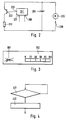
- Fig. 2 shows an embodiment for the implementation of the invention Procedure required components.
- a microprocessor has two inputs 207 and 208 assigned.
- a signal is fed to the microprocessor via input 208 if a Start of operations, i.e. the device is switched on.
- a signal is sent to the microprocessor via input 207 as to whether the device is on the network is connected or not.
- the predetermined maximum value of the counter reading and 1 is an output signal in the microprocessor generated, which is output via the output 206.
- a controllable switch 202 which can be a transistor, is driven.
- this controllable switch can be a resistor 203 to the terminals of a Accumulator 204 are closed and this accumulator discharged.
- a motor 205 is also attached to this accumulator is connected to the via a switch 209 to be operated by the user Accumulator can be connected.
- Fig. 3 shows the representation of a display in which the user the beginning of a Can recognize discharge and charge cycle of the battery.
- display parts are driven, which in the state of charge of the battery Show percent. So that the user during the discharge and charge cycle through the changing percentage of the charge capacity of the battery is not irritating (the user sees that the device is switched off and still registers one Display of the change in the state of charge of the battery) is replaced by another Icon 301 indicates to the user that such a discharge and charge cycle has begun.
- This symbol is, according to the illustration in FIG. 3, logically so chosen so that the user is simultaneously shown that he is in this state if possible should not pull the plug.
- step 501 the time window that starts in step 102 is reset has been. According to step 502, it is then checked whether since the last The required minimum interruption time has passed. This is done by checking whether a started time block has expired is or whether the currently determined usage action within the time block took place. This block of time is expediently dimensioned so that the The magnitude of this time block corresponds to the duration of the discharge and charge cycle.
- step 502 It was determined in step 502 that the required minimum interruption time had expired, i.e. that the time block had expired, there is a reset in step 503 with subsequent restart of the Time block.
- step 504 a first counter is incremented that the Usage acts in one block counts. I.e. the acts of use, between who must have had the required minimum interruption time, so this block and i.e. this set of uses in the number of counted uses.
- the number of in this block summarized acts of use can be of the order of approx. 10 lie.
- step 505 it is then checked whether this first counter is his has reached the predetermined maximum value. According to the above, it will checks whether this first counter has reached the value 10. If this is the case, a second counter incremented.
- step 506 This counter counts the blocks of usage acts, that have been successfully completed, i.e. the blocks, in each case between the individual usage actions the minimum interruption time has been reached.
- step 506 counter 1 is reset in step 507, i.e. of the first Counter that counts the individual usage actions in a block.
- step 508 a time block flag is then set to the value 0. With this time block flag indicates that a block of time was successfully completed, in which between the required actions in a block Minimum break time was given.
- step 505 it was determined that the Counter 1 has not yet reached its maximum value, a transition takes place immediately to step 106 according to method 1. This also includes step 508 Transition to step 106 of FIG. 1.
- step 502 it was determined that the block of time had not expired since the last use, takes place in step 509 a reset of the counter 1. That is. all acts of use previously in this block have been counted, are discarded by this detected fault. The detected malfunction is that between two acts of use not the required minimum interruption time was given. This then takes place in step 510 a reset and a subsequent restart of the time block.
- Step 106 checks the counter 2 for its maximum value. Since this counter 2 Blocks of usage actions counts can be given according to the given number of Usage acts in the blocks the maximum value of counter 2 in the Range from 15 to 20. Accordingly, a reset takes place in step 111 this counter 2.
- step 107 it can additionally be checked in step 107 whether that Time block flag has the value 0. This is only the case if the last block of individual uses have been successfully counted. I.e. that in the the necessary time between the individual uses Minimum interruption time has been reached.
Landscapes
- Engineering & Computer Science (AREA)
- Power Engineering (AREA)
- Manufacturing & Machinery (AREA)
- Chemical & Material Sciences (AREA)
- Chemical Kinetics & Catalysis (AREA)
- Electrochemistry (AREA)
- General Chemical & Material Sciences (AREA)
- Charge And Discharge Circuits For Batteries Or The Like (AREA)
- Secondary Cells (AREA)
- Crystals, And After-Treatments Of Crystals (AREA)
Description
- Fig. 1
- ein Ablaufdiagramm des Verfahrens,
- Fig. 2
- eine Darstellung der für die Durchführung des erfindungsgemäßen Verfahrens benötigten Bauteile,
- Fig. 3
- ein Display, in dem dem Benutzer der Beginn eines Entlade- und Ladezyklus des Akkumulators angezeigt wird,
- Fig. 4
- ein Blockschaltbild des Verfahrensablaufes, wenn der Akku während des Betriebs entladen wird und
- Fig. 5
- eine Variation eines Teiles des Ablaufdiagrammes.
Claims (12)
- Verfahren zur Pflege eines Akkus eines Geräts, bei dem in bestimmten Abständen der Akku einem Entlade- und Ladezyklus unterworfen wird, durch den dieser zumindest nahezu vollständig entladen wird, bei dem die Benutzungen des Geräts gezählt werden (105, 501 bis 511), und bei Erreichen einer vorgegebenen Anzahl von Benutzungen (106) ein Zyklus gestartet wird, sofern das Gerät ans Netz angeschlossen ist (107), in dem der Akku zunächst über einen Verbraucher vollständig entladen (108, 110) und anschließend wieder geladen wird (112, 113) und bei dem nach diesem Entlade-/Ladezyklus erneut die Benutzungen des Geräts gezählt werden (105).
- Verfahren nach Anspruch 1, dadurch gekennzeichnet, daß beim Einschalten des Gerätes nur dann eine erneute Benutzung gezählt wird, wenn seit der letzten Benutzung eine bestimmte Zeit vergangen ist (102, 103).
- Verfahren nach Anspruch 1 oder 2, dadurch gekennzeichnet, daß das Entladen des Akkus abgebrochen wird, wenn während des Entladens der Netzanschluß des Gerätes unterbrochen und/oder das Gerät eingeschaltet wird (109).
- Verfahren nach einem der Ansprüche 1 bis 3, dadurch gekennzeichnet, daß der Entlade-/Ladezyklus erst nach Verstreichen einer bestimmten Zeitdauer nach einer beendeten Benutzung des Gerätes gestartet wird (107).
- Verfahren nach einem der Ansprüche 1 bis 4, dadurch gekennzeichnet, daß die Benutzungen des Gerätes bis zum Einsetzen eines Entlade-/Ladezyklus erneut gezählt werden, wenn der Akku während des Betriebs des Gerätes entladen wird (401, 402).
- Verfahren nach Anspruch 1, dadurch gekennzeichnet, daß dem Benutzer die Durchführung des Entlade-/Ladezyklus auf dem Display angezeigt wird (301, 302).
- Verfahren nach Anspruch 6, dadurch gekennzeichnet, daß dem Benutzer ein Symbol angezeigt wird, daß der Netzstecker nicht gezogen werden darf (301).
- Verfahren nach einem der Ansprüche 1 bis 7, dadurch gekennzeichnet, daß nur Benutzungen gezählt werden, bei denen seit der vorhergehenden Benutzung eine Mindestunterbrechungszeit gegeben ist.
- Verfahren nach Anspruch 8, dadurch gekennzeichnet, daß mehrere Benutzungen nur dann gezählt werden, wenn bei jeder dieser Benutzungen seit der vorhergehenden Benutzung die Mindestunterbrechungszeit gegeben war.
- Verfahren nach Anspruch 9, dadurch gekennzeichnet, daß der Entlade-/Ladezyklus erst dann durchgeführt wird, wenn bei mehreren vorausgehenden Benutzungen seit der jeweils vorhergehenden Benutzung die Mindestunterbrechungszeit gegeben war.
- Vorrichtung zum Entladen und Laden eines Akkus eines Geräts gemäß dem Verfahren nach einem der vorhergehenden Ansprüche, dadurch gekennzeichnet, daß einem Mikroprozessor (201) ein Signal (207) zuführbar ist, das anzeigt, ob das Gerät ans Netz angeschlossen ist, daß der Mikroprozessor einen Zähler für die Benutzungen des Gerätes aufweist, daß in dem Mikroprozessor ein Vergleich stattfinden kann, ob der Zählerstand einen vorgegebenen Maximalwert überschreitet, daß von dem Mikroprozessor über einen Ausgang (206) ein steuerbarer Schalter (202), insbesondere ein Transistor, ansteuerbar ist, und daß über diesen steuerbaren Schalter (202) ein Verbraucher (203) mit den Klemmen des Akkus (204) verbindbar ist.
- Vorrichtung nach Anspruch 11, dadurch gekennzeichnet, daß das Gerät ein Haarschneidapparat, insbesondere ein Rasierer oder Bartschneider ist.
Applications Claiming Priority (3)
| Application Number | Priority Date | Filing Date | Title |
|---|---|---|---|
| DE4409736A DE4409736A1 (de) | 1994-03-22 | 1994-03-22 | Verfahren und Vorrichtung zur Pflege von in einem Gerät fest eingebauten Akkus |
| DE4409736 | 1994-03-22 | ||
| PCT/EP1995/000674 WO1995026066A1 (de) | 1994-03-22 | 1995-02-24 | Verfahren und vorrichtung zur pflege von in einem gerät fest eingebauten akkus |
Publications (2)
| Publication Number | Publication Date |
|---|---|
| EP0752168A1 EP0752168A1 (de) | 1997-01-08 |
| EP0752168B1 true EP0752168B1 (de) | 1999-09-08 |
Family
ID=6513439
Family Applications (1)
| Application Number | Title | Priority Date | Filing Date |
|---|---|---|---|
| EP95911263A Expired - Lifetime EP0752168B1 (de) | 1994-03-22 | 1995-02-24 | Verfahren und vorrichtung zur pflege eines akkus eines geräts |
Country Status (6)
| Country | Link |
|---|---|
| US (1) | US5793188A (de) |
| EP (1) | EP0752168B1 (de) |
| JP (1) | JPH09510600A (de) |
| AT (1) | ATE184432T1 (de) |
| DE (2) | DE4409736A1 (de) |
| WO (1) | WO1995026066A1 (de) |
Families Citing this family (16)
| Publication number | Priority date | Publication date | Assignee | Title |
|---|---|---|---|---|
| DE19612089A1 (de) * | 1996-03-27 | 1997-10-02 | Braun Ag | Elektrischer Rasierapparat oder damit zusammenwirkendes Gerät und Anordnung zur Auswertung von Informationen |
| US6025695A (en) * | 1997-07-09 | 2000-02-15 | Friel; Daniel D. | Battery operating system |
| US5965997A (en) * | 1997-08-20 | 1999-10-12 | Benchmarq Microelectronics | Battery monitoring circuit with storage of charge and discharge accumulation values accessible therefrom |
| TW363771U (en) * | 1998-04-01 | 1999-07-01 | Asustek Comp Inc | Portable calibration structure for computer battery capacity |
| DE19921677A1 (de) | 1999-05-18 | 2000-11-23 | Braun Gmbh | Zusatzgerät für ein Elektrokleingerät und Verfahren zur Erkennung einer elektrischen und/oder magnetischen Verbindung zwischen den Geräten |
| US6700352B1 (en) | 1999-11-11 | 2004-03-02 | Radiant Power Corp. | Dual capacitor/battery charger |
| EP1160953B1 (de) * | 2000-05-29 | 2009-12-02 | Panasonic Corporation | Batterieladeverfahren |
| FR2811486B1 (fr) * | 2000-07-06 | 2002-10-11 | Renault | Procede de gestion d'une batterie d'accumulateurs |
| WO2003034568A1 (en) * | 2000-11-10 | 2003-04-24 | Radiant Power Corporation | Dual capacitor/battery charger |
| EP1335475A1 (de) * | 2002-02-08 | 2003-08-13 | Trilectron Industries, Inc. | Dual Kondensator/Batterie Lader |
| DE10223557A1 (de) | 2002-05-28 | 2003-12-18 | Braun Gmbh | Verfahren zur Pflege einer wiederaufladbaren Batterie |
| US7135839B2 (en) * | 2002-12-05 | 2006-11-14 | Matsushita Electric Industrial Co., Ltd. | Battery pack and method of charging and discharging the same |
| US7622895B1 (en) | 2006-03-23 | 2009-11-24 | Griffin Technology, Inc. | Power level display calibration device |
| JP2009124795A (ja) * | 2007-11-12 | 2009-06-04 | Sony Corp | 充電方法および装置 |
| JP5647957B2 (ja) * | 2010-09-10 | 2015-01-07 | 富士フイルム株式会社 | 超音波診断装置 |
| US9660467B2 (en) * | 2015-04-09 | 2017-05-23 | TwinTech Industry, Inc. | Portable powerbank with integrated promotional-video capabilities and methods of use |
Family Cites Families (12)
| Publication number | Priority date | Publication date | Assignee | Title |
|---|---|---|---|---|
| DE3205390A1 (de) * | 1981-02-17 | 1982-11-18 | Utah Research & Development Co., 84104 Salt Lake City, Utah | Programmierbare vorrichtung zur wartung von batterien |
| US4455523A (en) * | 1982-06-07 | 1984-06-19 | Norand Corporation | Portable battery powered system |
| US4885523A (en) * | 1988-03-15 | 1989-12-05 | Norand Corporation | Battery conditioning system having communication with battery parameter memory means in conjunction with battery conditioning |
| DE3340882C1 (de) * | 1983-11-11 | 1985-06-27 | Messerschmitt-Bölkow-Blohm GmbH, 8012 Ottobrunn | Vorrichtung zur Temperaturkontrolle und zur Rekonditionierung von Batterien aus elektro-chemischen Einzelzellen |
| GB2175759B (en) * | 1985-06-01 | 1989-07-12 | Britonics Limited | Improvements in or relating to rechargeable battery systems |
| US4703247A (en) * | 1985-07-19 | 1987-10-27 | Sanyo Electric Co., Ltd. | Battery apparatus for an electric shaver |
| NL8601243A (nl) * | 1986-05-15 | 1987-12-01 | Philips Nv | Inrichting voor het weergeven van de ladingstoestand van een batterij. |
| US4849681A (en) * | 1987-07-07 | 1989-07-18 | U.S. Philips Corporation | Battery-powered device |
| US4835453A (en) * | 1987-07-07 | 1989-05-30 | U.S. Philips Corp. | Battery-powered device |
| JPH01313783A (ja) * | 1988-06-14 | 1989-12-19 | Philips Kk | 電池の容量計測回路 |
| US5445894A (en) * | 1991-04-22 | 1995-08-29 | Dow Corning Corporation | Ceramic coatings |
| DE4219999A1 (de) * | 1992-06-19 | 1993-12-23 | Bosch Gmbh Robert | Ladeeinrichtung |
-
1994
- 1994-03-22 DE DE4409736A patent/DE4409736A1/de not_active Withdrawn
-
1995
- 1995-02-24 WO PCT/EP1995/000674 patent/WO1995026066A1/de not_active Ceased
- 1995-02-24 JP JP7524325A patent/JPH09510600A/ja active Pending
- 1995-02-24 EP EP95911263A patent/EP0752168B1/de not_active Expired - Lifetime
- 1995-02-24 DE DE59506798T patent/DE59506798D1/de not_active Expired - Lifetime
- 1995-02-24 AT AT95911263T patent/ATE184432T1/de not_active IP Right Cessation
- 1995-02-24 US US08/704,578 patent/US5793188A/en not_active Expired - Lifetime
Also Published As
| Publication number | Publication date |
|---|---|
| DE4409736A1 (de) | 1995-09-28 |
| ATE184432T1 (de) | 1999-09-15 |
| US5793188A (en) | 1998-08-11 |
| EP0752168A1 (de) | 1997-01-08 |
| DE59506798D1 (de) | 1999-10-14 |
| JPH09510600A (ja) | 1997-10-21 |
| WO1995026066A1 (de) | 1995-09-28 |
Similar Documents
| Publication | Publication Date | Title |
|---|---|---|
| EP0752168B1 (de) | Verfahren und vorrichtung zur pflege eines akkus eines geräts | |
| EP0787306B1 (de) | Verfahren zur bestimmung des ladezustandes eines akkumulators | |
| DE4225088C2 (de) | Batterieentladevorrichtung | |
| DE69409863T2 (de) | Batterieladegerät | |
| DE69532539T2 (de) | Parametermessverfahren,Verfahren und Vorrichtung zur Steuerung des Ladens und Entladens und Verfahren zur Bestimmung des Lebensendes für Sekundärbatterien und damit ausgerüstetes Energiespeichergerät | |
| EP0680613B1 (de) | Verfahren zur ermittlung des ladezustandes einer batterie, insbesondere einer fahrzeug-starterbatterie | |
| EP1405384B1 (de) | Vorrichtungen und/oder verfahren zur bestimmung der verfügbarkeit von elektrischer energie insbesondere in bordnetzen mit mehreren energiespeichern | |
| EP0500520B1 (de) | Verfahren zum betrieb einer von mindestens einem wiederaufladbaren akkumulator gespeisten aufzeichnungseinrichtung | |
| DE102021206199A1 (de) | Batteriesteuereinheit und Batteriesystem | |
| DE10362316B4 (de) | System für das Laden einer Batterie | |
| DE102018127502B4 (de) | Wiederanlaufschutzvorrichtung | |
| DE102011089962A1 (de) | Verfahren zur Temperaturregelung von mindestens einem Batterieelement, Batterie sowie Kraftfahrzeug mit einer solchen Batterie | |
| DE1638085B2 (de) | Verfahren und Schaltungsanordnung zum Schnelladen einer elektrischen Batterie | |
| DE2753514A1 (de) | Batterieladegeraet-steuerschaltung | |
| DE2400090B2 (de) | Verfahren und Schaltungsanordnung zum Laden von Akkumulatoren | |
| EP0114871B1 (de) | Verfahren und vorrichtung zum überwachen der jeweils eingeladenen kapazität von akkumulatoren | |
| CH701697A1 (de) | Unterbrechungsfreie Stromversorgung für ein medizinisches Verabreichungsgerät. | |
| EP3720733B1 (de) | Verfahren zum steuern einer elektrischen anlage eines elektrisch antreibbaren kraftfahrzeugs mit mehreren batterien sowie elektrische anlage eines elektrisch antreibbaren kraftfahrzeugs | |
| DE102020209397A1 (de) | Verfahren zur Erfassung von elektrischen Fehlerzuständen eines Wechselakkupacks sowie System zur Durchführung des Verfahrens | |
| DE102020209396A1 (de) | Verfahren zur Erfassung von elektrischen Fehlerzuständen in einem Wechselakkupack und System zur Durchführung des Verfahrens | |
| EP0068523A1 (de) | Schaltungsanordnung zum Laden einer Akkumulatorbatterie mit pulsierendem Gleichstrom | |
| DE2631974C2 (de) | Verfahren zur Beendigung des Ladevorganges einer Akkumulatorenbatterie | |
| WO2021121834A1 (de) | Verfahren zum betrieb einer batterie | |
| EP0893870A2 (de) | Netzspannungsversorgungseinrichtung | |
| DE102017202650A1 (de) | Energiespeichersystem für ein Kraftfahrzeug sowie Betriebsverfahren |
Legal Events
| Date | Code | Title | Description |
|---|---|---|---|
| PUAI | Public reference made under article 153(3) epc to a published international application that has entered the european phase |
Free format text: ORIGINAL CODE: 0009012 |
|
| 17P | Request for examination filed |
Effective date: 19961001 |
|
| AK | Designated contracting states |
Kind code of ref document: A1 Designated state(s): AT CH DE FR GB LI NL |
|
| 17Q | First examination report despatched |
Effective date: 19971105 |
|
| GRAG | Despatch of communication of intention to grant |
Free format text: ORIGINAL CODE: EPIDOS AGRA |
|
| GRAG | Despatch of communication of intention to grant |
Free format text: ORIGINAL CODE: EPIDOS AGRA |
|
| GRAH | Despatch of communication of intention to grant a patent |
Free format text: ORIGINAL CODE: EPIDOS IGRA |
|
| GRAH | Despatch of communication of intention to grant a patent |
Free format text: ORIGINAL CODE: EPIDOS IGRA |
|
| GRAA | (expected) grant |
Free format text: ORIGINAL CODE: 0009210 |
|
| AK | Designated contracting states |
Kind code of ref document: B1 Designated state(s): AT CH DE FR GB LI NL |
|
| REF | Corresponds to: |
Ref document number: 184432 Country of ref document: AT Date of ref document: 19990915 Kind code of ref document: T |
|
| REG | Reference to a national code |
Ref country code: CH Ref legal event code: NV Representative=s name: LUCHS & PARTNER PATENTANWAELTE Ref country code: CH Ref legal event code: EP |
|
| GBT | Gb: translation of ep patent filed (gb section 77(6)(a)/1977) |
Effective date: 19990910 |
|
| REF | Corresponds to: |
Ref document number: 59506798 Country of ref document: DE Date of ref document: 19991014 |
|
| RAP2 | Party data changed (patent owner data changed or rights of a patent transferred) |
Owner name: BRAUN GMBH |
|
| ET | Fr: translation filed | ||
| NLT2 | Nl: modifications (of names), taken from the european patent patent bulletin |
Owner name: BRAUN GMBH |
|
| REG | Reference to a national code |
Ref country code: FR Ref legal event code: CD Ref country code: FR Ref legal event code: CA |
|
| PLBE | No opposition filed within time limit |
Free format text: ORIGINAL CODE: 0009261 |
|
| STAA | Information on the status of an ep patent application or granted ep patent |
Free format text: STATUS: NO OPPOSITION FILED WITHIN TIME LIMIT |
|
| REG | Reference to a national code |
Ref country code: CH Ref legal event code: PFA Free format text: BRAUN AKTIENGESELLSCHAFT TRANSFER- BRAUN AKTIENGESELLSCHAFT;BRAUN GMBH |
|
| 26N | No opposition filed | ||
| REG | Reference to a national code |
Ref country code: GB Ref legal event code: IF02 |
|
| PGFP | Annual fee paid to national office [announced via postgrant information from national office to epo] |
Ref country code: FR Payment date: 20060217 Year of fee payment: 12 |
|
| PGFP | Annual fee paid to national office [announced via postgrant information from national office to epo] |
Ref country code: CH Payment date: 20060220 Year of fee payment: 12 |
|
| PG25 | Lapsed in a contracting state [announced via postgrant information from national office to epo] |
Ref country code: LI Free format text: LAPSE BECAUSE OF NON-PAYMENT OF DUE FEES Effective date: 20070228 Ref country code: CH Free format text: LAPSE BECAUSE OF NON-PAYMENT OF DUE FEES Effective date: 20070228 |
|
| REG | Reference to a national code |
Ref country code: CH Ref legal event code: PL |
|
| REG | Reference to a national code |
Ref country code: FR Ref legal event code: ST Effective date: 20071030 |
|
| PG25 | Lapsed in a contracting state [announced via postgrant information from national office to epo] |
Ref country code: FR Free format text: LAPSE BECAUSE OF NON-PAYMENT OF DUE FEES Effective date: 20070228 |
|
| PGFP | Annual fee paid to national office [announced via postgrant information from national office to epo] |
Ref country code: NL Payment date: 20080226 Year of fee payment: 14 Ref country code: GB Payment date: 20080219 Year of fee payment: 14 |
|
| PGFP | Annual fee paid to national office [announced via postgrant information from national office to epo] |
Ref country code: AT Payment date: 20080226 Year of fee payment: 14 |
|
| GBPC | Gb: european patent ceased through non-payment of renewal fee |
Effective date: 20090224 |
|
| PG25 | Lapsed in a contracting state [announced via postgrant information from national office to epo] |
Ref country code: AT Free format text: LAPSE BECAUSE OF NON-PAYMENT OF DUE FEES Effective date: 20090224 |
|
| NLV4 | Nl: lapsed or anulled due to non-payment of the annual fee |
Effective date: 20090901 |
|
| PG25 | Lapsed in a contracting state [announced via postgrant information from national office to epo] |
Ref country code: NL Free format text: LAPSE BECAUSE OF NON-PAYMENT OF DUE FEES Effective date: 20090901 |
|
| PG25 | Lapsed in a contracting state [announced via postgrant information from national office to epo] |
Ref country code: GB Free format text: LAPSE BECAUSE OF NON-PAYMENT OF DUE FEES Effective date: 20090224 |
|
| PGFP | Annual fee paid to national office [announced via postgrant information from national office to epo] |
Ref country code: DE Payment date: 20100226 Year of fee payment: 16 |
|
| REG | Reference to a national code |
Ref country code: DE Ref legal event code: R119 Ref document number: 59506798 Country of ref document: DE Effective date: 20110901 |
|
| PG25 | Lapsed in a contracting state [announced via postgrant information from national office to epo] |
Ref country code: DE Free format text: LAPSE BECAUSE OF NON-PAYMENT OF DUE FEES Effective date: 20110901 |