EP0752168B1 - Process and arrangement for the maintenance of a battery in a device - Google Patents
Process and arrangement for the maintenance of a battery in a device Download PDFInfo
- Publication number
- EP0752168B1 EP0752168B1 EP95911263A EP95911263A EP0752168B1 EP 0752168 B1 EP0752168 B1 EP 0752168B1 EP 95911263 A EP95911263 A EP 95911263A EP 95911263 A EP95911263 A EP 95911263A EP 0752168 B1 EP0752168 B1 EP 0752168B1
- Authority
- EP
- European Patent Office
- Prior art keywords
- discharge
- accumulator
- battery
- charge cycle
- cycle
- Prior art date
- Legal status (The legal status is an assumption and is not a legal conclusion. Google has not performed a legal analysis and makes no representation as to the accuracy of the status listed.)
- Expired - Lifetime
Links
Images


Classifications
-
- H—ELECTRICITY
- H01—ELECTRIC ELEMENTS
- H01M—PROCESSES OR MEANS, e.g. BATTERIES, FOR THE DIRECT CONVERSION OF CHEMICAL ENERGY INTO ELECTRICAL ENERGY
- H01M10/00—Secondary cells; Manufacture thereof
- H01M10/42—Methods or arrangements for servicing or maintenance of secondary cells or secondary half-cells
- H01M10/44—Methods for charging or discharging
-
- H—ELECTRICITY
- H02—GENERATION; CONVERSION OR DISTRIBUTION OF ELECTRIC POWER
- H02J—CIRCUIT ARRANGEMENTS OR SYSTEMS FOR SUPPLYING OR DISTRIBUTING ELECTRIC POWER; SYSTEMS FOR STORING ELECTRIC ENERGY
- H02J7/00—Circuit arrangements for charging or depolarising batteries or for supplying loads from batteries
- H02J7/0069—Charging or discharging for charge maintenance, battery initiation or rejuvenation
-
- Y—GENERAL TAGGING OF NEW TECHNOLOGICAL DEVELOPMENTS; GENERAL TAGGING OF CROSS-SECTIONAL TECHNOLOGIES SPANNING OVER SEVERAL SECTIONS OF THE IPC; TECHNICAL SUBJECTS COVERED BY FORMER USPC CROSS-REFERENCE ART COLLECTIONS [XRACs] AND DIGESTS
- Y02—TECHNOLOGIES OR APPLICATIONS FOR MITIGATION OR ADAPTATION AGAINST CLIMATE CHANGE
- Y02E—REDUCTION OF GREENHOUSE GAS [GHG] EMISSIONS, RELATED TO ENERGY GENERATION, TRANSMISSION OR DISTRIBUTION
- Y02E60/00—Enabling technologies; Technologies with a potential or indirect contribution to GHG emissions mitigation
- Y02E60/10—Energy storage using batteries
-
- Y—GENERAL TAGGING OF NEW TECHNOLOGICAL DEVELOPMENTS; GENERAL TAGGING OF CROSS-SECTIONAL TECHNOLOGIES SPANNING OVER SEVERAL SECTIONS OF THE IPC; TECHNICAL SUBJECTS COVERED BY FORMER USPC CROSS-REFERENCE ART COLLECTIONS [XRACs] AND DIGESTS
- Y10—TECHNICAL SUBJECTS COVERED BY FORMER USPC
- Y10S—TECHNICAL SUBJECTS COVERED BY FORMER USPC CROSS-REFERENCE ART COLLECTIONS [XRACs] AND DIGESTS
- Y10S320/00—Electricity: battery or capacitor charging or discharging
- Y10S320/18—Indicator or display
- Y10S320/21—State of charge of battery
Definitions
- the invention relates to a method for maintaining a battery of a device Claim 1 and a device for performing the The method of claim 11.
- the object of the present invention is to provide the user of a device with optional Mains / battery operation to facilitate the use of such a device as much as possible and to achieve the longest possible battery life even if the device is frequently operated on the mains.
- the battery is advantageously discharged and charged only when the device is connected to the network so that the device is not discharged when a subsequent loading is not possible. This means that the device over the Mains plug must be connected to the mains or that the device holder must be connected to the mains connected and the device must be in the device holder.
- the measures according to claim 2 advantageously prevent a accidentally switching off and then on again during use as separate uses is counted.
- the configuration according to claim 3 can be prevented that the battery is fully discharged if one does not discharge while the battery is being discharged intended operating condition occurs.
- the measure according to claim 4 prevents the battery from being discharged, if the device is disconnected from the mains after use, so that a charge after the discharge would not be possible.
- the battery is empty can be achieved during normal operation in this procedure to maintain the Batteries included. That is, the unloading and loading process according to the invention is not is done unnecessarily often.
- the user of the device this discharging and charging process of the battery is shown on the display. This is particularly advantageous in devices in which the current display is used The charge status of the battery is displayed. This display will then appear during the Unloading and subsequent charging is controlled normally, so that the user due to the changing display of the display the discharge and charge process as can recognize such.
- Step 101 checks whether the device has started to operate, i.e. whether the device is switched on.
- the device is a razor.
- step 102 in which a time window is started.
- step 103 it is checked whether an on during this time window operation has started again. If, before this time window expires, a new one Start of operation, it can be assumed that it is, for example accidental on / off switching during a shave, so this is not considered separate shaves are counted. Thus, according to step 103 before the expiry of the If a new start of operation is registered in the time window, a reset takes place in step 104 of the time window, i.e. the length of time from which it is concluded that it is a shaving again begins to count again. It then takes place Transition to step 102.
- This time window can be of the order of magnitude about 10 minutes.
- step 105 a counter is incremented that the individual shaving processes, i.e. the uses of the razor counts.
- Step 106 checks whether whether the counter reading is greater than or equal to a predetermined maximum value, i.e. if the number of uses has reached a predetermined frequency. This maximum value is chosen so that unloading and the battery is then charged. If one assumes that the user of a Shavers shave once a day and load or unload approximately every 6 This maximum of the meter reading can take place in the months, for example Order of magnitude of 180. So if this meter reading is less than its maximum, there is again a transition to step 101. This has to be the counter reading A maximum is reached, a transition is made to step 107.
- step 107 a check is made in step 107 as to whether that Device is still connected to the mains. It can also be advantageous additionally check whether the mains voltage is above a threshold of for example, 100 V. This then makes the discharge / charge cycle advantageous avoided if the device is connected to a 12 V DC voltage source Cars, boats or campers are connected and therefore the charging process would take a comparatively long time.
- Step 107 also checks whether the device is not in operation. Furthermore can be checked in step 107 whether the battery is fully charged. This can for example, by moving from the "load” state to the state "Trickle charge” is recognized. This last test step is especially then useful if the check in step 110 - as explained below - on it is based on checking whether the predetermined period of time has expired. If the battery then only "fully” discharged from the charge state, it is ensured that when exiting a defined discharge state has been reached.
- step 107 If one of the checks in step 107 yields a negative result, an is carried out Transition to step 101.
- step 108 If the device is connected to the mains, the battery in step 108 unload. This happens by connecting a resistor to the battery, so that this resistor discharges the battery. During this step 108 is always at the same time checked in step 109 whether the network connection is interrupted. In this case, the discharge and charge cycle is interrupted and a transition to step 112 and as soon as the device is connected to the mains again charging the battery. The same termination of the charging and discharging cycle takes place according to the Check in step 109 if the device is discharged during the period of the user is switched on. At the same time, step 110 checks whether the Battery is discharged. This can be done, for example, by setting the resistance for one predetermined time is connected to the battery.
- the discharge status of the battery is recognized when the specified time has expired. For example a time to discharge the battery of a shaver on the order of 6 hours lie. It is also conceivable, however, during the unloading process Observe the state of charge of the battery and according to the then specified Conditions, for example by measuring the terminal voltage of the battery determine the corresponding charge or discharge status of the battery.
- Step 113 checks whether the battery is full again. This is not the case, rapid charging continues according to step 112.
- step 101 the time window is set to zero and the counter is set to zero, i.e. with a
- the method starts again from step 101.
- Razors have a fast charging time of the order of 1 Hour. If one sets for the length of time that elapses before checking in step 107, whether the device is still connected to the network, a time period of the order of magnitude from 1/2 to 1 hour, there is a total waiting time plus unloading time plus charging time of the order of 7 to 8 hours.
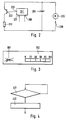
- Fig. 2 shows an embodiment for the implementation of the invention Procedure required components.
- a microprocessor has two inputs 207 and 208 assigned.
- a signal is fed to the microprocessor via input 208 if a Start of operations, i.e. the device is switched on.
- a signal is sent to the microprocessor via input 207 as to whether the device is on the network is connected or not.
- the predetermined maximum value of the counter reading and 1 is an output signal in the microprocessor generated, which is output via the output 206.
- a controllable switch 202 which can be a transistor, is driven.
- this controllable switch can be a resistor 203 to the terminals of a Accumulator 204 are closed and this accumulator discharged.
- a motor 205 is also attached to this accumulator is connected to the via a switch 209 to be operated by the user Accumulator can be connected.
- Fig. 3 shows the representation of a display in which the user the beginning of a Can recognize discharge and charge cycle of the battery.
- display parts are driven, which in the state of charge of the battery Show percent. So that the user during the discharge and charge cycle through the changing percentage of the charge capacity of the battery is not irritating (the user sees that the device is switched off and still registers one Display of the change in the state of charge of the battery) is replaced by another Icon 301 indicates to the user that such a discharge and charge cycle has begun.
- This symbol is, according to the illustration in FIG. 3, logically so chosen so that the user is simultaneously shown that he is in this state if possible should not pull the plug.
- step 501 the time window that starts in step 102 is reset has been. According to step 502, it is then checked whether since the last The required minimum interruption time has passed. This is done by checking whether a started time block has expired is or whether the currently determined usage action within the time block took place. This block of time is expediently dimensioned so that the The magnitude of this time block corresponds to the duration of the discharge and charge cycle.
- step 502 It was determined in step 502 that the required minimum interruption time had expired, i.e. that the time block had expired, there is a reset in step 503 with subsequent restart of the Time block.
- step 504 a first counter is incremented that the Usage acts in one block counts. I.e. the acts of use, between who must have had the required minimum interruption time, so this block and i.e. this set of uses in the number of counted uses.
- the number of in this block summarized acts of use can be of the order of approx. 10 lie.
- step 505 it is then checked whether this first counter is his has reached the predetermined maximum value. According to the above, it will checks whether this first counter has reached the value 10. If this is the case, a second counter incremented.
- step 506 This counter counts the blocks of usage acts, that have been successfully completed, i.e. the blocks, in each case between the individual usage actions the minimum interruption time has been reached.
- step 506 counter 1 is reset in step 507, i.e. of the first Counter that counts the individual usage actions in a block.
- step 508 a time block flag is then set to the value 0. With this time block flag indicates that a block of time was successfully completed, in which between the required actions in a block Minimum break time was given.
- step 505 it was determined that the Counter 1 has not yet reached its maximum value, a transition takes place immediately to step 106 according to method 1. This also includes step 508 Transition to step 106 of FIG. 1.
- step 502 it was determined that the block of time had not expired since the last use, takes place in step 509 a reset of the counter 1. That is. all acts of use previously in this block have been counted, are discarded by this detected fault. The detected malfunction is that between two acts of use not the required minimum interruption time was given. This then takes place in step 510 a reset and a subsequent restart of the time block.
- Step 106 checks the counter 2 for its maximum value. Since this counter 2 Blocks of usage actions counts can be given according to the given number of Usage acts in the blocks the maximum value of counter 2 in the Range from 15 to 20. Accordingly, a reset takes place in step 111 this counter 2.
- step 107 it can additionally be checked in step 107 whether that Time block flag has the value 0. This is only the case if the last block of individual uses have been successfully counted. I.e. that in the the necessary time between the individual uses Minimum interruption time has been reached.
Landscapes
- Engineering & Computer Science (AREA)
- Manufacturing & Machinery (AREA)
- Chemical & Material Sciences (AREA)
- Chemical Kinetics & Catalysis (AREA)
- Electrochemistry (AREA)
- General Chemical & Material Sciences (AREA)
- Power Engineering (AREA)
- Charge And Discharge Circuits For Batteries Or The Like (AREA)
- Crystals, And After-Treatments Of Crystals (AREA)
- Secondary Cells (AREA)
Abstract
Description
Die Erfindung betrifft ein Verfahren zur Pflege eines Akkus eines Geräts nach Patentanspruch 1 sowie eine Vorrichtung zur Durchführung des Verfahrens nach Anspruch 11.The invention relates to a method for maintaining a battery of a device Claim 1 and a device for performing the The method of claim 11.
Ein derartiges Verfahren ist bereits bekannt aus der Bedienungsanleitung zu dem Gerät "Braun Micron S", Druckdatum Oktober 1986. In dem Abschnitt unter der Überschrift "Akkupflege" ist dort beschrieben, daß die volle Ladekapazität des Akkus erhalten wird, wenn dieser zu Anfang, d.h. bei neuem Gerät, voll aufgeladen und durch Rasieren völlig entleert wird. Im Anschluß daran soll das Gerät wieder voll aufgeladen werden. Dieser Lade- und Entladevorgang soll dabei ca. zweimal im Jahr wiederholt werden. Dabei ist es notwendig, daß sich der Benutzer des Rasierers zumindest in etwa merkt, wann er zum letzten Mal diesen Entlade- und Ladezyklus des Akkus vorgenommen hat. Daraus muß der Benutzer dann wiederum selbsttätig den Zeitpunkt für den nächsten Entlade- und Ladezyklus bestimmen. Der Akku wird dabei über das Netz geladen, indem das Gerät mit einem Netzstecker an das Netz angeschlossen wird und die Netzspannung entsprechend gerichtet und gewandelt wird.Such a method is already known from the operating instructions for the device "Braun Micron S", printed in October 1986. In the section under the heading "Battery care" describes there that the full charge capacity of the battery is maintained, if at the beginning, i.e. with new device, fully charged and completely shaved is emptied. The device should then be fully charged again. This The charging and discharging process should be repeated approximately twice a year. It is it is necessary that the user of the razor at least approximately remembers when last performed this discharge and charge cycle of the battery. Out of it the user must then again automatically determine the time for the next one Determine the discharge and charge cycle. The battery is charged via the network by the device is connected to the mains with a mains plug and the mains voltage is directed and converted accordingly.
Weiterhin ist es aus dem Bereich elektrisch betriebener Zahnbürsten bekannt, eine Gerätehalterung der Zahnbürste mit einem Netzanschluß zu versehen. Der Akku der Zahnbürste wird dann induktiv geladen, wenn die Zahnbürste in die Gerätehalterung eingebracht wird.Furthermore, it is known from the field of electrically operated toothbrushes To provide the toothbrush holder with a mains connection. The battery of the Toothbrush is charged inductively when the toothbrush is in the device holder is introduced.
Aus der DE 33 40 882 C1 ist es bekannt, im Rahmen einer Akkupflege einen Akku über einen Widerstand mit einem positiven Temperaturkoeffizienten zu entladen. Durch diesen Widerstand soll bei der Entladung eine möglichst gleichmäßige Temperatur des Akkus erzielt werden, indem sich die Leistungsaufnahme des Widerstandes entsprechend der Temperatur anpaßt, wobei gleichzeitig der Widerstand und der Akkumulator derart miteinander vebunden sind, daß ein Wärmeaustausch stattfindet. Wenn der Akku entladen ist, soll er dann wieder aufgeladen werden.From DE 33 40 882 C1 it is known to use a battery as part of battery maintenance discharge a resistor with a positive temperature coefficient. By this resistance should be as uniform as possible when discharging Batteries can be achieved by changing the power consumption of the resistor adjusts according to the temperature, the resistance and the Accumulator are connected to each other in such a way that heat exchange takes place. If the battery is discharged, it should be recharged.
Weiterhin sind aus der DE 32 05 390 A1 und der DE 42 19 999 A1 Verfahren bekannt, bei denen unter Einsatz eines Mikroprozessors beim Laden eines Akkumulators zunächst eine Entladung vorgenommen wird.Methods are also known from DE 32 05 390 A1 and DE 42 19 999 A1, where using a microprocessor when charging a battery initially a discharge is carried out.
Aus der US-A-4,455,523 ist ein Batterie-Überwachungssystem bekannt, das eine genaue Anzeige des jeweiligen Ladezustands der wiederaufladbaren Batterie liefert, und dabei auch die Alterung der Batterie berücksichtigt. Dies erfolgt dadurch, daß erstens die Gesamtbetriebszeit der Batterie und die Anzahl der Entlade-/Ladezyklen gezählt werden und zweitens eine Messung der aktuellen Batteriekapazität durch Tiefentladung der Batterie erfolgt. Diese dient auch zur Konditionierung der Batterie. Zur Ermittlung des jeweiligen Ladezustands wird ferner der Batteriestrom während des Betriebs gemessen.From US-A-4,455,523 a battery monitoring system is known, the one provides accurate indication of the respective state of charge of the rechargeable battery, and the aging of the battery is also taken into account. This is because firstly the total operating time of the battery and the number of discharge / charge cycles counted secondly, a measurement of the current battery capacity through deep discharge the battery. This also serves to condition the battery. To determine the In addition, the battery current during operation is measured in the respective state of charge.
Aufgabe der vorliegenden Erfindung ist es, dem Benutzer eines Gerätes mit wahlweisem Netz-/Akkubetrieb die Benutzung des derartigen Gerätes weitestgehend zu erleichtern und dabei eine möglichst lange Lebensdauer des Akkus auch dann zu erreichen, wenn das Gerät häufig am Netz betrieben wird.The object of the present invention is to provide the user of a device with optional Mains / battery operation to facilitate the use of such a device as much as possible and to achieve the longest possible battery life even if the device is frequently operated on the mains.
Erfindungsgemäß wird diese Aufgabe durch die in den Ansprüchen 1 und 11 aufgeführten Merkmale gelöst. In vorteilhafter Weise erfolgt das Entladen und Laden des Akkus nur dann, wenn das Gerät mit dem Netz kontaktiert ist, so daß das Gerät nicht entladen wird, wenn ein anschließendes Laden nicht möglich ist. Dies bedeutet, daß das Gerät über den Netzstecker ans Netz angeschlossen sein muß oder daß die Gerätehalterung ans Netz angeschlossen sein und das Gerät sich in der Gerätehalterung befinden muß.According to the invention, this object is achieved by the features listed in claims 1 and 11. In The battery is advantageously discharged and charged only when the device is connected to the network so that the device is not discharged when a subsequent loading is not possible. This means that the device over the Mains plug must be connected to the mains or that the device holder must be connected to the mains connected and the device must be in the device holder.
Demgegenüber zeigt sich, daß bei dem genannten Stand der Technik keine Angaben gemacht sind, wie eine automatische Erkennung des Zeitpunktes erfolgen könnte, zu dem eine derartige Akkupflege stattfinden sollte.In contrast, it can be seen that no information is given in the prior art mentioned are made of how an automatic detection of the time could take place which such battery care should take place.
Durch die Maßnahmen nach Anspruch 2 wird vorteilhaft verhindert, daß ein versehentlichen Aus- und anschließendes Einschalten während einer Benutzung als separate Benutzungen gezählt wird.The measures according to claim 2 advantageously prevent a accidentally switching off and then on again during use as separate uses is counted.
Durch die Ausgestaltung nach Anspruch 3 kann verhindert werden, daß der Akku vollständig entladen wird, wenn während des Entladens des Akkus eine nicht vorgesehene Betriebsbedingung eintritt.The configuration according to claim 3 can be prevented that the battery is fully discharged if one does not discharge while the battery is being discharged intended operating condition occurs.
Durch die Maßnahme nach Anspruch 4 wird verhindert, daß der Akku entladen wird, wenn das Gerät nach der Benutzung vom Netz genommen wird, so daß ein Laden nach der Entladung nicht möglich wäre.The measure according to claim 4 prevents the battery from being discharged, if the device is disconnected from the mains after use, so that a charge after the discharge would not be possible.
In vorteilhafter Ausgestaltung nach Anspruch 5 werden Leerzustände des Akkus, die während des normalen Betriebes erreicht werden, in dieses Verfahren zur Pflege des Akkus einbezogen. D.h., daß der Entlade- und Ladevorgang nach der Erfindung nicht unnötig oft vorgenommen wird. In an advantageous embodiment according to claim 5, the battery is empty can be achieved during normal operation in this procedure to maintain the Batteries included. That is, the unloading and loading process according to the invention is not is done unnecessarily often.
In weiterer vorteilhafter Ausgestaltung nach Anspruch 6 wird dem Benutzer des Gerätes dieser Entlade- und Ladevorgang des Akkus über das Display angezeigt. Dies ist insbesondere in solchen Geräten vorteilhaft, in denen über ein Display der aktuelle Lade- zustand des Akkus angezeigt wird. Dieses Display wird dann während dem Entlade- und anschließenden Ladevorgangs normal angesteuert, so daß der Benutzer aufgrund der sich ändernden Anzeige des Display den Entlade- und Ladevorgang als solchen erkennen kann.In a further advantageous embodiment according to claim 6, the user of the device this discharging and charging process of the battery is shown on the display. This is This is particularly advantageous in devices in which the current display is used The charge status of the battery is displayed. This display will then appear during the Unloading and subsequent charging is controlled normally, so that the user due to the changing display of the display the discharge and charge process as can recognize such.
In einer besonders vorteilhaften Ausgestaltung nach Anspruch 7 kann dem Benutzer dann durch ein zusätzliches Symbol auf dem Display dieser Entlade- und Ladevorgang explizit angezeigt werden. Als Symbol bietet sich beispielsweise ein Netzstecker an, der durchkreuzt dargestellt ist. Dadurch wird dem Benutzer signalisiert, daß er während des Entlade- und anschließenden Ladevorganges den Netzstecker nicht ziehen darf, so daß ein Laden des Gerätes sicher möglich ist.In a particularly advantageous embodiment according to claim 7, the user then with an additional symbol on the display this unloading and charging process be displayed explicitly. A symbol, for example, is a power plug, the is shown crossed out. This signals to the user that he is during the Unloading and subsequent charging must not pull the mains plug, so that it is safe to charge the device.
Bei dem Gegenstand nach Anspruch 8 wird gewährleistet, daß der Entlade-/Ladezyklus nur dann vorgenommenwird, wenn der Zyklus zwischen zwei Benutzungen abgeschlossen werden kann.In the article according to claim 8 it is ensured that the discharge / charge cycle is only carried out if the cycle between two uses can be completed.
Gemäß Anspruch 9 wird gewährleistet, daß der Zyklus nur dann stattfindet, wenn die Zeiten zwischen den Benutzungen regelmäßig lang genug waren.According to claim 9 it is ensured that the cycle only takes place when the Times between uses were regularly long enough.
Gemäß Anspruch 10 wird gewährleistet, daß der Zyklus erst dann vorgenommen wird, wenn die Zeiten zwischen den Benutzungen in einem vergangenen Zeitraum regelmäßig lang genug waren.According to claim 10 it is ensured that the cycle is only carried out if the times between uses in a past period are regular were long enough.
Ein Ausführungsbeispiel der Erfindung ist in der Zeichnung dargestellt. Es zeigt:
- Fig. 1
- ein Ablaufdiagramm des Verfahrens,
- Fig. 2
- eine Darstellung der für die Durchführung des erfindungsgemäßen Verfahrens benötigten Bauteile,
- Fig. 3
- ein Display, in dem dem Benutzer der Beginn eines Entlade- und Ladezyklus des Akkumulators angezeigt wird,
- Fig. 4
- ein Blockschaltbild des Verfahrensablaufes, wenn der Akku während des Betriebs entladen wird und
- Fig. 5
- eine Variation eines Teiles des Ablaufdiagrammes.
- Fig. 1
- a flowchart of the method,
- Fig. 2
- a representation of the components required for carrying out the method according to the invention,
- Fig. 3
- a display in which the user is shown the start of a discharge and charge cycle of the battery,
- Fig. 4
- a block diagram of the procedure when the battery is discharged during operation and
- Fig. 5
- a variation of part of the flowchart.
Gemäß einer Ausgestaltung eines Ausführungsbeispiels nach Fig. 1 wird in einem
Schritt 101 geprüft, ob ein Betriebsbeginn des Gerätes vorliegt, d.h. ob das Gerät
eingeschaltet wird. Im vorliegenden Ausführungsbeispiel ist das Gerät ein Rasierapparat.According to an embodiment of an embodiment according to FIG. 1, in one
Ist dies der Fall, erfolgt ein Übergang zu dem Schritt 102, in dem ein Zeitfenster
gestartet wird. In dem Schritt 103 wird geprüft, ob während dieses Zeitfensters ein
erneuter Betriebsbeginn vorliegt. Wenn vor Ablauf dieses Zeitfensters ein erneuter
Betriebsbeginn vorliegt, ist davon auszugehen, daß es sich beispielsweise um ein
versehentliches Ein/Ausschalten während einer Rasur handelt, so daß dies nicht als
gesonderte Rasuren gezählt wird. Wird also gemäß dem Schritt 103 vor Ablauf des
Zeitfensters ein erneuter Betriebsbeginn registriert, erfolgt in dem Schritt 104 ein Reset
des Zeitfensters, d.h. die Zeitdauer, ab der geschlossen wird, daß es sich um einen
erneuten Rasiervorgang handelt, beginnt von neuem zu zählen. Es erfolgt dann ein
Übergang zu dem Schritt 102. Dieses Zeitfenster kann dabei in der Größenordnung von
ca. 10 Minuten liegen.If this is the case, there is a transition to
Wird während dieses Zeitfensters kein erneuter Betriebsbeginn registriert, erfolgt ein
Übergang zu dem Schritt 105. In dem Schritt 105 wird ein Zähler inkrementiert, der die
einzelnen Rasiervorgänge, d.h. die Benutzungen des Rasierers, zählt. Gleichzeitig erfolgt
in dem Schritt 105 ein Reset des Zeitfensters. In dem Schritt 106 wird dann überprüft,
ob der Zähler- stand größer oder gleich einem vorgegebenen Maximalwert ist, d.h. ob
die Zahl der Benutzungen eine vorgegebene Häufigkeit erreicht hat. Dieser Maximalwert
ist dabei so gewählt, daß in einem Zeitraum von einigen Monaten ein Entladen und
anschließendes Laden des Akkus erfolgt. Geht man davon aus, daß der Benutzer eines
Rasierapparates sich einmal am Tag rasiert und ein Laden bzw. Entladen ca. alle 6
Monate erfolgen soll, kann dieses Maximum des Zählerstandes beispielsweise in der
Größenordnung von 180 liegen. Ist dieser Zählerstand also kleiner als sein Maximum,
erfolgt ebenfalls wieder ein Übergang zu dem Schritt 101. Hat dieser Zählerstand sein
Maximum erreicht, erfolgt ein Übergang zu dem Schritt 107.If no new start of operation is registered during this time window, a will occur
Transition to step 105. In
Dort wird nach Ablauf einer bestimmten Zeitdauer geprüft, ob ein Entladen und anschließendes Laden des Akkus vorgenommen werden soll. Dieser Ablauf der bestimmten Zeitdauer dient dazu, zu verhindern, daß zwar unmittelbar nach der Rasur die Bedingungen für den Entlade- und Ladezyklus vorliegen, d.h., daß der Rasierapparat dann ans Netz angeschlossen ist, aber dann nach relativ kurzer Zeit vom Netz genommen wird, beispielsweise weil der Benutzer eine Reise antritt. Durch den Ablauf der bestimmten Zeitdauer, die in der Größenordnung einer halben bis einer Stunde liegen kann, wird in diesem Fall der Beginn eines Entlade-/Ladezyklus vermieden.After a certain period of time it is checked whether unloading and then the battery should be charged. This expiry of certain period of time is used to prevent that immediately after shaving the conditions for the discharge and charge cycle are met, i.e. the shaver then connected to the network, but then after a relatively short time from the network is taken, for example because the user is going on a trip. Through the process the specified length of time, which is of the order of half an hour to an hour the start of a discharge / charge cycle is avoided in this case.
Nach Ablauf dieser Zeitdauer erfolgt also in dem Schritt 107 eine Überprüfung, ob das
Gerät nach wie vor an das Netz angeschlossen ist. Dabei kann auch vorteilhaft
zusätzlich geprüft werden, ob die Netzspannung oberhalb eines Schwellwertes von
beispielsweise 100 V liegt. Dadurch wird der Entlade-/Ladezyklus vorteilhaft dann
vermieden, wenn das Gerät beispielsweise an eine 12 V-Gleichspannungsquelle eines
Autos, Bootes oder Campingmobiles angeschlossen ist und deswegen der Ladevorgang
vergleichsweise lange dauern würde.After this period of time has elapsed, a check is made in
In dem Schritt 107 wird außerdem geprüft, ob das Gerät nicht in Betrieb ist. Außerdem
kann in dem Schritt 107 geprüft werden, ob der Akku voll geladen ist. Dies kann
beispielsweise erfolgen, indem der Übergang vom Zustand "Laden" auf den Zustand
"Erhaltungsladung" erkannt wird. Dieser letzte Prüfschritt ist insbesondere dann
sinnvoll, wenn die Überprüfung in dem Schritt 110 - wie unten ausgeführt - darauf
beruht, zu prüfen, ob die fest vorgegebene Zeitdauer abgelaufen ist. Wenn der Akku
dann nur vom Ladezustand "voll" entladen wird, ist sichergestellt, daß beim Beenden
des Entladens ein definierter Entladezustand erreicht ist.Step 107 also checks whether the device is not in operation. Furthermore
can be checked in
Ergibt eine der Überprüfungen in dem Schritt 107 ein negatives Ergebnis, erfolgt ein
Übergang zu dem Schritt 101.If one of the checks in
Wenn das Gerät an das Netz angeschlossen ist, wird der Akku in dem Schritt 108
entladen. Dies passiert dadurch, daß ein Widerstand an den Akku angeschlossen wird,
so daß dieser Widerstand den Akku entlädt. Während dieses Schrittes 108 wird immer
gleichzeitig in einem Schritt 109 geprüft, ob der Netzanschluß unterbrochen wird. In
diesem Fall wird der Entlade- und Ladezyklus abgebrochen, es erfolgt ein Übergang zu
dem Schritt 112 und sobald das Gerät wiederum ans Netz angeschlossen wird, erfolgt
ein Laden des Akkus. Derselbe Abbruch des Lade- und Entladezyklus erfolgt gemäß der
Überprüfung in dem Schritt 109, wenn das Gerät während der Dauer des Entladens von
dem Benutzer eingeschaltet wird. Gleichzeitig wird in dem Schritt 110 geprüft, ob der
Akku entladen ist. Dies kann beispielsweise erfolgen, indem der Widerstand für eine fest
vorgegebene Zeitdauer an den Akku angeschlossen wird. Der Entladezustand des Akkus
wird dann erkannt, wenn die vorgegebene Zeitdauer abgelaufen ist. Beispielsweise kann
eine Zeit für das Entladen des Akkus eines Rasierapparates in der Größenordnung von
6 Stunden liegen. Ebenso ist es aber auch denkbar, während des Entladevorgangs den
Ladezustand des Akkus zu beobachten und entsprechend den dann vorgegebenen
Bedingungen, beispielsweise durch Messen der Klemmenspannung des Akkus, den
entsprechenden Lade- bzw. Entladezustand des Akkus festzustellen.If the device is connected to the mains, the battery in
Sobald dieser Akku entladen ist, d.h. leer ist, erfolgt in dem Schritt 111 ein Reset des Zählers.As soon as this battery is discharged, i.e. is empty, a reset of the Counter.
Im Anschluß daran beginnt ein Schnelladen des Akkus gemäß dem Schritt 112. In dem
Schritt 113 wird dabei geprüft, ob der Akku wiederum voll ist. Ist dies nicht der Fall,
wird das Schnelladen gemäß dem Schritt 112 fortgesetzt.This is followed by rapid charging of the battery in accordance with
Andernfalls erfolgt wiederum ein Übergang zu dem Schritt 101. In diesem Falle ist also
das Zeitfenster auf Null gesetzt und der Zähler ist auf Null gesetzt, d.h. mit einem
erneuten Betriebsbeginn beginnt das Verfahren neu ab dem Schritt 101 zu laufen. Bei
Rasierapparaten liegt die Zeitdauer für das Schnelladen in der Größenordnung von 1
Stunde. Setzt man für die Zeitdauer, die vergeht, bevor in dem Schritt 107 geprüft wird,
ob das Gerät noch an das Netz angeschlossen ist, eine Zeitdauer der Größenordnung
von 1/2 bis 1 Stunde an, ergibt sich also insgesamt eine Wartezeit zuzüglich Entladezeit
zuzüglich Ladezeit der Größenordnung von 7 bis 8 Stunden.Otherwise there is again a transition to step 101
the time window is set to zero and the counter is set to zero, i.e. with a
When the operation begins again, the method starts again from
Fig. 2 zeigt ein Ausführungsbeispiel für die zur Durchführung des erfindungsgemäßen
Verfahrens benötigten Bauteile. Einem Mikroprozessor sind dabei zwei Eingänge 207
und 208 zugeordnet.Fig. 2 shows an embodiment for the implementation of the invention
Procedure required components. A microprocessor has two
Über den Eingang 208 wird dem Mikroprozessor ein Signal zugeführt, wenn ein
Betriebsbeginn, d.h. ein Einschalten des Gerätes, erfolgt.A signal is fed to the microprocessor via
Über den Eingang 207 wird dem Mikroprozessor ein Signal zugeführt, ob das Gerät an
das Netz angeschlossen ist oder nicht.A signal is sent to the microprocessor via
Wird die Gleichspannung aus einer gleichgerichteten Wechselspannung mittels eines Sperrwandlers gewonnen, kann beispielsweise auf der Primärseite des Sperrwandlers ein Widerstand an die Klemmen der Spannungsquelle vor oder nach der Gleichrichtung der Wechselspannung angeschlossen werden. Fällt über diesem Widerstand eine Spannung ab, ist das Gerät an das Netz angeschlossen.Is the DC voltage from a rectified AC voltage using a Flyback converter won, for example on the primary side of the flyback converter Resistance to the terminals of the voltage source before or after rectification of the AC voltage can be connected. A voltage drops across this resistor the device is connected to the mains.
In Abhängigkeit von diesen Eingangssignalen und dem in dem Mikroprozessor gebildeten
Zeitfenster sowie dem Zähler, dem vorgegebenen Maximalwert des Zählerstandes und
den Verfahrensschritten nach Fig. 1 wird in dem Mikroprozessor ein Ausgangssignal
generiert, das über den Ausgang 206 ausgegeben wird. Über dieses Ausgangssignal
206 wird ein steuerbarer Schalter 202, der ein Transistor sein kann, angesteuert. Durch
diesen steuerbaren Schalter kann ein Widerstand 203 an die Klemmen eines
Akkumulators 204 geschlossen werden und diesen Akkumulator entladen. Gleichzeitig
ist der Fig. 2 zu entnehmen, daß an diesen Akkumulator ebenfalls ein Motor 205
angeschlossen ist, der über einen vom Benutzer zu betätigenden Schalter 209 an den
Akkumulator angeschlossen werden kann.Depending on these input signals and that formed in the microprocessor
Time window and the counter, the predetermined maximum value of the counter reading and
1 is an output signal in the microprocessor
generated, which is output via the
Fig. 3 zeigt die Darstellung eines Display, in dem der Benutzer den Beginn eines
Entlade- und Ladezyklus des Akkumulators erkennen kann. Gemäß dem Abschnitt 302
werden dabei Displayteile angesteuert, die den Ladezustand des Akkumulators in
Prozent anzeigen. Damit der Benutzer während des Entlade- und Ladezyklus durch die
sich ändernde prozentuale Angabe der Ladekapazität des Akkumulators nicht irritiert
wird (der Benutzer sieht ja, daß das Gerät ausgeschaltet ist und registriert trotzdem eine
Anzeige der Änderung des Ladezustandes des Akkumulators), wird durch ein weiteres
Symbol 301 dem Benutzer angezeigt, daß ein derartiger Entlade- und Ladezyklus
begonnen hat. Dieses Symbol wird gemäß der Darstellung der Fig. 3 sinnfälligerweise so
gewählt, daß dem Benutzer gleichzeitig angezeigt wird, daß er in diesem Zustand
möglichst nicht den Netzstecker ziehen soll.Fig. 3 shows the representation of a display in which the user the beginning of a
Can recognize discharge and charge cycle of the battery. According to
In Fig. 4 ist prinzipiell dargestellt, daß der Entlade- und Ladezyklus nicht vorgenommen
werden muß, wenn der Akku des Gerätes während des Betriebs normal entladen wird.
Dies erfolgt erfindungsgemäß dadurch, daß in den Verfahrensablauf nach Fig. 1 derart
eingegriffen wird, daß in diesem Falle ein Reset des Zählers erfolgt. D.h., wenn der
Akku während des Betriebs entladen wird, wird in dem Ablauf des erfindungsgemäßen
Verfahrens nach Fig. 1 dieser Zustand so behandelt, als wäre der Entlade- und
Ladezyklus aufgrund der zeitlichen Fälligkeit entsprechend den Schritten 105 und 106
der Fig. 1 bzw. entsprechend Fig. 5 vorgenommen worden.4 shows in principle that the discharge and charge cycle is not carried out
must be discharged if the device's battery is discharged normally during operation.
This takes place according to the invention in that in the process sequence according to FIG. 1 such
intervenes that in this case the counter is reset. That is, if the
Battery is discharged during operation is in the sequence of the invention
1, this condition is treated as if the discharge and
Charging cycle due to the time due according to
Durch die Verfahrensschritte nach Fig. 5 wird in vorteilhafter Weise gewährleistet, daß
ein Entlade- und Ladezyklus nur dann vorgenommen wird, wenn zwischen den einzelnen
Benutzungen des Gerätes eine derartige Unterbrechungszeit liegt, daß die Dauer des
Entlade- und Ladezyklus kürzer ist als die Unterbrechungszeit. Dadurch soll vermieden
werden, daß ein Entlade- und Ladezyklus gestartet wird, wenn erkennbar ist, daß der
Benutzer des Gerätes unter Umständen während der Dauer des Entlade- und Ladezyklus
eine erneute Benutzung des Gerätes vornehmen will. Nach der Ausgestaltung der
Verfahrensschritte nach Fig. 5 werden dabei die Benutzungshandlungen in Blöcke
unterteilt. In vorteilhafter Weise werden dabei jeweils zehn Benutzungshandlungen
zusammen betrachtet. Diese Blöcke der Benutzungshandlungen werden wiederum
aufaddiert, um dann die Dauer der Benutzungen zu bilden. Diese Blöcke der einzelnen
Benutzungshandlungen, deren Zahl in einem Block in der Größenordnung von 10 liegen
kann, geht dabei nur in die Zählung der Benutzungshandlungen insgesamt ein, wenn
jeweils zwischen aufeinanderfolgenden Benutzungshandlungen in einem Block die
entsprechende Mindestzeitdauer als Unterbrechung zwischen den
Benutzungshandlungen vergangen ist. Das bedeutet, daß Benutzungshandlungen nur
dann gezählt werden, wenn zwischen mehreren Benutzungshandlungen jeweils die
entsprechende Mindestunterbrechungszeit, d.h. eine Unterbrechungszeit, die größer ist
als die Dauer des Entlade- und Ladezyklus, vergangen ist. Die Verfahrensschritte nach
Fig. 5 ersetzen dabei in der Fig. 1 den Verfahrensschritt 105.5 ensures in an advantageous manner that
a discharge and charge cycle is only carried out if between the individual
Use of the device such an interruption time is that the duration of the
Discharge and charge cycle is shorter than the interruption time. This is said to be avoided
that a discharge and charge cycle is started when it can be seen that the
Users of the device may possibly during the duration of the discharge and charge cycle
wants to use the device again. After the design of the
The method steps according to FIG. 5 are the usage actions in blocks
divided. In this case, ten usage actions are advantageous in each case
considered together. These blocks of usage acts in turn
added up to then form the duration of the uses. These blocks of each
Acts of use, the number of which in a block is of the order of 10
can only count towards the total number of usage acts if
between successive uses in a block
corresponding minimum period as an interruption between the
Usage has passed. That means that usage acts only
are counted if the between each of the usage acts
corresponding minimum interruption time, i.e. an interruption time that is greater
than the duration of the discharge and charge cycle. The procedural steps after
5 replace
In dem Schritt 501 erfolgt ein Reset des Zeitfensters, das in dem Schritt 102 gestartet
wurde. Gemäß dem Schritt 502 wird dann überprüft, ob seit der letzten
Benutzungshandlung die erforderliche Mindestunterbrechungszeit vergangen ist. Dies
erfolgt dadurch, indem geprüft wird, ob ein gestarteter Zeitblock inzwischen abgelaufen
ist oder ob die aktuell festgestellte Benutzungshandlung innrhalb des Zeitblockes
erfolgte. Dieser Zeitblock ist dabei zweckmäßigerweise so bemessen, daß die
Größenordnung dieses Zeitblockes der Dauer des Entlade- und Ladezyklus entspricht.In
Wurde in dem Schritt 502 festgestellt, daß seit der letzten Benutzungshandlung die
erforderliche Mindestunterbrechungszeit abgelaufen war, d.h., daß der Zeitblock
abgelaufen war, erfolgt in dem Schritt 503 ein Reset mit anschließendem Neustart des
Zeitblockes. In dem Schritt 504 wird ein erster Zähler inkrementiert, der die
Benutzungshandlungen in einem Block zählt. D.h. die Benutzungshandlungen, zwischen
denen jeweils die erforderliche Mindestunterbrechungszeit vorgelegen haben muß, damit
dieser Block und d.h. diese Menge der Benutzungshandlungen in die Anzahl der
gezählten Benutzungshandlungen eingeht. Die Zahl der in diesem Block
zusammengefaßten Benutzungshandlungen kann dabei in der Größenordnung von ca. 10
liegen. In dem Schritt 505 wird dann überprüft, ob dieser erste Zähler seinen
vorgegebenen Maximalwert erreicht hat. Gemäß den obigen Ausführungen wird also
überprüft, ob dieser erste Zähler den Wert 10 erreicht hat. Ist dies der Fall, wird ein
zweiter Zähler inkrementiert. Dieser Zähler zählt die Blöcke der Benutzungshandlungen,
die erfolgreich abgeschlossen wurden, d.h. die Blöcke, bei denen jeweils zwischen den
einzelnen Benutzungshandlungen die Mindestunterbrechungszeit erreicht wurde. Nach
diesem Schritt 506 erfolgt in dem Schritt 507 ein Reset des Zählers 1, d.h. des ersten
Zählers, der die einzelnen Benutzungshandlungen in einem Block zählt. In dem Schritt
508 wird dann ein Zeitblock-Flag auf den Wert 0 gesetzt. Mit diesem Zeitblock-Flag
wird angezeigt, daß ein Zeitblock erfolgreich beendet wurde, bei dem jeweils zwischen
den einzelnen Benutzungshandlungen in einem Block die erforderliche
Mindestunterbrechungszeit gegeben war. Wurde in dem Schritt 505 festgestellt, daß der
Zähler 1 noch nicht seinen Maximalwert erreicht hat, erfolgt unmittelbar ein Übergang
zu dem Schritt 106 nach Verfahren 1. Ebenso schließt sich an den Schritt 508 ein
Übergang zu dem Schritt 106 der Fig. 1 an. Wurde in dem Schritt 502 festgestellt, daß
der Zeitblock noch nicht abgelaufen war seit der letzten Benutzungshandlung, erfolgt in
dem Schritt 509 ein Reset des Zählers 1. D.h. alle Benutzungshandlungen, die bisher in
diesem Block gezählt wurden, werden durch diese erkannte Störung verworfen. Die
erkannte Störung besteht darin, daß zwischen zwei Benutzungshandlungen nicht die
erforderliche Mindestunterbrechungszeit gegeben war. In dem Schritt 510 erfolgt dann
ein Reset und ein anschließender Neustart des Zeitblockes. In dem Schritt 511 wird das
Zeitblock-Flag auf den Wert 1 gesetzt. Dadurch wird erkannt, daß beim Zählen der
Benutzungshandlungen in einem Block eine Störung, d.h. ein Unterschreiten der
Mindestunterbrechungszeit, vorgelegen hat. Im Anschluß an den Schritt 511 erfolgt
dann ebenfalls ein Übergang zu dem Schritt 106 der Fig. 1. In dem Falle, daß der Schritt
105 der Fig. 1 durch die Verfahrensschritte gemäß Fig. 5 ersetzt wird, erfolgt in dem
Schritt 106 eine Überprüfung des Zählers 2 auf seinen Maximalwert. Da dieser Zähler 2
Blöcke von Benutzungshandlungen zählt, kann entsprechend der gegebenen Zahl von
Benutzungshandlungen in den Blöcken der Maximalwert des Zählers 2 in der
Größenordnung von 15 bis 20 liegen. Entsprechend erfolgt in dem Schritt 111 ein Reset
dieses Zählers 2.It was determined in
In vorteilhafter Weise kann in dem Schritt 107 zusätzlich geprüft werden, ob das
Zeitblock-Flag den Wert 0 hat. Dies ist nur dann der Fall, wenn der letzte Block von
einzelnen Benutzungshandlungen erfolgreich durchgezählt wurde. D.h., daß in der
letzten Zeit zwischen den einzelnen Benutzungshandlungen immer die erforderliche
Mindestunterbrechungszeit erreicht wurde.Advantageously, it can additionally be checked in
Claims (12)
- A method for conditioning an accumulator of an apparatus, in which the accumulator is subjected to a discharge/charge cycle at predetermined intervals in which the accumulator is at least nearly completely discharged, comprising the steps of counting a number of times the apparatus is used (105, 501 to 511) and, upon attainment of a predetermined number of uses (106), starting a cycle provided that the apparatus is connected to the power line (107) by completely discharging the accumulator through a load (108, 110) and subsequently recharging it (112, 113), and following this discharge/charge cycle, counting the uses of the apparatus again (105).
- The method as claimed in claim 1, characterized in that on powering up the apparatus the usage counter is incremented only if a predetermined time period has elapsed since the last use (102, 103).
- The method as claimed in claim 1 or claim 2, characterized in that the discharge cycle of the accumulator is aborted if during discharging the apparatus is disconnected from the power line and/or the apparatus is turned on (109).
- The method as claimed in any one of the claims 1 to 3, characterized in that the discharge/charge cycle is not started until after a predetermined time period from a completed use of the apparatus has expired (107).
- The method as claimed in any one of the claims 1 to 4, characterized in that a fresh count is made of the uses of the apparatus until the time when a discharge/charge cycle sets in if the accumulator is discharged during operation of the apparatus (401, 402).
- The method as claimed in claim 1, characterized in that a display device indicates to the user that the discharge/charge cycle is being effected (301, 302).
- The method as claimed in claim 6, characterized in that a symbol is provided warning the user against disconnecting the power line (301).
- The method as claimed in any one of the claims 1 to 7, characterized in that only those uses are counted where a minimum time lapse has occurred since the previous use.
- The method as claimed in claim 8, characterized in that a plurality of uses are counted only if the minimum time lapse has occurred between the previous use and each of the plurality of uses.
- The method as claimed in claim 9, characterized in that the discharge/charge cycle is not effected until in several previous uses the minimum time lapse has occurred since each of said previous uses.
- A device for discharging and charging an accumulator of an apparatus according to the method as claimed in any one of the preceding claims, characterized in that a signal (207) is deliverable to a microprocessor (201) to indicate whether the apparatus is connected to the power line, that the microprocessor includes a counter recording a number of uses of the apparatus, that the microprocessor is capable of performing a comparison to test whether the counter reading exceeds a predetermined maximum value, that the microprocessor is adapted to drive, via an output (206), a controllable switching device (202), in particular a transistor, and that a load (203) is adapted to be connected to the terminals of the accumulator (204) via said controllable switching device (202).
- The device as claimed in claim 11, characterized in that the apparatus is a hair cutting apparatus, in particular a shaver or beard trimmer.
Applications Claiming Priority (3)
| Application Number | Priority Date | Filing Date | Title |
|---|---|---|---|
| DE4409736 | 1994-03-22 | ||
| DE4409736A DE4409736A1 (en) | 1994-03-22 | 1994-03-22 | Method and device for maintaining batteries permanently installed in a device |
| PCT/EP1995/000674 WO1995026066A1 (en) | 1994-03-22 | 1995-02-24 | Process and arrangement for the maintenance of a battery integrated into a device |
Publications (2)
| Publication Number | Publication Date |
|---|---|
| EP0752168A1 EP0752168A1 (en) | 1997-01-08 |
| EP0752168B1 true EP0752168B1 (en) | 1999-09-08 |
Family
ID=6513439
Family Applications (1)
| Application Number | Title | Priority Date | Filing Date |
|---|---|---|---|
| EP95911263A Expired - Lifetime EP0752168B1 (en) | 1994-03-22 | 1995-02-24 | Process and arrangement for the maintenance of a battery in a device |
Country Status (6)
| Country | Link |
|---|---|
| US (1) | US5793188A (en) |
| EP (1) | EP0752168B1 (en) |
| JP (1) | JPH09510600A (en) |
| AT (1) | ATE184432T1 (en) |
| DE (2) | DE4409736A1 (en) |
| WO (1) | WO1995026066A1 (en) |
Families Citing this family (16)
| Publication number | Priority date | Publication date | Assignee | Title |
|---|---|---|---|---|
| DE19612089A1 (en) * | 1996-03-27 | 1997-10-02 | Braun Ag | Electric shaver or device interacting therewith and arrangement for evaluating information |
| US6025695A (en) * | 1997-07-09 | 2000-02-15 | Friel; Daniel D. | Battery operating system |
| US5965997A (en) * | 1997-08-20 | 1999-10-12 | Benchmarq Microelectronics | Battery monitoring circuit with storage of charge and discharge accumulation values accessible therefrom |
| TW363771U (en) * | 1998-04-01 | 1999-07-01 | Asustek Comp Inc | Portable calibration structure for computer battery capacity |
| DE19921677A1 (en) | 1999-05-18 | 2000-11-23 | Braun Gmbh | Additional device for a small electrical device and method for detecting an electrical and / or magnetic connection between the devices |
| US6700352B1 (en) | 1999-11-11 | 2004-03-02 | Radiant Power Corp. | Dual capacitor/battery charger |
| EP1160953B1 (en) * | 2000-05-29 | 2009-12-02 | Panasonic Corporation | Method for charging battery |
| FR2811486B1 (en) * | 2000-07-06 | 2002-10-11 | Renault | METHOD FOR MANAGING A BATTERY |
| WO2003034568A1 (en) * | 2000-11-10 | 2003-04-24 | Radiant Power Corporation | Dual capacitor/battery charger |
| EP1335475A1 (en) * | 2002-02-08 | 2003-08-13 | Trilectron Industries, Inc. | Dual capacitor/battery charger |
| DE10223557A1 (en) | 2002-05-28 | 2003-12-18 | Braun Gmbh | Procedure for maintaining a rechargeable battery |
| WO2004051785A1 (en) * | 2002-12-05 | 2004-06-17 | Matsushita Electric Industrial Co., Ltd. | Battery pack and its charging/discharging method |
| US7622895B1 (en) | 2006-03-23 | 2009-11-24 | Griffin Technology, Inc. | Power level display calibration device |
| JP2009124795A (en) * | 2007-11-12 | 2009-06-04 | Sony Corp | Method and apparatus for charge |
| JP5647957B2 (en) * | 2010-09-10 | 2015-01-07 | 富士フイルム株式会社 | Ultrasonic diagnostic equipment |
| US9660467B2 (en) * | 2015-04-09 | 2017-05-23 | TwinTech Industry, Inc. | Portable powerbank with integrated promotional-video capabilities and methods of use |
Family Cites Families (12)
| Publication number | Priority date | Publication date | Assignee | Title |
|---|---|---|---|---|
| DE3205390A1 (en) * | 1981-02-17 | 1982-11-18 | Utah Research & Development Co., 84104 Salt Lake City, Utah | Programmable device for battery maintenance |
| US4885523A (en) * | 1988-03-15 | 1989-12-05 | Norand Corporation | Battery conditioning system having communication with battery parameter memory means in conjunction with battery conditioning |
| US4455523A (en) * | 1982-06-07 | 1984-06-19 | Norand Corporation | Portable battery powered system |
| DE3340882C1 (en) * | 1983-11-11 | 1985-06-27 | Messerschmitt-Bölkow-Blohm GmbH, 8012 Ottobrunn | Device for temperature monitoring and reconditioning of batteries consisting of electrochemical individual cells |
| GB2175759B (en) * | 1985-06-01 | 1989-07-12 | Britonics Limited | Improvements in or relating to rechargeable battery systems |
| US4703247A (en) * | 1985-07-19 | 1987-10-27 | Sanyo Electric Co., Ltd. | Battery apparatus for an electric shaver |
| NL8601243A (en) * | 1986-05-15 | 1987-12-01 | Philips Nv | DEVICE FOR DISPLAYING THE CHARGING STATE OF A BATTERY. |
| US4849681A (en) * | 1987-07-07 | 1989-07-18 | U.S. Philips Corporation | Battery-powered device |
| US4835453A (en) * | 1987-07-07 | 1989-05-30 | U.S. Philips Corp. | Battery-powered device |
| JPH01313783A (en) * | 1988-06-14 | 1989-12-19 | Philips Kk | Measuring circuit for capacity of battery |
| US5445894A (en) * | 1991-04-22 | 1995-08-29 | Dow Corning Corporation | Ceramic coatings |
| DE4219999A1 (en) * | 1992-06-19 | 1993-12-23 | Bosch Gmbh Robert | Loading device |
-
1994
- 1994-03-22 DE DE4409736A patent/DE4409736A1/en not_active Withdrawn
-
1995
- 1995-02-24 WO PCT/EP1995/000674 patent/WO1995026066A1/en active IP Right Grant
- 1995-02-24 DE DE59506798T patent/DE59506798D1/en not_active Expired - Lifetime
- 1995-02-24 US US08/704,578 patent/US5793188A/en not_active Expired - Lifetime
- 1995-02-24 EP EP95911263A patent/EP0752168B1/en not_active Expired - Lifetime
- 1995-02-24 JP JP7524325A patent/JPH09510600A/en active Pending
- 1995-02-24 AT AT95911263T patent/ATE184432T1/en not_active IP Right Cessation
Also Published As
| Publication number | Publication date |
|---|---|
| EP0752168A1 (en) | 1997-01-08 |
| JPH09510600A (en) | 1997-10-21 |
| DE59506798D1 (en) | 1999-10-14 |
| DE4409736A1 (en) | 1995-09-28 |
| WO1995026066A1 (en) | 1995-09-28 |
| US5793188A (en) | 1998-08-11 |
| ATE184432T1 (en) | 1999-09-15 |
Similar Documents
| Publication | Publication Date | Title |
|---|---|---|
| EP0752168B1 (en) | Process and arrangement for the maintenance of a battery in a device | |
| EP0787306B1 (en) | Process for determining the state of charge of an accumulator | |
| DE4225088C2 (en) | Battery discharge device | |
| DE69409863T2 (en) | battery charger | |
| DE69532539T2 (en) | Parameter measurement method, method and device for controlling the charging and discharging and method for determining the end of life for secondary batteries and energy storage device equipped therewith | |
| EP0680613B1 (en) | Method of determining the charge status of a battery, in particular a vehicle starter battery | |
| EP0500520B1 (en) | Process for operating a recording device powered by at least one rechargeable accumulator | |
| DE1638085B2 (en) | Method and circuit arrangement for rapid charging of an electric battery | |
| DE102011089962A1 (en) | Method for controlling the temperature of at least one battery element, battery and motor vehicle with such a battery | |
| DE10354874B4 (en) | Battery charger | |
| DE102021206199A1 (en) | Battery control unit and battery system | |
| DE2753514A1 (en) | BATTERY CHARGER CONTROL CIRCUIT | |
| DE2400090B2 (en) | Method and circuit arrangement for charging accumulators | |
| CH701697A1 (en) | Uninterruptible power supply for a medical administration device. | |
| DE102018127502B4 (en) | restart protection device | |
| EP0114871B1 (en) | Method and device for monitoring the each time-charged capacity of accumulators | |
| WO2021121834A1 (en) | Method for operating a battery | |
| DE2631974C2 (en) | Procedure for ending the charging process of an accumulator battery | |
| EP0316648B1 (en) | Method for charging a battery | |
| DE102017202650A1 (en) | Energy storage system for a motor vehicle and operating method | |
| EP3853623B1 (en) | Battery monitoring process in a rail vehicle | |
| DE102020209397A1 (en) | Method for detecting electrical error states of a replaceable battery pack and system for carrying out the method | |
| DE102020209396A1 (en) | Method for detecting electrical fault conditions in a replaceable battery pack and system for carrying out the method | |
| DE2461571C3 (en) | Battery charging arrangement with a timing device | |
| DE102018204381A1 (en) | Battery system and method for controlling or regulating a battery system |
Legal Events
| Date | Code | Title | Description |
|---|---|---|---|
| PUAI | Public reference made under article 153(3) epc to a published international application that has entered the european phase |
Free format text: ORIGINAL CODE: 0009012 |
|
| 17P | Request for examination filed |
Effective date: 19961001 |
|
| AK | Designated contracting states |
Kind code of ref document: A1 Designated state(s): AT CH DE FR GB LI NL |
|
| 17Q | First examination report despatched |
Effective date: 19971105 |
|
| GRAG | Despatch of communication of intention to grant |
Free format text: ORIGINAL CODE: EPIDOS AGRA |
|
| GRAG | Despatch of communication of intention to grant |
Free format text: ORIGINAL CODE: EPIDOS AGRA |
|
| GRAH | Despatch of communication of intention to grant a patent |
Free format text: ORIGINAL CODE: EPIDOS IGRA |
|
| GRAH | Despatch of communication of intention to grant a patent |
Free format text: ORIGINAL CODE: EPIDOS IGRA |
|
| GRAA | (expected) grant |
Free format text: ORIGINAL CODE: 0009210 |
|
| AK | Designated contracting states |
Kind code of ref document: B1 Designated state(s): AT CH DE FR GB LI NL |
|
| REF | Corresponds to: |
Ref document number: 184432 Country of ref document: AT Date of ref document: 19990915 Kind code of ref document: T |
|
| REG | Reference to a national code |
Ref country code: CH Ref legal event code: NV Representative=s name: LUCHS & PARTNER PATENTANWAELTE Ref country code: CH Ref legal event code: EP |
|
| GBT | Gb: translation of ep patent filed (gb section 77(6)(a)/1977) |
Effective date: 19990910 |
|
| REF | Corresponds to: |
Ref document number: 59506798 Country of ref document: DE Date of ref document: 19991014 |
|
| RAP2 | Party data changed (patent owner data changed or rights of a patent transferred) |
Owner name: BRAUN GMBH |
|
| ET | Fr: translation filed | ||
| NLT2 | Nl: modifications (of names), taken from the european patent patent bulletin |
Owner name: BRAUN GMBH |
|
| REG | Reference to a national code |
Ref country code: FR Ref legal event code: CD Ref country code: FR Ref legal event code: CA |
|
| PLBE | No opposition filed within time limit |
Free format text: ORIGINAL CODE: 0009261 |
|
| STAA | Information on the status of an ep patent application or granted ep patent |
Free format text: STATUS: NO OPPOSITION FILED WITHIN TIME LIMIT |
|
| REG | Reference to a national code |
Ref country code: CH Ref legal event code: PFA Free format text: BRAUN AKTIENGESELLSCHAFT TRANSFER- BRAUN AKTIENGESELLSCHAFT;BRAUN GMBH |
|
| 26N | No opposition filed | ||
| REG | Reference to a national code |
Ref country code: GB Ref legal event code: IF02 |
|
| PGFP | Annual fee paid to national office [announced via postgrant information from national office to epo] |
Ref country code: FR Payment date: 20060217 Year of fee payment: 12 |
|
| PGFP | Annual fee paid to national office [announced via postgrant information from national office to epo] |
Ref country code: CH Payment date: 20060220 Year of fee payment: 12 |
|
| PG25 | Lapsed in a contracting state [announced via postgrant information from national office to epo] |
Ref country code: LI Free format text: LAPSE BECAUSE OF NON-PAYMENT OF DUE FEES Effective date: 20070228 Ref country code: CH Free format text: LAPSE BECAUSE OF NON-PAYMENT OF DUE FEES Effective date: 20070228 |
|
| REG | Reference to a national code |
Ref country code: CH Ref legal event code: PL |
|
| REG | Reference to a national code |
Ref country code: FR Ref legal event code: ST Effective date: 20071030 |
|
| PG25 | Lapsed in a contracting state [announced via postgrant information from national office to epo] |
Ref country code: FR Free format text: LAPSE BECAUSE OF NON-PAYMENT OF DUE FEES Effective date: 20070228 |
|
| PGFP | Annual fee paid to national office [announced via postgrant information from national office to epo] |
Ref country code: NL Payment date: 20080226 Year of fee payment: 14 Ref country code: GB Payment date: 20080219 Year of fee payment: 14 |
|
| PGFP | Annual fee paid to national office [announced via postgrant information from national office to epo] |
Ref country code: AT Payment date: 20080226 Year of fee payment: 14 |
|
| GBPC | Gb: european patent ceased through non-payment of renewal fee |
Effective date: 20090224 |
|
| PG25 | Lapsed in a contracting state [announced via postgrant information from national office to epo] |
Ref country code: AT Free format text: LAPSE BECAUSE OF NON-PAYMENT OF DUE FEES Effective date: 20090224 |
|
| NLV4 | Nl: lapsed or anulled due to non-payment of the annual fee |
Effective date: 20090901 |
|
| PG25 | Lapsed in a contracting state [announced via postgrant information from national office to epo] |
Ref country code: NL Free format text: LAPSE BECAUSE OF NON-PAYMENT OF DUE FEES Effective date: 20090901 |
|
| PG25 | Lapsed in a contracting state [announced via postgrant information from national office to epo] |
Ref country code: GB Free format text: LAPSE BECAUSE OF NON-PAYMENT OF DUE FEES Effective date: 20090224 |
|
| PGFP | Annual fee paid to national office [announced via postgrant information from national office to epo] |
Ref country code: DE Payment date: 20100226 Year of fee payment: 16 |
|
| REG | Reference to a national code |
Ref country code: DE Ref legal event code: R119 Ref document number: 59506798 Country of ref document: DE Effective date: 20110901 |
|
| PG25 | Lapsed in a contracting state [announced via postgrant information from national office to epo] |
Ref country code: DE Free format text: LAPSE BECAUSE OF NON-PAYMENT OF DUE FEES Effective date: 20110901 |