EP0751502A2 - Magnetic recording system and magnetic recording medium used therefor - Google Patents
Magnetic recording system and magnetic recording medium used therefor Download PDFInfo
- Publication number
- EP0751502A2 EP0751502A2 EP96110302A EP96110302A EP0751502A2 EP 0751502 A2 EP0751502 A2 EP 0751502A2 EP 96110302 A EP96110302 A EP 96110302A EP 96110302 A EP96110302 A EP 96110302A EP 0751502 A2 EP0751502 A2 EP 0751502A2
- Authority
- EP
- European Patent Office
- Prior art keywords
- magnetic
- magnetic recording
- recording medium
- layer
- molar ratio
- Prior art date
- Legal status (The legal status is an assumption and is not a legal conclusion. Google has not performed a legal analysis and makes no representation as to the accuracy of the status listed.)
- Granted
Links
- 230000005291 magnetic effect Effects 0.000 title claims abstract description 418
- 150000001875 compounds Chemical class 0.000 claims abstract description 40
- 229910052697 platinum Inorganic materials 0.000 claims abstract description 40
- 239000000696 magnetic material Substances 0.000 claims abstract description 27
- 150000004767 nitrides Chemical class 0.000 claims abstract description 16
- 239000000203 mixture Substances 0.000 claims abstract description 14
- 229910045601 alloy Inorganic materials 0.000 claims description 31
- 239000000956 alloy Substances 0.000 claims description 31
- 239000000758 substrate Substances 0.000 claims description 31
- 229910052710 silicon Inorganic materials 0.000 claims description 15
- 229910052782 aluminium Inorganic materials 0.000 claims description 14
- 230000004907 flux Effects 0.000 claims description 10
- 229910052719 titanium Inorganic materials 0.000 claims description 10
- 229910052796 boron Inorganic materials 0.000 claims description 8
- 230000005415 magnetization Effects 0.000 claims description 7
- 239000010410 layer Substances 0.000 description 137
- VYPSYNLAJGMNEJ-UHFFFAOYSA-N Silicium dioxide Chemical compound O=[Si]=O VYPSYNLAJGMNEJ-UHFFFAOYSA-N 0.000 description 28
- 229910052814 silicon oxide Inorganic materials 0.000 description 26
- 238000004544 sputter deposition Methods 0.000 description 17
- 239000011241 protective layer Substances 0.000 description 11
- 230000000052 comparative effect Effects 0.000 description 10
- 239000010936 titanium Substances 0.000 description 10
- 238000010276 construction Methods 0.000 description 8
- 239000013078 crystal Substances 0.000 description 8
- 239000010408 film Substances 0.000 description 8
- 239000010409 thin film Substances 0.000 description 8
- 229910052804 chromium Inorganic materials 0.000 description 7
- IJGRMHOSHXDMSA-UHFFFAOYSA-N Atomic nitrogen Chemical compound N#N IJGRMHOSHXDMSA-UHFFFAOYSA-N 0.000 description 6
- 230000005290 antiferromagnetic effect Effects 0.000 description 6
- 229910052799 carbon Inorganic materials 0.000 description 6
- 239000007789 gas Substances 0.000 description 6
- 239000000314 lubricant Substances 0.000 description 6
- TWNQGVIAIRXVLR-UHFFFAOYSA-N oxo(oxoalumanyloxy)alumane Chemical compound O=[Al]O[Al]=O TWNQGVIAIRXVLR-UHFFFAOYSA-N 0.000 description 6
- OKTJSMMVPCPJKN-UHFFFAOYSA-N Carbon Chemical compound [C] OKTJSMMVPCPJKN-UHFFFAOYSA-N 0.000 description 5
- 229910020707 Co—Pt Inorganic materials 0.000 description 5
- 229910003271 Ni-Fe Inorganic materials 0.000 description 5
- 229910052581 Si3N4 Inorganic materials 0.000 description 5
- 230000000694 effects Effects 0.000 description 5
- 230000003993 interaction Effects 0.000 description 5
- 239000000463 material Substances 0.000 description 5
- 238000000034 method Methods 0.000 description 5
- 229910052759 nickel Inorganic materials 0.000 description 5
- HQVNEWCFYHHQES-UHFFFAOYSA-N silicon nitride Chemical compound N12[Si]34N5[Si]62N3[Si]51N64 HQVNEWCFYHHQES-UHFFFAOYSA-N 0.000 description 5
- 238000007476 Maximum Likelihood Methods 0.000 description 4
- 238000000151 deposition Methods 0.000 description 4
- 230000008021 deposition Effects 0.000 description 4
- 239000011521 glass Substances 0.000 description 4
- 230000000087 stabilizing effect Effects 0.000 description 4
- 238000012360 testing method Methods 0.000 description 4
- 229910052582 BN Inorganic materials 0.000 description 3
- PZNSFCLAULLKQX-UHFFFAOYSA-N Boron nitride Chemical compound N#B PZNSFCLAULLKQX-UHFFFAOYSA-N 0.000 description 3
- 229910020630 Co Ni Inorganic materials 0.000 description 3
- 229910002440 Co–Ni Inorganic materials 0.000 description 3
- 229910018104 Ni-P Inorganic materials 0.000 description 3
- 229910018536 Ni—P Inorganic materials 0.000 description 3
- 239000004721 Polyphenylene oxide Substances 0.000 description 3
- 239000004793 Polystyrene Substances 0.000 description 3
- 230000000274 adsorptive effect Effects 0.000 description 3
- QVGXLLKOCUKJST-UHFFFAOYSA-N atomic oxygen Chemical compound [O] QVGXLLKOCUKJST-UHFFFAOYSA-N 0.000 description 3
- PMHQVHHXPFUNSP-UHFFFAOYSA-M copper(1+);methylsulfanylmethane;bromide Chemical compound Br[Cu].CSC PMHQVHHXPFUNSP-UHFFFAOYSA-M 0.000 description 3
- 238000001755 magnetron sputter deposition Methods 0.000 description 3
- 229910052757 nitrogen Inorganic materials 0.000 description 3
- 229910052760 oxygen Inorganic materials 0.000 description 3
- 239000001301 oxygen Substances 0.000 description 3
- 239000002245 particle Substances 0.000 description 3
- 125000005010 perfluoroalkyl group Chemical group 0.000 description 3
- 238000001020 plasma etching Methods 0.000 description 3
- 229920000570 polyether Polymers 0.000 description 3
- 229920002223 polystyrene Polymers 0.000 description 3
- 230000001681 protective effect Effects 0.000 description 3
- 229920006395 saturated elastomer Polymers 0.000 description 3
- 229910018134 Al-Mg Inorganic materials 0.000 description 2
- 229910018467 Al—Mg Inorganic materials 0.000 description 2
- 229910000531 Co alloy Inorganic materials 0.000 description 2
- 229910018979 CoPt Inorganic materials 0.000 description 2
- 229910000640 Fe alloy Inorganic materials 0.000 description 2
- GWEVSGVZZGPLCZ-UHFFFAOYSA-N Titan oxide Chemical compound O=[Ti]=O GWEVSGVZZGPLCZ-UHFFFAOYSA-N 0.000 description 2
- MCMNRKCIXSYSNV-UHFFFAOYSA-N Zirconium dioxide Chemical compound O=[Zr]=O MCMNRKCIXSYSNV-UHFFFAOYSA-N 0.000 description 2
- 230000007797 corrosion Effects 0.000 description 2
- 238000005260 corrosion Methods 0.000 description 2
- 238000007598 dipping method Methods 0.000 description 2
- SIWVEOZUMHYXCS-UHFFFAOYSA-N oxo(oxoyttriooxy)yttrium Chemical compound O=[Y]O[Y]=O SIWVEOZUMHYXCS-UHFFFAOYSA-N 0.000 description 2
- BPUBBGLMJRNUCC-UHFFFAOYSA-N oxygen(2-);tantalum(5+) Chemical compound [O-2].[O-2].[O-2].[O-2].[O-2].[Ta+5].[Ta+5] BPUBBGLMJRNUCC-UHFFFAOYSA-N 0.000 description 2
- 238000007747 plating Methods 0.000 description 2
- 229910001936 tantalum oxide Inorganic materials 0.000 description 2
- OGIDPMRJRNCKJF-UHFFFAOYSA-N titanium oxide Inorganic materials [Ti]=O OGIDPMRJRNCKJF-UHFFFAOYSA-N 0.000 description 2
- 229910052726 zirconium Inorganic materials 0.000 description 2
- 229910052580 B4C Inorganic materials 0.000 description 1
- ZOXJGFHDIHLPTG-UHFFFAOYSA-N Boron Chemical compound [B] ZOXJGFHDIHLPTG-UHFFFAOYSA-N 0.000 description 1
- 229910019222 CoCrPt Inorganic materials 0.000 description 1
- 229910017082 Fe-Si Inorganic materials 0.000 description 1
- 229910017133 Fe—Si Inorganic materials 0.000 description 1
- 229910000914 Mn alloy Inorganic materials 0.000 description 1
- 229910001257 Nb alloy Inorganic materials 0.000 description 1
- 229910018540 Si C Inorganic materials 0.000 description 1
- NRTOMJZYCJJWKI-UHFFFAOYSA-N Titanium nitride Chemical compound [Ti]#N NRTOMJZYCJJWKI-UHFFFAOYSA-N 0.000 description 1
- INAHAJYZKVIDIZ-UHFFFAOYSA-N boron carbide Chemical compound B12B3B4C32B41 INAHAJYZKVIDIZ-UHFFFAOYSA-N 0.000 description 1
- 239000000919 ceramic Substances 0.000 description 1
- 230000003247 decreasing effect Effects 0.000 description 1
- 238000010586 diagram Methods 0.000 description 1
- 230000009977 dual effect Effects 0.000 description 1
- 238000009503 electrostatic coating Methods 0.000 description 1
- 239000003302 ferromagnetic material Substances 0.000 description 1
- 229910052732 germanium Inorganic materials 0.000 description 1
- 238000010438 heat treatment Methods 0.000 description 1
- 229910052738 indium Inorganic materials 0.000 description 1
- 230000001939 inductive effect Effects 0.000 description 1
- 238000011835 investigation Methods 0.000 description 1
- 150000001247 metal acetylides Chemical class 0.000 description 1
- 229910052750 molybdenum Inorganic materials 0.000 description 1
- CWQXQMHSOZUFJS-UHFFFAOYSA-N molybdenum disulfide Chemical compound S=[Mo]=S CWQXQMHSOZUFJS-UHFFFAOYSA-N 0.000 description 1
- 229910052982 molybdenum disulfide Inorganic materials 0.000 description 1
- 229910052758 niobium Inorganic materials 0.000 description 1
- RVTZCBVAJQQJTK-UHFFFAOYSA-N oxygen(2-);zirconium(4+) Chemical compound [O-2].[O-2].[Zr+4] RVTZCBVAJQQJTK-UHFFFAOYSA-N 0.000 description 1
- 229910052698 phosphorus Inorganic materials 0.000 description 1
- 238000005204 segregation Methods 0.000 description 1
- 230000035945 sensitivity Effects 0.000 description 1
- 229910010271 silicon carbide Inorganic materials 0.000 description 1
- 235000012239 silicon dioxide Nutrition 0.000 description 1
- 239000000377 silicon dioxide Substances 0.000 description 1
- 230000003746 surface roughness Effects 0.000 description 1
- 229910052715 tantalum Inorganic materials 0.000 description 1
- 229910052718 tin Inorganic materials 0.000 description 1
- MTPVUVINMAGMJL-UHFFFAOYSA-N trimethyl(1,1,2,2,2-pentafluoroethyl)silane Chemical compound C[Si](C)(C)C(F)(F)C(F)(F)F MTPVUVINMAGMJL-UHFFFAOYSA-N 0.000 description 1
- 229910052721 tungsten Inorganic materials 0.000 description 1
- UONOETXJSWQNOL-UHFFFAOYSA-N tungsten carbide Chemical compound [W+]#[C-] UONOETXJSWQNOL-UHFFFAOYSA-N 0.000 description 1
- 229910052720 vanadium Inorganic materials 0.000 description 1
- 229910052727 yttrium Inorganic materials 0.000 description 1
- 229910001928 zirconium oxide Inorganic materials 0.000 description 1
Images


Classifications
-
- G—PHYSICS
- G11—INFORMATION STORAGE
- G11B—INFORMATION STORAGE BASED ON RELATIVE MOVEMENT BETWEEN RECORD CARRIER AND TRANSDUCER
- G11B5/00—Recording by magnetisation or demagnetisation of a record carrier; Reproducing by magnetic means; Record carriers therefor
-
- B—PERFORMING OPERATIONS; TRANSPORTING
- B82—NANOTECHNOLOGY
- B82Y—SPECIFIC USES OR APPLICATIONS OF NANOSTRUCTURES; MEASUREMENT OR ANALYSIS OF NANOSTRUCTURES; MANUFACTURE OR TREATMENT OF NANOSTRUCTURES
- B82Y10/00—Nanotechnology for information processing, storage or transmission, e.g. quantum computing or single electron logic
-
- G—PHYSICS
- G11—INFORMATION STORAGE
- G11B—INFORMATION STORAGE BASED ON RELATIVE MOVEMENT BETWEEN RECORD CARRIER AND TRANSDUCER
- G11B5/00—Recording by magnetisation or demagnetisation of a record carrier; Reproducing by magnetic means; Record carriers therefor
- G11B5/127—Structure or manufacture of heads, e.g. inductive
- G11B5/33—Structure or manufacture of flux-sensitive heads, i.e. for reproduction only; Combination of such heads with means for recording or erasing only
- G11B5/39—Structure or manufacture of flux-sensitive heads, i.e. for reproduction only; Combination of such heads with means for recording or erasing only using magneto-resistive devices or effects
- G11B5/3903—Structure or manufacture of flux-sensitive heads, i.e. for reproduction only; Combination of such heads with means for recording or erasing only using magneto-resistive devices or effects using magnetic thin film layers or their effects, the films being part of integrated structures
-
- G—PHYSICS
- G11—INFORMATION STORAGE
- G11B—INFORMATION STORAGE BASED ON RELATIVE MOVEMENT BETWEEN RECORD CARRIER AND TRANSDUCER
- G11B5/00—Recording by magnetisation or demagnetisation of a record carrier; Reproducing by magnetic means; Record carriers therefor
- G11B5/62—Record carriers characterised by the selection of the material
- G11B5/64—Record carriers characterised by the selection of the material comprising only the magnetic material without bonding agent
- G11B5/65—Record carriers characterised by the selection of the material comprising only the magnetic material without bonding agent characterised by its composition
- G11B5/658—Record carriers characterised by the selection of the material comprising only the magnetic material without bonding agent characterised by its composition containing oxygen, e.g. molecular oxygen or magnetic oxide
-
- G—PHYSICS
- G11—INFORMATION STORAGE
- G11B—INFORMATION STORAGE BASED ON RELATIVE MOVEMENT BETWEEN RECORD CARRIER AND TRANSDUCER
- G11B5/00—Recording by magnetisation or demagnetisation of a record carrier; Reproducing by magnetic means; Record carriers therefor
- G11B5/127—Structure or manufacture of heads, e.g. inductive
- G11B5/33—Structure or manufacture of flux-sensitive heads, i.e. for reproduction only; Combination of such heads with means for recording or erasing only
- G11B5/39—Structure or manufacture of flux-sensitive heads, i.e. for reproduction only; Combination of such heads with means for recording or erasing only using magneto-resistive devices or effects
- G11B2005/3996—Structure or manufacture of flux-sensitive heads, i.e. for reproduction only; Combination of such heads with means for recording or erasing only using magneto-resistive devices or effects large or giant magnetoresistive effects [GMR], e.g. as generated in spin-valve [SV] devices
-
- G—PHYSICS
- G11—INFORMATION STORAGE
- G11B—INFORMATION STORAGE BASED ON RELATIVE MOVEMENT BETWEEN RECORD CARRIER AND TRANSDUCER
- G11B5/00—Recording by magnetisation or demagnetisation of a record carrier; Reproducing by magnetic means; Record carriers therefor
- G11B5/012—Recording on, or reproducing or erasing from, magnetic disks
-
- G—PHYSICS
- G11—INFORMATION STORAGE
- G11B—INFORMATION STORAGE BASED ON RELATIVE MOVEMENT BETWEEN RECORD CARRIER AND TRANSDUCER
- G11B5/00—Recording by magnetisation or demagnetisation of a record carrier; Reproducing by magnetic means; Record carriers therefor
- G11B5/74—Record carriers characterised by the form, e.g. sheet shaped to wrap around a drum
- G11B5/82—Disk carriers
-
- Y—GENERAL TAGGING OF NEW TECHNOLOGICAL DEVELOPMENTS; GENERAL TAGGING OF CROSS-SECTIONAL TECHNOLOGIES SPANNING OVER SEVERAL SECTIONS OF THE IPC; TECHNICAL SUBJECTS COVERED BY FORMER USPC CROSS-REFERENCE ART COLLECTIONS [XRACs] AND DIGESTS
- Y10—TECHNICAL SUBJECTS COVERED BY FORMER USPC
- Y10S—TECHNICAL SUBJECTS COVERED BY FORMER USPC CROSS-REFERENCE ART COLLECTIONS [XRACs] AND DIGESTS
- Y10S428/00—Stock material or miscellaneous articles
- Y10S428/90—Magnetic feature
Abstract
Description
- The present invention relates to a magnetic recording system used for auxiliary recording system of computers and the like and a magnetic recording medium used for the magnetic recording system. More particularly, it relates to a magnetic recording system having a high recording density of 1 gigabit per 1 square inch or more and a magnetic recording medium suitable for realizing the high recording density.
- JP-A-5-73880 discloses a magnetic recording medium which comprises a CoCrPt magnetic layer containing silicon oxide, zirconium oxide, tantalum oxide, silicon nitride, boron nitride, titanium nitride or aluminum nitride.
- JP-A-5-197944 discloses a magnetic recording medium which comprises a CoNiPtMO magnetic layer or CoCrPtMO magnetic layer (M is at least one element selected from Si, B, Zr, Al, Y, P, Ti, Sn and In).
- In the above conventional magnetic recording media, coercivity is increased and medium noise is decreased by adding oxides or nitrides to the magnetic layer of the media.
- However, according to the investigation by the inventors, the above conventional magnetic recording media suffer from the problems that decrease of medium noise in the high linear recording density area of higher than 150 kFCI (Flux Change per Inch) is insufficient and it is difficult to realize a high recording density of at least 1 gigabit per square inch.
- Accordingly, the object of the present invention is to solve the above technical problems and to provide a magnetic recording system which makes it possible to attain a high recording density of at least 1 gigabit per 1 square inch, and a magnetic recording medium suitable for realizing the high recording density.
- In the first aspect, the present invention provides a magnetic recording system having a magnetic recording medium and a magnetic recording head which carries out writing in and reading back from the magnetic recording medium, said magnetic recording medium comprising a substrate and a magnetic layer formed on the substrate directly or indirectly with an underlayer intervening between the magnetic layer and the substrate, characterized in that the magnetic layer of the magnetic recording medium comprises a mixture of at least one non-magnetic compound selected from the group consisting of oxides represented by the formula MOx (wherein M represents at least one element selected from Si, Al, Ta, Y and Ti, and x represents a numerical value of from about 1 to about 2.5) and a magnetic material of an alloy comprising Co and Pt as main components, the molar ratio of Pt to Co in the magnetic layer is 0.6-1.2 and the molar ratio of the non-magnetic compound to Co is 0.1-2.8, and the magnetic recording head includes a magnetoresistive read back magnetic recording head.
- In the second aspect, the present invention provides the magnetic recording system having the above construction, characterized in that the magnetoresistive read back magnetic recording head has two shield layers and a magnetoresistive sensor formed between the shield layers and the distance between the two shield layers is 0.35 µm or less.
- In the third aspect, the present invention provides the magnetic recording system having the above construction, characterized in that the product (Br·t) of a residual magnetic flux density, Br, measured by applying a magnetic field in the relative running direction of the magnetic recording head in respect to the magnetic recording medium at the time of recording and a thickness, t, of the magnetic layer of the magnetic recording medium is 0.001 to 0.01 T (10-100 gauss)·micron.
- In the fourth aspect, the present invention provides the magnetic recording system having the above construction, characterized in that the coercivity of the magnetic recording medium measured by applying a magnetic field in the relative running direction of the magnetic recording head in respect to the magnetic recording medium at the time of recording is 191 kA/m (2.4 kOe) or more.
- In the fifth aspect, the present invention provides the magnetic recording system having the above construction, characterized in that the magnetoresistive read back magnetic recording head has a magnetoresistive sensor which includes a plurality of magnetic layers and non-magnetic layers provided between the magnetic layers, said magnetic layers causing a great change in resistivity due to relative change of mutual magnetization directions by external magnetic field.
- In the sixth aspect, the present invention provides the above-mentioned magnetic recording system of the first aspect, characterized in that the non-magnetic compound in the magnetic layer of the magnetic recording medium is not an oxide, but a nitride represented by the formula LNy (wherein L represents at least one element selected from Si, B and Al and y represents a numerical value of from about 1 to about 1.3).
- The inventions of the second to fifth aspects can also be applied to the invention of the sixth aspect.
- It is further preferred in the invention of the first or sixth aspect that the molar ratio of the non-magnetic compound to Co in the magnetic layer of the magnetic recording medium is 0.5-2.4.
- In the seventh aspect, the present invention provides a magnetic recording medium comprising a substrate and a magnetic layer formed on the substrate directly or indirectly with an underlayer intervening between the magnetic layer and the substrate, characterized in that the magnetic layer of the magnetic recording medium comprises a mixture of at least one non-magnetic compound selected from the group consisting of oxides represented by the formula MOx (wherein M represents at least one element selected from Si, Al, Ta, Y and Ti, and x represents a numerical value of from about 1 to about 2.5) and a magnetic material of an alloy comprising Co and Pt as main components, the molar ratio of Pt to Co in the magnetic layer is 0.6-1.2 and the molar ratio of the non-magnetic compound to Co is 0.1-2.8.
- In the eighth aspect, the present invention provides the magnetic recording medium of the seventh aspect, characterized in that the non-magnetic compound in the magnetic layer of the magnetic recording medium is not an oxide, but a nitride represented by the formula LNy (wherein L represents at least one element selected from Si, B and Al and y represents a numerical value of from about 1 to about 1.3).
- It is further preferred in the invention of the seventh or eighth aspect that the molar ratio of the non-magnetic compound to Co in the magnetic layer of the magnetic recording medium is 0.5-2.4.
- The inventors have prepared various magnetic recording media changing the composition of the magnetic layer to search for the composition of the magnetic layer optimum when the medium is combined with a magnetic recording head. Furthermore, they have changed the magnetic recording heads to search for magnetic recording heads having the structure optimum when the magnetic recording head is combined with the magnetic recording medium. As a result, the magnetic recording systems and magnetic recording media of the present invention have been accomplished.
- In the magnetic recording system of the first aspect, the magnetic layer of the magnetic recording medium is composed of a mixture of at least one non-magnetic compound selected from the group consisting of oxides and nitrides and a magnetic material of an alloy comprising Co and Pt as main components, the molar ratio of Pt to Co in the magnetic layer is limited to 0.6-1.2, and, furthermore, a magnetoresistive read back recording head is employed.
- When Co and Pt are used as the main components of the magnetic material and the molar ratio of them is limited and the magnetic recording medium is combined with a magnetoresistive head, the medium S/N can be increased to about 2.0 or more. The medium S/N is a ratio of output to medium noise (a value obtained by excluding the noise of system from the total noise). Thus, the medium noise in a high linear recording density area of at least 150 kFCI can be sufficiently reduced, a high recording density of at least 1 gigabit per 1 square inch can be realized, and a magnetic recording system of high reliability with low bit error rate can be obtained.
- When Cr or Ni are added to the CoPt magnetic material, coercivity and coercivity squareness decrease in the area of high concentration of the non-magnetic compound and this is not preferred.
- Cr, Ni, etc. have the property of readily segregating at the crystal grain boundary of Co alloy. In a Co alloy thin film magnetic recording medium containing no non-magnetic compound, the segregation of Cr or Ni at the grain boundary has the effect to lower exchange interaction between the crystal grains and enhance the coercivity. However, in the case of a magnetic recording medium containing the non-magnetic compound at a high concentration, since the exchange interaction between crystal grains is already lowered by the non-magnetic compound, there is no effect to enhance the coercivity due to the lowering of the exchange interaction caused by the addition of Cr, Ni and the like, and, furthermore, the elements such as Cr and Ni reduce crystal magnetic anisotropy of the CoPt alloy. Therefore, the alloy may consist essentially of Co and Pt.
- In the magnetic recording system of the second aspect, when the magnetoresistive head has two shield layers and a magnetoresistive sensor formed between the shield layers, the distance between the two shield layers is limited to 0.35 µm or less.
- This construction results in about 15% or less of jitter and discrimination of bit can be satisfactorily made.
- In the magnetic recording system of the third aspect, the product of residual magnetic flux density, Br, measured by applying a magnetic field in the relative running direction of the magnetic recording head in respect to the magnetic recording medium at the time of recording and thickness, t, of the magnetic layer of the magnetic recording medium (namely, Br·t) is limited to 0.001 to 0.01 T (10-100 gauss)·micron.
- This results in about 15% or less of jitter and discrimination of bit can be satisfactorily made.
- In the magnetic recording system of the fourth aspect, the coercivity of the magnetic recording medium measured by applying a magnetic field in the relative running direction of the magnetic recording head in respect to the magnetic recording medium at the time of recording is limited to 191 kA/m (2.4 kOe) or more.
- When the coercivity is 191 kA/m (2.4 kOe) or more, system S/N is higher than 1 and noise can be made smaller than signal. The system S/N is a ratio of output to the noise of system.
- In the magnetic recording system of the fifth aspect, as a magnetoresistive head, there is employed a structure having a magnetoresistive sensor including a plurality of magnetic layers and non-magnetic layers provided between the magnetic layers, said magnetic layers bringing about a great change in resistivity due to relative change of mutual magnetization directions caused by external magnetic field.
- According to this construction, signal intensity can be further enhanced by the giant magnetoresistive effect, and a magnetic recording system of high reliability with a recording density of at least 3 gigabits per 6.451 cm2 (1 square inch) can be realized.
- The reason for using an alloy comprising Co and Pt as main components as a magnetic material of the magnetic layer of the magnetic recording medium is as follows. Hitherto, a (Co+Pt+α) (ternary) alloy has been used as the magnetic material. However, when the alloy comprising (Co+Pt) as main components is used with limiting the compositional ratio thereof and this magnetic material is combined with a magnetoresistive head, the medium S/N can be made to about 2.0 or higher. Thus, the medium noise in the high linear recording density area of 150 kFCI or higher can be sufficiently reduced and a high recording density of 1 gigabit or higher per 6.451 cm2 (1 square inch) can be realized.
- Elements such as Ar which are inevitably taken in during film-forming by sputtering or the like may be contained in a slight amount in the magnetic material.
- The reasons for employing an oxide represented by the formula MOx (wherein M represents at least one element selected from Si, Al, Ta, Y and Ti, and x represents a numerical value of from about 1 to about 2.5) as the non-magnetic compound in the magnetic layer of the magnetic recording medium and limiting the molar ratio of the non-magnetic compound to Co in the magnetic layer to 0.1-2.8 are as follows. When the molar ratio of the oxide to Co is 0.1 or more, normalized noise can be reduced to 0.025 or less. The normalized noise is a value obtained by normalizing with a signal output of 10 kFCI the medium noise when signal is recorded at a recording density of 150 kFCI. Furthermore, the coercivity can be increased to 191 kA/m (2.4 kOe) or more. When the molar ratio of the oxide to Co is 2.8 or less, a sufficient output can be obtained.
- According to the sixth aspect of the present invention, in the magnetic recording system of the first aspect, a nitride represented by the formula LNy (wherein L represents at least one element selected from Si, B and Al and y represents a numerical value of from about 1 to about 1.3) is employed in place of the oxide as the non-magnetic compound in the magnetic layer of the magnetic recording medium.
- When the molar ratio of the nitride to Co is 0.1 or more, normalized noise can be reduced to 0.025 or less. Moreover, the coercivity can be increased to 191 kA/m (2.4 kOe) or more. When the molar ratio of the nitride to Co is 2.8 or less, a sufficient output can be obtained.
- The reason for limiting the molar ratio of the non-magnetic compound to Co in the magnetic layer of the magnetic recording medium to 0.5-2.4 is that when the molar ratio of the non-magnetic compound to Co is limited to the range of 0.5-2.4, the normalized noise can be reduced to 0.016 or less, and, moreover, the coercivity can be increased to 191 kA/m (2.4 kOe) or more.
- In the magnetic recording medium of the seventh aspect, the magnetic layer is composed of a mixture of at least one non-magnetic compound selected from the group consisting of oxides represented by the formula MOx (wherein M represents at least one element selected from Si, Al, Ta, Y and Ti, and x represents a numerical value of from about 1 to about 2.5) and an alloy magnetic material comprising Co and Pt as main components, the molar ratio of Pt to Co in the magnetic layer is limited to 0.6-1.2 and the molar ratio of the non-magnetic compound to Co is limited to 0.1-2.8.
- When Co and Pt are used as the main components of the magnetic material and the molar ratio of them is limited, the medium S/N can be increased to about 2 or more. Thus, the medium noise in a high linear recording density area of at least 150 kFCI can be sufficiently reduced and a high recording density of at least 1 gigabit per 6.451 cm2 (1 square inch) can be realized.
- The reason for using an alloy comprising Co and Pt as main components as a magnetic material of the magnetic layer is as follows. Hitherto, a (Co+Pt+α) (ternary) alloy has been used as the magnetic material. However, when the alloy comprising (Co+Pt) as main components is used with limiting the compositional ratio thereof, the medium S/N can be made to about 2.0 or more. Thus, the medium noise in the high linear recording density area of 150 kFCI or more can be sufficiently reduced and a high recording density of 1 gigabit or more per 6.451 cm2 (1 square inch) can be realized.
- The reasons for employing an oxide represented by the formula MOx (wherein M represents at least one element selected from Si, Al, Ta, Y and Ti, and x represents a numerical value of from about 1 to about 2.5) as the non-magnetic compound in the magnetic layer and limiting the molar ratio of the non-magnetic compound to Co in the magnetic layer to 0.1-2.8 are as follows. When the molar ratio of the oxide to Co is 0.1 or more, normalized noise can be reduced to 0.025 or less. Moreover, coercivity can be increased to 191 kA/m (2.4 kOe) or more. When the molar ratio of the oxide to Co is 2.8 or less, a sufficient output can be obtained.
- According to the eighth aspect of the present invention, in the magnetic recording medium of the seventh aspect, a nitride represented by the formula LNy (wherein L represents at least one element selected from Si, B and Al and y represents a numerical value of from about 1 to about 1.3) is used in place of the oxide as the non-magnetic compound in the magnetic layer.
- When the molar ratio of the nitride to Co is 0.1 or more, normalized noise can be reduced to 0.025 or less. Moreover, coercivity can be increased to 191 kA/m (2.4 kOe) or more. When the molar ratio of the nitride to Co is 2.8 or less, a sufficient output can be obtained.
- The reason for limiting the molar ratio of the non-magnetic compound to Co in the magnetic layer to 0.5-2.4 in the invention of the seventh or eighth aspect is that when the molar ratio of the non-magnetic compound to Co is limited to the range of 0.5-2.4, the normalized noise can be reduced to 0.016 or less and, moreover, coercivity can be increased to 191 kA/m (2.4 kOe) or more.
- Figure 1(a) is a schematic plan view of the magnetic recording system of Example 1.
- Figure 1(b) is a A-A' schematic sectional view of the magnetic recording system shown in Figure 1(a).
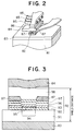
- Figure 2 is an oblique view which shows the structure of magnetic recording head in the magnetic recording system of Example 1.
- Figure 3 is a schematic view which shows the sectional structure of magnetoresistive sensor of the magnetic recording head in the magnetic recording system of Example 1.
- Figure 4 is an oblique view which shows the structure of magnetic recording medium in the magnetic recording system of Example 1.
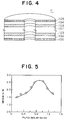
- Figure 5 is a characteristic curve which shows the relation between the molar ratio of Pt to Co in the magnetic layer of the magnetic recording medium and the medium S/N of the magnetic recording medium of Example 1.
- Figure 6 is a characteristic curve which shows the relation between the molar ratio of silicon oxide to Co in the magnetic layer of the magnetic recording medium and the normalized noise of the magnetic recording medium of Example 1.
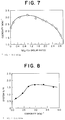
- Figure 7 is a characteristic curve which shows the relation between the molar ratio of silicon oxide to Co in the magnetic layer of the magnetic recording medium and the coercivity of the magnetic recording medium of Example 1.
- Figure 8 is a characteristic curve which shows the relation between the coercivity and the system S/N.
- Figure 9 is a block diagram of an apparatus for measuring jitter.
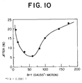
- Figure 10 is a characteristic curve which shows the relation between (Br·t) and jitter.
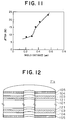
- Figure 11 is a characteristic curve which shows the relation between shield distance and jitter.
- Figure 12 is an oblique view which shows the structure of the magnetic recording medium in the magnetic recording system of Example 2.
- Figure 13 is a schematic view which shows the sectional structure of magnetoresistive sensor of the magnetic recording head in the magnetic recording system of Example 4.
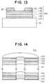
- Figure 14 is an oblique view which shows the structure of the magnetic recording medium in the magnetic recording system of Example 5.
- Figure 15 is an oblique view which shows the structure of the magnetic recording medium in the magnetic recording system of Example 6.
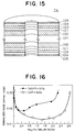
- Figure 16 is a characteristic curve which shows the relation between the molar ratio of silicon oxide to Co in the magnetic layer of the magnetic recording medium and the normalized noise of the magnetic recording medium of Comparative Example.
- Figure 17 is a characteristic curve which shows the relation between the molar ratio of silicon oxide to Co in the magnetic layer of the magnetic recording medium and the coercivity of the magnetic recording medium of Comparative Example.
- The present invention will be explained in detail by the following examples. These examples do not limit the invention in any manner.
- Figures 1(a) and (b) are schematic plan view and schematic sectional view of
magnetic recording system 70 of Example 1. - The
magnetic recording system 70 hasmagnetic recording medium 71, magnetic recordingmedium driving unit 72 which rotates themagnetic recording medium 71 in the recording direction,magnetic recording head 73 which carries out writing in and reading back from themagnetic recording medium 71, magnetic recordinghead driving unit 74 which drives themagnetic head 73 relatively to themagnetic recording medium 71, and read/writesignal processing part 75 which carries out processing of write signal or read signal. - Figure 2 shows the structure of the
magnetic recording head 73. - The
magnetic recording head 73 is a dual head with inductive head for writing and magnetoresistive (MR) read back recording head. That is, the portion comprising upper recordingmagnetic pole 86 and shield layer-recordingmagnetic pole 84 which holdcoil 85 therebetween acts as a magnetic recording head for writing. The portion comprising the shield layer-recordingmagnetic pole 84 andlower shield layer 83 between which magnetoresistivesensor 82 andelectrode pattern 87 are held acts as a magnetic recording head for read back. The output signal from themagnetoresistive sensor 82 is taken out through theelectrode pattern 87. Thelower shield layer 83 is formed onslider substrate 81. - Figure 3 shows sectional structure of the
magnetoresistive sensor 82. - The
magnetoresistive sensor 82 is provided on thelower shield layer 83 with agap layer 91 intervening between them, and themagnetoresistive sensor 82 includes antiferromagneticdomain stabilizing layer 92 provided on thegap layer 91, thin film magnetoresistiveconductive layer 93 of ferromagnetic material which is made a single domain by the antiferromagneticdomain stabilizing layer 92,non-magnetic layer 95 for cutting off the exchange interaction betweensensor 94 of the thin film magnetoresistiveconductive layer 93 and the antiferromagneticdomain stabilizing layer 92, soft magnetic layer 97 for generating a bias magnetic field for thesensor 94, andhigh resistivity layer 96 for controlling current distribution ratio between the soft magnetic layer 97 and the thin film magnetoresistiveconductive layer 93. - The
magnetic recording head 73 was made in the following manner. - A sintered body mainly composed of aluminum oxide and titanium carbide was used as
slider substrate 81. An Ni-Fe alloy film of 1 µm thick was formed aslower shield layer 83 by sputtering method. - An aluminum oxide film of 100 nm thick was formed as the
gap layer 91 by sputtering method. An NiO layer of 20 nm thick was formed as the antiferromagneticdomain stabilizing layer 92 by sputtering method. An Nb layer of 2 nm thick was formed as thenon-magnetic layer 95 by sputtering method. An Ni-Fe alloy layer of 15 nm thick was formed as the thin film magnetoresistiveconductive layer 93 by sputtering method. A Ta layer of 15 nm thick was formed as thehigh resistivity layer 96 by sputtering method. An Ni-Fe-Nb alloy layer of 20 nm thick was formed as the soft magnetic layer 97 by sputtering method. - A Cu thin film of 100 nm thick was formed as the
electrode pattern 87 by sputtering method. -
Gap layer 98 comprising aluminum oxide of 100 nm thick was formed between theelectrode pattern 87 and the shield layer-recordingmagnetic pole 84 by sputtering method. - An Ni-Fe alloy layer of 1 µm thick was formed as soft the shield layer-recording
magnetic pole 84 by sputtering method. - A Cu film of 3 µm thick was formed as
coil 85 by sputtering method. - An Ni-Fe alloy layer of 3 µm thick was formed as the upper recording
magnetic pole 86 by sputtering method. - A gap layer comprising aluminum oxide of 300 nm thick was also formed between the shield layer-recording
magnetic pole 84 and the upper recordingmagnetic pole 86 by sputtering method. - Figure 4 shows a sectional structure of the
magnetic recording medium 71. - The
magnetic recording medium 71 comprisessubstrate 101 of a chemically reinforced glass,magnetic layer 103 of Co-Pt magnetic material containing silicon oxide,protective carbon layer 104, and adsorptive perfluoroalkylpolyether lubricant layer 105. - The
magnetic recording medium 71 was made in the following manner. -
Magnetic layer 103 having a thickness of 25 nm and made of a Co-Pt magnetic material containing silicon oxide was formed on a disk-like glass substrate 101 of 50.8 mm (2.5 inches) in diameter and 0.4 mm thick by RF magnetron sputtering method under the deposition conditions of substrate temperature: room temperature, Ar gas pressure: 15 mTorr and making power density: 5 W per 1 cm2. Then,protective carbon layer 104 of 10-30 nm thick was formed on themagnetic layer 103 by DC magnetron sputtering method under the deposition conditions of substrate temperature: 150°C, Ar gas pressure: 5 mTorr and making power density: 3 W per 1 cm2. Thereafter, polystyrene particles were electrostatically coated on the surface of theprotective layer 104, followed by subjecting to plasma etching of 15 nm with using the polystyrene particle coat as a mask to form micro unevenness on the surface of theprotective layer 104. Finally, an adsorptive perfluoroalkylpolyether lubricant layer 105 of 2-20 nm thick was formed on theprotective layer 104 by dipping method. - Figure 5 shows the relation between the molar ratio of Pt to Co in the Co-Pt magnetic material and the medium S/N at a recording density of 1 gigabit per 1 square inch. The molar ratio of silicon oxide to Co was 0.8.
- When the molar ratio of Pt to Co was 0.6-1.2, the medium S/N could be 2.0 or more.
- Figure 6 shows the relation between the molar ratio of silicon oxide to Co in the Co-Pt magnetic material and the normalized noise. The molar ratio of Pt to Co was about 0.67 (60 at% Co-40 at% Pt).
- When the molar ratio of silicon oxide to Co was 0.1-2.8, the normalized noise could be 0.025 or less. Especially, when the molar ratio of silicon oxide to Co was 0.5-2.4, the normalized noise could be 0.016 or less.
- Figure 7 shows the relation between the molar ratio of silicon oxide to Co in the Co-Pt magnetic material and the coercivity. The molar ratio of Pt to Co was about 0.67.
- When the molar ratio of silicon oxide to Co was 0.1 or more, the coercivity could be made to 2.4 kOe or more. Especially, when the molar ratio of silicon oxide to Co was 0.5-1.4, a coercivity of 239 kA/m (3.0 kOe) or more could be obtained and this is preferred.
- As shown in Figure 8, when the coercivity was less than 191 kA/m (2.4 kOe), the system S/N was lower than 1 and the noise was greater than the signal. Thus, it is necessary that the coercivity be 191 kA/m (2.4 kOe) or more.
- Figure 8 is a graph prepared by plotting against each coercivity the maximum system S/N obtained by examining the system S/N using the media different in Br·t.
- On the other hand, when the molar ratio of silicon oxide to Co was higher than 2.8, sufficient output was not obtained.
- Therefore, the molar ratio of silicon oxide to Co is preferably 0.1-2.8.
- As shown in Figure 9, the read output from
magnetic recording head 73 was pulsed by low-pass filter 51, differential circuit 52 andpulsing circuit 53, fluctuation of pulse interval, δ, was analyzed byjitter meter 54, and the ratio of standard deviation, σ, of pulse interval, δ, to the average value of the pulse interval, δ, was measured as jitter. - Figure 10 shows the relation between the product (Br·t) of residual magnetic flux density, Br, measured by applying a magnetic field in the relative running direction of
magnetic recording head 73 in respect tomagnetic recording medium 71 at the time of recording and magnetic layer thickness, t, of themagnetic recording medium 71 and the jitter of output signal when high density signals of a constant frequency was written and read back. - When Br·t was in the range of 0.001 to 0.01 T (10-100 gauss)·micron, jitter was less than about 15%, and discrimination of bit could be satisfactorily made.
- Figure 11 shows the relation between the distance (shield distance) between the
lower shield layer 83 and the shield layer-recordingmagnetic pole 84 and the jitter. - When the shield distance was less than 0.35 µm, jitter was less than about 15% and the bit could be satisfactorily discriminated.
- The write/read characteristics of
magnetic recording system 70 havingmagnetic recording medium 71 in which the molar ratio of Pt to Co inmagnetic layer 103 was 0.67 (60 at% Co-40 at% Pt) and the molar ratio of silicon oxide to Co was about 0.9 were evaluated under the conditions of head flying height: 30 nm, linear recording density: 210 kBPI, and track density: 9.6 kTPI. - As a result, the system S/N was 1.8. This value was higher about 30% than that obtained when 73 at% Co-15 at% Cr-12 at% Pt was used in place of 60 at% Co-40 at% Pt as the magnetic material.
- Moreover, information of 2 gigabits per 1 square inch could be written and read by subjecting the input signal into the
magnetic recording head 73 to 8-9 code modulation processing and subjecting the output signal to maximum likelihood decoding processing. - The number of bit error after conducting head seek test of 50,000 times from inner periphery to outer periphery was less than 10 bits/face and a mean time between failures MTBF of 150,000 hours could be attained.
- A permanent magnet film bias layer may be used in place of the soft magnetic layer 97 of the
magnetoresistive sensor 82. - Ti, Si, Si-C, carbon, crystallized glass, ceramics, etc. may be used as the material of
substrate 101 of themagnetic recording medium 71. - As the material of
protective layer 104 of themagnetic recording medium 71, there may be used carbides such as tungsten carbide and (W-Mo)-C, nitrides such as (Zr-Nb)-N and silicon nitride, oxides such as silicon dioxide and zirconia, and, furthermore, boron, boron carbide, molybdenum disulfide, Rh, etc. It is preferred to provide theprotective layer 104 and thelubricant layer 105 because sliding resistance and corrosion resistance can be improved. - Furthermore, when micro unevenness is formed on the surface of the
protective layer 104 by plasma etching using a fine mask or the like, or heterogeneous projections are produced on the surface of the protective layer using a target of compound or mixture, or unevenness is formed on the surface by heat treatment, contact area between themagnetic recording head 73 and themagnetic recording medium 71 can be reduced and the problem of themagnetic recording head 73 adhering to the surface of themagnetic recording medium 71 at the time of CSS (contact start stop) operation can be avoided. -
Magnetic recording medium 71a having the structure shown in Figure 12 was used in the magnetic recording system having the same construction as of Example 1. - This
magnetic recording medium 71a had the same structure as of themagnetic recording medium 71 of Example 1, except thatunderlayer 121 was additionally provided and the material of themagnetic layer 103 was changed. - The
underlayer 121 was formed in the following manner. -
Underlayer 121 of Cr having a thickness of 15 nm was formed on a disk-like glass substrate 101 of 50.8 mm (2.5 inches) in diameter and 0.4 mm in thickness by DC magnetron sputtering method under the deposition conditions of substrate temperature: room temperature, Ar gas pressure: 6.666 mhPa (5 mTorr) and making power density: 7 W per 1 cm2. - Ti, V, Ge, Zr, Nb, Mo, Ta, W, and Ni-P may be used as the material of
underlayer 121. - The material of
magnetic layer 103 was 52 at% Co-48 at% Pt to which silicon oxide, aluminum oxide, tantalum oxide, yttrium oxide or titanium oxide was added. - Table 1 shows composition of the
magnetic recording medium 71a, magnetic properties and normalized noise. As a comparative example, results obtained when 73 at% Co-15 at% Cr-12 at% Pt was used in place of 52 at% Co-48 at% Pt are also shown in Table 1. - In all of the
magnetic recording media 71a of Example 2, high coercivity and low normalized noise were obtained. - On the other hand, the coercivity was low and the normalized noise was high in the comparative example where 73 at% Co-15 at% Cr-12 at% Pt was used.
- The write/read characteristics of magnetic recording system having
magnetic recording medium 71a of Sample No.14 shown in Table 1 were evaluated under the conditions of head flying height: 26 nm, linear recording density: 210 kBPI, and track density: 9.6 kTPI. - As a result, the system S/N was 1.8.
- Moreover, information of 2 gigabits per 6.451 cm2 (1 square inch) could be written and read by subjecting the input signals into the
magnetic recording head 73 to 8-9 code modulation processing and subjecting the output signals to maximum likelihood decoding processing. - The number of bit errors after conducting head seek test of 50,000 times from inner periphery to outer periphery was less than 10 bits/face and a mean time between failures MTBF of 150,000 hours could be attained.
- In the conventional magnetic recording medium, the underlayer is provided for controlling orientation of the magnetic layer while in the magnetic recording medium of the present invention, it is provided for controlling crystal grain size and improvement of adhesion to the substrate and corrosion resistance.
Table 1 Sample No. Magnetic material Oxide Pt/Co Molar ratio MOx/Co Molar ratio Hc (kOe) Br·t (Gµm)* Normalized noise (µVrms/µVpp) 11 Co-48 at% Pt Silicon oxide 0.92 1.05 3.08 87 0.013 12 Co-48 at% Pt Aluminum oxide 0.92 1.01 2.83 91 0.015 13 Co-48 at% Pt Tantalium oxide 0.92 1.07 2.72 84 0.016 14 Co-48 at% Pt Yttrium oxide 0.92 1.01 2.68 83 0.017 15 Co-48 at% Pt Titanium oxide 0.92 1.03 2.92 89 0.014 Comparative Sample Co-15 at% Cr Silicon oxide 0.16 1.05 2.05 88 0.021 -12 at% Pt *10 000 G= 1 T - Silicon nitride, boron nitride or aluminum nitride was added in place of the oxide as the non-magnetic compound to the magnetic layer of the
magnetic recording medium 71a in Example 2. - Table 2 shows composition of the magnetic recording medium, magnetic properties and normalized noise. As a comparative example, results obtained when 73 at% Co-15 at% Cr-12 at% Pt was used in place of 52 at% Co-48 at% Pt are also shown in Table 2.
- In all of the magnetic recording media of Example 3, high coercivity and low normalized noise were obtained.
- On the other hand, the coercivity was low and the normalized noise was high in the comparative example where 73 at% Co-15 at% Cr-12 at% Pt was used.
- The write/read characteristics of the magnetic recording system having the magnetic recording medium of Sample No.21 shown in Table 2 were evaluated under the conditions of head flying height: 26 nm, linear recording density: 210 kBPI, and track density: 9.6 kTPI.
- As a result, the system S/N was 1.8.
- Moreover, information of 2 gigabits per 1 square inch could be written and read by subjecting the input signal into the
magnetic recording head 73 to 8-9 code modulation processing and subjecting the output signal to maximum likelihood decoding processing. - The number of bit errors after conducting head seek test of 50,000 times from inner periphery to outer periphery was less than 10 bits/face and a mean time between failures MTBF of 150,000 hours could be attained.
Table 2 Sample No. Magnetic material Nitride Pt/Co Molar ratio LNy/Co Molar ratio Hc (kOe)* Br·t (Gµm)** Normalized noise (µVrms/µVpp) 21 Co-48 at% Pt Silicon nitride 0.92 1.03 2.91 86 0.014 22 Co-48 at% Pt Boron nitride 0.92 1.01 2.86 89 0.015 23 Co-48 at% Pt Aluminum nitride 0.92 1.05 2.72 91 0.017 Comparative Sample Co-15 at% Cr Silicon nitride 0.16 1.01 1.86 87 0.024 -12 at% Pt *1 k0e = 79.6 kA/m **1 G = 0.0001 T - In the magnetic recording system having the same construction as of Example 1, magnetoresistive sensor 82a shown in Figure 13 was used in place of the magnetoresistive sensor 82 (Figure 3) of magnetic recording head for reading. Moreover, an Fe-Co-Ni alloy film formed by plating method was used as the upper recording
magnetic pole 86 of the magnetic recording head for writing. In addition, the magnetic recording medium was changed. - The magnetoresistive sensor 82a shown in Figure 13 was a magnetoresistive sensor which utilizes resistivity change occurring due to the change in the relative magnetization directions between the two
magnetic layers -
Buffer layer 131 was a Ti layer of 2 nm thick. The firstmagnetic layer 132 was a 80 at% Ni-20 at% Fe alloy layer of 3 nm thick. The non-magnetic layer 133 was a Cu layer of 1.5 nm thick. The secondmagnetic layer 134 was a 80 at% Ni-20 at% Fe alloy layer of 3 nm thick. Antiferromagnetic layer 135 was a 50 at% Fe-50 at% Mn alloy layer of 5 nm thick. - These layers were all formed by sputtering method.
- In this magnetoresistive sensor 82a, the magnetization of the second
magnetic layer 134 was fixed to one direction by the exchange bias magnetic field from the antiferromagnetic layer 135 and the magnetization direction of the firstmagnetic layer 132 changed by the leakage field from themagnetic recording medium 71 to cause change in resistivity. - By using Ti as the
buffer layer 131, the crystal lattice plane {111} of the firstmagnetic layer 132 and the secondmagnetic layer 134 was orientated so that the plane was in parallel to the film surface. Thus, the exchange interaction between themagnetic layers magnetoresistive sensor 82 of Example 1 was obtained. - Furthermore, by using Fe-Co-Ni alloy film formed by plating method as the upper recording
magnetic pole 86, the saturated magnetic flux density increased to 1.6 T (16000 gausses) and the over writing characteristics could be improved by about 6 dB as compared with those of Example 3. - The magnetic recording medium had the structure obtained by forming the
magnetic layer 103 of 25 nm thick composed of 52 at% Co-48 at% Pt containing silicon oxide at a molar ratio of 1.2 (molar ratio of the silicon oxide to Co) on a carbon substrate having a diameter of 33.02 mm (1.3 inch), a thickness of 0.4 mm and a surface roughness of 1 nm under the same conditions as in Example 1, forming thereonprotective carbon layer 104 of 20 nm thick, subjecting the surface to electrostatic coating with polystyrene particles, carrying out plasma etching of 13 nm using the coat as a mask to form micro unevenness on the surface of theprotective layer 104, and, finally, forming an adsorptive perfluoroalkylpolyether lubricant layer 105 on theprotective layer 104 by dipping method. - The coercivity measured by applying a magnetic field in the circumferential direction of the disk of this magnetic recording medium was 216 kA/m (2.71 kOe) and the product of residual magnetic flux density, Br, and the total magnetic layer thickness, t, (Br·t) was 0.0062 T (62 gauss)·micron.
- The write/read characteristics of the magnetic recording system of Example 4 were evaluated under the conditions of head flying height: 25 nm, linear recording density: 260 kBPI, and track density: 11.6 kTPI.
- As a result, the system S/N was 1.5.
- Information of 3 gigabits per 1 square inch could be written and read back by subjecting the input signal into the
magnetic recording head 73 to 8-9 code modulation processing and subjecting the output signal to maximum likelihood decode processing. - The number of bit errors after conducting head seek test of 50,000 times from inner periphery to outer periphery was less than 10 bits/face and a mean time between failures (MTBF) of 150,000 hours could be attained.
- The thickness of the non-magnetic layer 133 in the magnetoresistive sensor 82a is preferably 1.5 nm or more, but if it is too thick, the over writing characteristics are deteriorated since the distance between the magnetic recording head for writing and the lowermost
magnetic layer 132 is great. Especially, when the non-magnetic layer has a two-layer structure, the over writing characteristics are deteriorated because the non-magnetic layer becomes thick. In order to solve this problem, it is effective to use as the recording magnetic pole of the magnetic recording head for writing a soft magnetic thin film of an Fe-Co-Ni alloy, an Fe-Si alloy or the like which has a higher saturated magnetic flux density than the conventional Ni-Fe alloys. Especially, good results can be obtained when a soft magnetic thin film having a saturated magnetic flux density of at least 1.5 T (15000 gausses) is used. - As shown by
magnetic recording medium 71b in Figure 14, the medium may have a structure comprising asubstrate 101 of Al-Mg alloy and, formed on both sides thereof, non-magnetic platedlayer 102 of Ni-P, Ni-W-P or the like,magnetic layer 103,protective layer 104 andlubricant layer 105. - As shown by
magnetic recording medium 71c in Figure 15, the medium may have a structure comprising asubstrate 101 of Al-Mg alloy and, formed on both sides thereof, non-magnetic platedlayer 102 of Ni-P, Ni-W-P or the like,underlayer 121,magnetic layer 103,protective layer 104 andlubricant layer 105. - Relations between the molar ratio of silicon oxide to Co and the normalized noise and between the molar ratio of silicon oxide to Co and the coercivity (Hc) when 73 at% Co-15 at% Cr-12 at% Pt was used as the magnetic material of the
magnetic layer 103 of themagnetic recording medium 71 of Example 1 were examined. - As shown by a broken line in Figure 16, when the molar ratio of silicon oxide to Co was more than 0.1, the normalized noise was greater than that of the
magnetic recording medium 71 of Example 1 shown by a solid line. - Furthermore, as shown by a broken line in Figure 17, when the molar ratio of silicon oxide to Co was more than 0.2, the coercivity was lower than that of the
magnetic recording medium 71 of Example 1 shown by a solid line. - In place of adding the oxide or nitride, a mixed gas comprising an Ar sputtering gas used for film deposition by sputtering and oxygen or nitrogen was used.
- The coercivity could be increased to some extent. However, the effect to reduce the normalized noise was small and it was difficult to realize a recording density of higher than 1 gigabit per 6.451 cm2 (1 square inch).
- It is considered that this is because when an oxygen or nitrogen mixed gas is used, oxygen or nitrogen is taken into not only crystal grain boundary, but also crystal grains and this damages the crystallinity.
- According to the magnetic recording system and the magnetic recording medium of the present invention, a high S/N and a low bit error rate can be obtained, and, therefore, a mean time between failures of more than 150,000 hours can be realized with a high recording density of at least 1 gigabit per 6.451 cm2 (1 square inch).
Claims (20)
- A magnetic recording system having a magnetic recording medium (71) and a magnetic recording head (73), said magnetic recording medium (71) comprising a substrate (101) and a magnetic layer (103) formed on the substrate (101) directly or indirectly with an underlayer (121) intervening between the magnetic layer (103) and the substrate (101) and said magnetic recording head (73) carrying out writing in and reading back from the magnetic recording medium (71), characterized in that the magnetic layer (103) of the magnetic recording medium (71) comprises a mixture of at least one non-magnetic compound selected from the group consisting of oxides represented by the formula MOx (wherein M represents at least one element selected from the group consisting of Si, Al, Ta, Y and Ti, and x represents a numerical value of from about 1 to about 2.5) and a magnetic material of an alloy comprising Co and Pt as main components, the molar ratio of Pt to Co in the magnetic layer (103) falls within the range of from 0.6 to 1.2, the molar ratio of the non-magnetic compound to Co falls within the range of from 0.1 to 2.8, and the magnetic recording head (73) includes a magnetoresistive read back magnetic recording head.
- The magnetic recording system according to claim 1, wherein the alloy consists essentially of Co and Pt.
- The magnetic recording system according to claim 1, wherein the magnetoresistive read back magnetic recording head (73) has two shield layers (83, 84) and a magnetoresistive sensor (82) formed between the shield layers (83, 84) and the distance between the two shield layers is 0.35 µm or less.
- The magnetic recording system according to claim 1, wherein the product (Br·t) of a residual magnetic flux density, Br, measured by applying a magnetic field in the relative running direction of the magnetic recording head (73) in respect to the magnetic recording medium (71) at the time of recording and a thickness, t, of the magnetic layer (103) of the magnetic recording medium (71) falls within the range of from 0.001 to 0.01 T (10 to 100 gauss)·micron.
- The magnetic recording system according to claim 1, wherein the coercivity of the magnetic recording medium (71) measured by applying a magnetic field in the relative running direction of the magnetic recording head (73) in respect to the magnetic recording medium (71) at the time of recording is 191 kA/m (2.4 kOe) or more.
- The magnetic recording system according to claim 1, wherein the magnetoresistive read back magnetic recording head (73) has a magnetoresistive sensor (82) including a plurality of magnetic layers (93, 97) and non-magnetic layers (95, 96) provided between the magnetic layers (93, 97), said magnetic layers (93, 97) causing a great change in resistivity due to relative change of mutual magnetization directions by external magnetic field.
- A magnetic recording system having a magnetic recording medium (71) and a magnetic recording head (73), said magnetic recording medium (71) comprising a substrate (101) and a magnetic layer (103) formed on the substrate (101) directly or indirectly with an underlayer (121; 102) intervening between the magnetic layer (103) and the substrate (101) and said magnetic recording head (73) carrying out writing in and reading back from the magnetic recording medium (71), characterized in that the magnetic layer (103) of the magnetic recording medium (71) comprises a mixture of at least one non-magnetic compound selected from the group consisting of nitrides represented by the formula LNy (wherein L represents at least one element selected from the group consisting of Si, B and Al and y represents a numerical value of from about 1 to about 1.3) and a magnetic material of an alloy comprising Co and Pt as main components, the molar ratio of Pt to Co in the magnetic layer (103) falls within the range of from 0.6 to 1.2, the molar ratio of the non-magnetic compound to Co falls within the range of from 0.1 to 2.8, and the magnetic recording head (73) includes a magnetoresistive read back magnetic recording head.
- The magnetic recording system according to claim 7, wherein the alloy consists essentially of Co and Pt.
- The magnetic recording system according to claim 7, wherein the magnetoresistive read back magnetic recording head (73) has two shield layers (83, 84) and a magnetoresistive sensor (82) formed between the shield layers (83, 84) and the distance between the two shield layers is 0.35 µm or less.
- The magnetic recording system according to claim 7, wherein the product (Br·t) of a residual magnetic flux density, Br, measured by applying a magnetic field in the relative running direction of the magnetic recording head (73) in respect to the magnetic recording medium (71) at the time of recording and a thickness, t, of the magnetic layer (103) of the magnetic recording medium (71) falls within the range of from 0.001 to 0.01 T (10 to 100 gauss)·micron.
- The magnetic recording system according to claim 7, wherein the coercivity of the magnetic recording medium measured by applying a magnetic field in the relative running direction of the magnetic recording head (73) in respect to the magnetic recording medium (71) at the time of recording is 191 kA/m (2.4 kOe) or more.
- The magnetic recording system according to claim 7, wherein the magnetoresistive read back magnetic recording head (73) has a magnetoresistive sensor (82) including a plurality of magnetic layers (93, 97) and non-magnetic layers (95, 96) provided between the magnetic layers (93, 97), said magnetic layers (93, 97) causing a great change in resistivity due to relative change of mutual magnetization directions by external magnetic field.
- The magnetic recording system according to claim 1, wherein the molar ratio of the non-magnetic compound to Co in the magnetic layer (103) of the magnetic recording medium (71) falls within the range of from 0.5 to 2.4.
- The magnetic recording system according to claim 7, wherein the molar ratio of the non-magnetic compound to Co in the magnetic layer (103) of the magnetic recording medium (71) falls within the range of from 0.5 to 2.4.
- A magnetic recording medium comprising a substrate (101) and a magnetic layer (103) formed on the substrate (101) directly or indirectly with an underlayer (121; 102) intervening between the magnetic layer (103) and the substrate (101), characterized in that the magnetic layer (103) comprises a mixture of at least one non-magnetic compound selected from the group consisting of oxides represented by the formula MOx (wherein M represents at least one element selected from the group consisting of Si, Al, Ta, Y and Ti, and x represents a numerical value of from about 1 to about 2.5) and a magnetic material of an alloy comprising Co and Pt as main components, the molar ratio of Pt to Co in the magnetic layer (103) falls within the range of from 0.6 to 1.2, and the molar ratio of the non-magnetic compound to Co falls within the range of from 0.1 to 2.8.
- The magnetic recording medium according to claim 15, wherein the alloy consists essentially of Co and Pt.
- A magnetic recording medium comprising a substrate (101) and a magnetic layer (103) formed on the substrate (101) directly or indirectly with an underlayer (121; 102) intervening between the substrate (101) and the magnetic layer (103), characterized in that the magnetic layer (103) comprises a mixture of at least one non-magnetic compound selected from the group consisting of nitrides represented by the formula LNy (wherein L represents at least one element selected from the group consisting of Si, B and Al and y represents a numerical value of from about 1 to about 1.3) and a magnetic material of an alloy comprising Co and Pt as main components, the molar ratio of Pt to Co in the magnetic layer (103) falls within the range of from 0.6 to 1.2, and the molar ratio of the non-magnetic compound to Co falls within the range of from 0.1 to 2.8.
- The magnetic recording medium according to claim 17, wherein the alloy consists essentially of Co and Pt.
- The magnetic recording medium according to claim 15, wherein the molar ratio of the non-magnetic compound to Co in the magnetic layer (103) falls within the range of from 0.5 to 2.4.
- The magnetic recording medium according to claim 17, wherein the molar ratio of the non-magnetic compound to Co in the magnetic layer (103) falls within the range of from 0.5 to 2.4.
Applications Claiming Priority (2)
| Application Number | Priority Date | Filing Date | Title |
|---|---|---|---|
| JP16052195A JP3448698B2 (en) | 1995-06-27 | 1995-06-27 | Magnetic storage device and magnetic recording medium |
| JP160521/95 | 1995-06-27 |
Publications (3)
| Publication Number | Publication Date |
|---|---|
| EP0751502A2 true EP0751502A2 (en) | 1997-01-02 |
| EP0751502A3 EP0751502A3 (en) | 1997-01-08 |
| EP0751502B1 EP0751502B1 (en) | 2006-05-24 |
Family
ID=15716762
Family Applications (1)
| Application Number | Title | Priority Date | Filing Date |
|---|---|---|---|
| EP96110302A Expired - Lifetime EP0751502B1 (en) | 1995-06-27 | 1996-06-26 | Magnetic recording system and magnetic recording medium used therefor |
Country Status (6)
| Country | Link |
|---|---|
| US (2) | US5919581A (en) |
| EP (1) | EP0751502B1 (en) |
| JP (1) | JP3448698B2 (en) |
| CN (1) | CN1082219C (en) |
| DE (1) | DE69636155T2 (en) |
| SG (1) | SG42420A1 (en) |
Cited By (2)
| Publication number | Priority date | Publication date | Assignee | Title |
|---|---|---|---|---|
| US6597654B2 (en) | 1999-05-21 | 2003-07-22 | Matsushita Electric Industrial Co., Ltd. | Recordable optical disk |
| EP1345212A2 (en) * | 2002-03-13 | 2003-09-17 | Fuji Photo Film Co., Ltd. | Magnetic recording medium |
Families Citing this family (20)
| Publication number | Priority date | Publication date | Assignee | Title |
|---|---|---|---|---|
| JP3448698B2 (en) * | 1995-06-27 | 2003-09-22 | 株式会社日立製作所 | Magnetic storage device and magnetic recording medium |
| JPH10275325A (en) * | 1997-03-28 | 1998-10-13 | Fuji Photo Film Co Ltd | Disk-shaped magnetic recording medium |
| US6221508B1 (en) * | 1997-12-09 | 2001-04-24 | Hitachi, Ltd. | Magnetic recording media |
| EP1264851B1 (en) * | 2000-02-07 | 2006-07-19 | Nagoya Oilchemical Co., Ltd. | Resin composition, molding material, and molded object |
| JP2002133645A (en) * | 2000-10-20 | 2002-05-10 | Fuji Electric Co Ltd | Magnetic recording medium and its manufacturing method |
| US6714387B1 (en) * | 2001-01-08 | 2004-03-30 | Headway Technologies, Inc. | Spin valve head with reduced element gap |
| US6577477B1 (en) | 2001-02-01 | 2003-06-10 | Headway Technologies, Inc. | Hard magnetic bias configuration for GMR |
| WO2003009280A1 (en) * | 2001-07-11 | 2003-01-30 | Fujitsu Limited | Magnetic recording medium and method for manufacturing the same |
| US20030134151A1 (en) * | 2001-09-14 | 2003-07-17 | Fuji Photo Film Co., Ltd. | Magnetic recording medium |
| JP3773104B2 (en) * | 2001-12-11 | 2006-05-10 | 富士電機デバイステクノロジー株式会社 | Magnetic recording medium and method for manufacturing the same |
| US7192664B1 (en) | 2003-06-24 | 2007-03-20 | Seagate Technology Llc | Magnetic alloy containing TiO2 for perpendicular magnetic recording application |
| US20050095421A1 (en) * | 2003-11-03 | 2005-05-05 | Seagate Technology | Magnetic material for non-reactive process of granular perpendicular recording application |
| US7482071B2 (en) * | 2005-05-24 | 2009-01-27 | Hitachi Global Storage Technologies Netherlands B.V. | Perpendicular magnetic recording disk with improved recording layer having high oxygen content |
| US7491452B2 (en) | 2005-08-12 | 2009-02-17 | Hitachi Global Storage Technologies Netherlands B.V. | Perpendicular magnetic recording disk with recording layer containing selected metal oxides and formed on a reduced-thickness exchange-break layer |
| DE102008041727B4 (en) * | 2008-09-01 | 2011-06-16 | Robert Bosch Gmbh | Device and method for stabilizing a lane keeping support system |
| US8685547B2 (en) | 2009-02-19 | 2014-04-01 | Seagate Technology Llc | Magnetic recording media with enhanced writability and thermal stability |
| US8653824B1 (en) * | 2009-12-16 | 2014-02-18 | Western Digital (Fremont), Llc | Delta temperature test method and system |
| US8427775B2 (en) * | 2010-06-30 | 2013-04-23 | HGST Netherlands B.V. | Particle-capturing device including a component configured to provide an additional function within an enclosure exclusive of capturing particles |
| US9142240B2 (en) | 2010-07-30 | 2015-09-22 | Seagate Technology Llc | Apparatus including a perpendicular magnetic recording layer having a convex magnetic anisotropy profile |
| US20160293199A1 (en) * | 2014-04-24 | 2016-10-06 | Fuji Electric Co., Ltd. | Method for manufacturing magnetic recording medium |
Citations (4)
| Publication number | Priority date | Publication date | Assignee | Title |
|---|---|---|---|---|
| EP0216062A1 (en) * | 1985-08-15 | 1987-04-01 | International Business Machines Corporation | Magnetoresistive read transducer assembly |
| DE4021970A1 (en) * | 1989-07-10 | 1991-01-24 | Toshiba Kawasaki Kk | High density magnetic recording layer - uses an alloy of cobalt, platinum and chromium which is sputtered in an ambient containing oxygen and/or nitrogen |
| EP0531035A1 (en) * | 1991-09-06 | 1993-03-10 | International Business Machines Corporation | Magnetic recording medium |
| EP0538823A2 (en) * | 1991-10-22 | 1993-04-28 | Sony Corporation | Perpendicular magnetic recording and perpendicular magnetic reproducing apparatus |
Family Cites Families (12)
| Publication number | Priority date | Publication date | Assignee | Title |
|---|---|---|---|---|
| US4438066A (en) * | 1981-06-30 | 1984-03-20 | International Business Machines Corporation | Zero to low magnetostriction, high coercivity, polycrystalline, Co-Pt magnetic recording media |
| US4988578A (en) * | 1986-03-10 | 1991-01-29 | Komag, Inc. | Method for manufacturing a thin film magnetic recording medium |
| US5143794A (en) * | 1988-08-10 | 1992-09-01 | Hitachi, Ltd. | Magnetic recording media for longitudinal recording, process for producing the same and magnetic memory apparatus |
| US4902583A (en) * | 1989-03-06 | 1990-02-20 | Brucker Charles F | Thick deposited cobalt platinum magnetic film and method of fabrication thereof |
| JPH03222113A (en) * | 1990-01-25 | 1991-10-01 | Fuji Photo Film Co Ltd | Magnetic recording medium |
| JPH04356721A (en) * | 1991-03-28 | 1992-12-10 | Fuji Photo Film Co Ltd | Magnetic recording medium |
| JPH05197944A (en) * | 1991-10-02 | 1993-08-06 | A G Technol Kk | Magnetic recording medium and its production |
| US5605733A (en) * | 1992-01-22 | 1997-02-25 | Hitachi, Ltd. | Magnetic recording medium, method for its production, and system for its use |
| US5478661A (en) * | 1993-04-01 | 1995-12-26 | Ag Technology Co., Ltd. | Magnetic recording medium and method for its production |
| US5631094A (en) * | 1994-01-28 | 1997-05-20 | Komag, Incorporated | Magnetic alloy for improved corrosion resistance and magnetic performance |
| US5583727A (en) * | 1995-05-15 | 1996-12-10 | International Business Machines Corporation | Multiple data layer magnetic recording data storage system with digital magnetoresistive read sensor |
| JP3448698B2 (en) * | 1995-06-27 | 2003-09-22 | 株式会社日立製作所 | Magnetic storage device and magnetic recording medium |
-
1995
- 1995-06-27 JP JP16052195A patent/JP3448698B2/en not_active Expired - Fee Related
-
1996
- 1996-06-24 SG SG1996010132A patent/SG42420A1/en unknown
- 1996-06-25 US US08/670,121 patent/US5919581A/en not_active Expired - Lifetime
- 1996-06-26 DE DE69636155T patent/DE69636155T2/en not_active Expired - Fee Related
- 1996-06-26 EP EP96110302A patent/EP0751502B1/en not_active Expired - Lifetime
- 1996-06-27 CN CN96110204A patent/CN1082219C/en not_active Expired - Fee Related
-
1999
- 1999-05-25 US US09/317,852 patent/US6177208B1/en not_active Expired - Fee Related
Patent Citations (4)
| Publication number | Priority date | Publication date | Assignee | Title |
|---|---|---|---|---|
| EP0216062A1 (en) * | 1985-08-15 | 1987-04-01 | International Business Machines Corporation | Magnetoresistive read transducer assembly |
| DE4021970A1 (en) * | 1989-07-10 | 1991-01-24 | Toshiba Kawasaki Kk | High density magnetic recording layer - uses an alloy of cobalt, platinum and chromium which is sputtered in an ambient containing oxygen and/or nitrogen |
| EP0531035A1 (en) * | 1991-09-06 | 1993-03-10 | International Business Machines Corporation | Magnetic recording medium |
| EP0538823A2 (en) * | 1991-10-22 | 1993-04-28 | Sony Corporation | Perpendicular magnetic recording and perpendicular magnetic reproducing apparatus |
Cited By (4)
| Publication number | Priority date | Publication date | Assignee | Title |
|---|---|---|---|---|
| US6597654B2 (en) | 1999-05-21 | 2003-07-22 | Matsushita Electric Industrial Co., Ltd. | Recordable optical disk |
| EP1345212A2 (en) * | 2002-03-13 | 2003-09-17 | Fuji Photo Film Co., Ltd. | Magnetic recording medium |
| EP1345212A3 (en) * | 2002-03-13 | 2003-12-03 | Fuji Photo Film Co., Ltd. | Magnetic recording medium |
| US6869688B2 (en) | 2002-03-13 | 2005-03-22 | Fuji Photo Film Co., Ltd. | Magnetic recording medium |
Also Published As
| Publication number | Publication date |
|---|---|
| CN1082219C (en) | 2002-04-03 |
| SG42420A1 (en) | 1997-08-15 |
| US6177208B1 (en) | 2001-01-23 |
| EP0751502A3 (en) | 1997-01-08 |
| JPH0916935A (en) | 1997-01-17 |
| JP3448698B2 (en) | 2003-09-22 |
| DE69636155T2 (en) | 2007-06-06 |
| US5919581A (en) | 1999-07-06 |
| DE69636155D1 (en) | 2006-06-29 |
| EP0751502B1 (en) | 2006-05-24 |
| CN1146589A (en) | 1997-04-02 |
Similar Documents
| Publication | Publication Date | Title |
|---|---|---|
| EP0751502B1 (en) | Magnetic recording system and magnetic recording medium used therefor | |
| US7056604B2 (en) | Magnetic recording media and magnetic recording system using the same | |
| US6221508B1 (en) | Magnetic recording media | |
| EP0725391A2 (en) | Magnetic recording medium and magnetic recording system using the same | |
| US6511761B1 (en) | Magnetic recording media and magnetic storage apparatus | |
| US6372367B1 (en) | Magnetic recording medium, method for producing the same and magnetic recording apparatus using the same | |
| KR20080076699A (en) | Vertical magnetic recording medium, manufacturing method therefor, and magnetic recording apparatus | |
| US6432562B1 (en) | Magnetic recording medium with a nialru seedlayer | |
| US6129981A (en) | Magnetic recording medium and magnetic recording disk device | |
| US6815097B2 (en) | Magnetic recording medium | |
| US20020037440A1 (en) | Magnetic recording medium, the manufacturing method and magnetic recording apparatus using the same | |
| US5945190A (en) | Magnetic recording medium and magnetic disk device | |
| EP0809238A2 (en) | Magnetic recording media and magnetic recording system using the same | |
| JP3564707B2 (en) | Magnetic recording media | |
| JP3394108B2 (en) | Magnetic storage device and multilayer magnetic layer magnetic recording medium | |
| JP2918199B2 (en) | Magnetic recording medium and magnetic storage device | |
| JPH10289437A (en) | Magnetic recording medium and magnetic storage device | |
| US6376097B1 (en) | Recording media with a TiW sealing layer | |
| JP2000067423A (en) | Intra-surface magnetic recording medium and magnetic storage using the same | |
| JP2002216341A (en) | Perpendicular magnetic recording medium | |
| JP2000222715A (en) | Magnetic recording medium | |
| JPH0916939A (en) | Multiple magnetic layer magnetic recording medium and magnetic storage device using the same | |
| JP3565103B2 (en) | Magnetic recording device | |
| JP2001110030A (en) | Magnetic recording medium | |
| JP2001006145A (en) | Magnetic recording medium and manufacture of the same and magnetic storage device |
Legal Events
| Date | Code | Title | Description |
|---|---|---|---|
| PUAI | Public reference made under article 153(3) epc to a published international application that has entered the european phase |
Free format text: ORIGINAL CODE: 0009012 |
|
| PUAL | Search report despatched |
Free format text: ORIGINAL CODE: 0009013 |
|
| AK | Designated contracting states |
Kind code of ref document: A2 Designated state(s): DE FR GB |
|
| AK | Designated contracting states |
Kind code of ref document: A3 Designated state(s): DE FR GB |
|
| 17P | Request for examination filed |
Effective date: 19961204 |
|
| 17Q | First examination report despatched |
Effective date: 20000224 |
|
| RAP1 | Party data changed (applicant data changed or rights of an application transferred) |
Owner name: HITACHI GLOBAL STORAGE TECHNOLOGIES JAPAN, LTD. |
|
| GRAP | Despatch of communication of intention to grant a patent |
Free format text: ORIGINAL CODE: EPIDOSNIGR1 |
|
| GRAS | Grant fee paid |
Free format text: ORIGINAL CODE: EPIDOSNIGR3 |
|
| GRAA | (expected) grant |
Free format text: ORIGINAL CODE: 0009210 |
|
| AK | Designated contracting states |
Kind code of ref document: B1 Designated state(s): DE FR GB |
|
| REG | Reference to a national code |
Ref country code: GB Ref legal event code: FG4D |
|
| REF | Corresponds to: |
Ref document number: 69636155 Country of ref document: DE Date of ref document: 20060629 Kind code of ref document: P |
|
| ET | Fr: translation filed | ||
| PLBE | No opposition filed within time limit |
Free format text: ORIGINAL CODE: 0009261 |
|
| STAA | Information on the status of an ep patent application or granted ep patent |
Free format text: STATUS: NO OPPOSITION FILED WITHIN TIME LIMIT |
|
| 26N | No opposition filed |
Effective date: 20070227 |
|
| PGFP | Annual fee paid to national office [announced via postgrant information from national office to epo] |
Ref country code: DE Payment date: 20070606 Year of fee payment: 12 |
|
| PGFP | Annual fee paid to national office [announced via postgrant information from national office to epo] |
Ref country code: GB Payment date: 20070523 Year of fee payment: 12 |
|
| PGFP | Annual fee paid to national office [announced via postgrant information from national office to epo] |
Ref country code: FR Payment date: 20070521 Year of fee payment: 12 |
|
| GBPC | Gb: european patent ceased through non-payment of renewal fee |
Effective date: 20080626 |
|
| REG | Reference to a national code |
Ref country code: FR Ref legal event code: ST Effective date: 20090228 |
|
| PG25 | Lapsed in a contracting state [announced via postgrant information from national office to epo] |
Ref country code: DE Free format text: LAPSE BECAUSE OF NON-PAYMENT OF DUE FEES Effective date: 20090101 |
|
| PG25 | Lapsed in a contracting state [announced via postgrant information from national office to epo] |
Ref country code: GB Free format text: LAPSE BECAUSE OF NON-PAYMENT OF DUE FEES Effective date: 20080626 |
|
| PG25 | Lapsed in a contracting state [announced via postgrant information from national office to epo] |
Ref country code: FR Free format text: LAPSE BECAUSE OF NON-PAYMENT OF DUE FEES Effective date: 20080630 |