EP0751306B1 - Connecting fitting - Google Patents
Connecting fitting Download PDFInfo
- Publication number
- EP0751306B1 EP0751306B1 EP96107429A EP96107429A EP0751306B1 EP 0751306 B1 EP0751306 B1 EP 0751306B1 EP 96107429 A EP96107429 A EP 96107429A EP 96107429 A EP96107429 A EP 96107429A EP 0751306 B1 EP0751306 B1 EP 0751306B1
- Authority
- EP
- European Patent Office
- Prior art keywords
- housing
- connecting fitting
- bolt
- bore
- shaped
- Prior art date
- Legal status (The legal status is an assumption and is not a legal conclusion. Google has not performed a legal analysis and makes no representation as to the accuracy of the status listed.)
- Expired - Lifetime
Links
- 230000000295 complement effect Effects 0.000 claims description 5
- 239000000463 material Substances 0.000 claims description 2
- 238000010079 rubber tapping Methods 0.000 description 8
- 238000005192 partition Methods 0.000 description 4
- 238000004873 anchoring Methods 0.000 description 1
- 230000008602 contraction Effects 0.000 description 1
- 238000002347 injection Methods 0.000 description 1
- 239000007924 injection Substances 0.000 description 1
- 239000002184 metal Substances 0.000 description 1
- 230000000149 penetrating effect Effects 0.000 description 1
Images


Classifications
-
- F—MECHANICAL ENGINEERING; LIGHTING; HEATING; WEAPONS; BLASTING
- F16—ENGINEERING ELEMENTS AND UNITS; GENERAL MEASURES FOR PRODUCING AND MAINTAINING EFFECTIVE FUNCTIONING OF MACHINES OR INSTALLATIONS; THERMAL INSULATION IN GENERAL
- F16B—DEVICES FOR FASTENING OR SECURING CONSTRUCTIONAL ELEMENTS OR MACHINE PARTS TOGETHER, e.g. NAILS, BOLTS, CIRCLIPS, CLAMPS, CLIPS OR WEDGES; JOINTS OR JOINTING
- F16B12/00—Jointing of furniture or the like, e.g. hidden from exterior
- F16B12/10—Jointing of furniture or the like, e.g. hidden from exterior using pegs, bolts, tenons, clamps, clips, or the like
- F16B12/12—Jointing of furniture or the like, e.g. hidden from exterior using pegs, bolts, tenons, clamps, clips, or the like for non-metal furniture parts, e.g. made of wood, of plastics
- F16B12/14—Jointing of furniture or the like, e.g. hidden from exterior using pegs, bolts, tenons, clamps, clips, or the like for non-metal furniture parts, e.g. made of wood, of plastics using threaded bolts or screws
- F16B12/16—Jointing of furniture or the like, e.g. hidden from exterior using pegs, bolts, tenons, clamps, clips, or the like for non-metal furniture parts, e.g. made of wood, of plastics using threaded bolts or screws using self-tapping screws
-
- F—MECHANICAL ENGINEERING; LIGHTING; HEATING; WEAPONS; BLASTING
- F16—ENGINEERING ELEMENTS AND UNITS; GENERAL MEASURES FOR PRODUCING AND MAINTAINING EFFECTIVE FUNCTIONING OF MACHINES OR INSTALLATIONS; THERMAL INSULATION IN GENERAL
- F16B—DEVICES FOR FASTENING OR SECURING CONSTRUCTIONAL ELEMENTS OR MACHINE PARTS TOGETHER, e.g. NAILS, BOLTS, CIRCLIPS, CLAMPS, CLIPS OR WEDGES; JOINTS OR JOINTING
- F16B12/00—Jointing of furniture or the like, e.g. hidden from exterior
- F16B12/06—Non-loosenable joints for metal furniture parts
-
- F—MECHANICAL ENGINEERING; LIGHTING; HEATING; WEAPONS; BLASTING
- F16—ENGINEERING ELEMENTS AND UNITS; GENERAL MEASURES FOR PRODUCING AND MAINTAINING EFFECTIVE FUNCTIONING OF MACHINES OR INSTALLATIONS; THERMAL INSULATION IN GENERAL
- F16B—DEVICES FOR FASTENING OR SECURING CONSTRUCTIONAL ELEMENTS OR MACHINE PARTS TOGETHER, e.g. NAILS, BOLTS, CIRCLIPS, CLAMPS, CLIPS OR WEDGES; JOINTS OR JOINTING
- F16B12/00—Jointing of furniture or the like, e.g. hidden from exterior
- F16B12/10—Jointing of furniture or the like, e.g. hidden from exterior using pegs, bolts, tenons, clamps, clips, or the like
- F16B12/12—Jointing of furniture or the like, e.g. hidden from exterior using pegs, bolts, tenons, clamps, clips, or the like for non-metal furniture parts, e.g. made of wood, of plastics
- F16B12/20—Jointing of furniture or the like, e.g. hidden from exterior using pegs, bolts, tenons, clamps, clips, or the like for non-metal furniture parts, e.g. made of wood, of plastics using clamps, clips, wedges, sliding bolts, or the like
- F16B12/2009—Jointing of furniture or the like, e.g. hidden from exterior using pegs, bolts, tenons, clamps, clips, or the like for non-metal furniture parts, e.g. made of wood, of plastics using clamps, clips, wedges, sliding bolts, or the like actuated by rotary motion
- F16B12/2054—Jointing of furniture or the like, e.g. hidden from exterior using pegs, bolts, tenons, clamps, clips, or the like for non-metal furniture parts, e.g. made of wood, of plastics using clamps, clips, wedges, sliding bolts, or the like actuated by rotary motion with engaging screw threads as securing means for limiting movement
- F16B12/2063—Jointing of furniture or the like, e.g. hidden from exterior using pegs, bolts, tenons, clamps, clips, or the like for non-metal furniture parts, e.g. made of wood, of plastics using clamps, clips, wedges, sliding bolts, or the like actuated by rotary motion with engaging screw threads as securing means for limiting movement with engaging screw threads as tightening means
-
- F—MECHANICAL ENGINEERING; LIGHTING; HEATING; WEAPONS; BLASTING
- F16—ENGINEERING ELEMENTS AND UNITS; GENERAL MEASURES FOR PRODUCING AND MAINTAINING EFFECTIVE FUNCTIONING OF MACHINES OR INSTALLATIONS; THERMAL INSULATION IN GENERAL
- F16B—DEVICES FOR FASTENING OR SECURING CONSTRUCTIONAL ELEMENTS OR MACHINE PARTS TOGETHER, e.g. NAILS, BOLTS, CIRCLIPS, CLAMPS, CLIPS OR WEDGES; JOINTS OR JOINTING
- F16B12/00—Jointing of furniture or the like, e.g. hidden from exterior
- F16B12/10—Jointing of furniture or the like, e.g. hidden from exterior using pegs, bolts, tenons, clamps, clips, or the like
- F16B2012/103—Sleeves or dowels for connection fittings
-
- F—MECHANICAL ENGINEERING; LIGHTING; HEATING; WEAPONS; BLASTING
- F16—ENGINEERING ELEMENTS AND UNITS; GENERAL MEASURES FOR PRODUCING AND MAINTAINING EFFECTIVE FUNCTIONING OF MACHINES OR INSTALLATIONS; THERMAL INSULATION IN GENERAL
- F16B—DEVICES FOR FASTENING OR SECURING CONSTRUCTIONAL ELEMENTS OR MACHINE PARTS TOGETHER, e.g. NAILS, BOLTS, CIRCLIPS, CLAMPS, CLIPS OR WEDGES; JOINTS OR JOINTING
- F16B12/00—Jointing of furniture or the like, e.g. hidden from exterior
- F16B12/10—Jointing of furniture or the like, e.g. hidden from exterior using pegs, bolts, tenons, clamps, clips, or the like
- F16B2012/106—Connection bolts for connection fittings
-
- F—MECHANICAL ENGINEERING; LIGHTING; HEATING; WEAPONS; BLASTING
- F16—ENGINEERING ELEMENTS AND UNITS; GENERAL MEASURES FOR PRODUCING AND MAINTAINING EFFECTIVE FUNCTIONING OF MACHINES OR INSTALLATIONS; THERMAL INSULATION IN GENERAL
- F16B—DEVICES FOR FASTENING OR SECURING CONSTRUCTIONAL ELEMENTS OR MACHINE PARTS TOGETHER, e.g. NAILS, BOLTS, CIRCLIPS, CLAMPS, CLIPS OR WEDGES; JOINTS OR JOINTING
- F16B12/00—Jointing of furniture or the like, e.g. hidden from exterior
- F16B12/10—Jointing of furniture or the like, e.g. hidden from exterior using pegs, bolts, tenons, clamps, clips, or the like
- F16B12/12—Jointing of furniture or the like, e.g. hidden from exterior using pegs, bolts, tenons, clamps, clips, or the like for non-metal furniture parts, e.g. made of wood, of plastics
- F16B12/20—Jointing of furniture or the like, e.g. hidden from exterior using pegs, bolts, tenons, clamps, clips, or the like for non-metal furniture parts, e.g. made of wood, of plastics using clamps, clips, wedges, sliding bolts, or the like
- F16B12/2009—Jointing of furniture or the like, e.g. hidden from exterior using pegs, bolts, tenons, clamps, clips, or the like for non-metal furniture parts, e.g. made of wood, of plastics using clamps, clips, wedges, sliding bolts, or the like actuated by rotary motion
- F16B2012/209—Jointing of furniture or the like, e.g. hidden from exterior using pegs, bolts, tenons, clamps, clips, or the like for non-metal furniture parts, e.g. made of wood, of plastics using clamps, clips, wedges, sliding bolts, or the like actuated by rotary motion having an integrated lever as actuator
-
- Y—GENERAL TAGGING OF NEW TECHNOLOGICAL DEVELOPMENTS; GENERAL TAGGING OF CROSS-SECTIONAL TECHNOLOGIES SPANNING OVER SEVERAL SECTIONS OF THE IPC; TECHNICAL SUBJECTS COVERED BY FORMER USPC CROSS-REFERENCE ART COLLECTIONS [XRACs] AND DIGESTS
- Y10—TECHNICAL SUBJECTS COVERED BY FORMER USPC
- Y10S—TECHNICAL SUBJECTS COVERED BY FORMER USPC CROSS-REFERENCE ART COLLECTIONS [XRACs] AND DIGESTS
- Y10S403/00—Joints and connections
- Y10S403/12—Furniture type having a rotatable fastener or fastening element that tightens connection
-
- Y—GENERAL TAGGING OF NEW TECHNOLOGICAL DEVELOPMENTS; GENERAL TAGGING OF CROSS-SECTIONAL TECHNOLOGIES SPANNING OVER SEVERAL SECTIONS OF THE IPC; TECHNICAL SUBJECTS COVERED BY FORMER USPC CROSS-REFERENCE ART COLLECTIONS [XRACs] AND DIGESTS
- Y10—TECHNICAL SUBJECTS COVERED BY FORMER USPC
- Y10T—TECHNICAL SUBJECTS COVERED BY FORMER US CLASSIFICATION
- Y10T403/00—Joints and connections
- Y10T403/46—Rod end to transverse side of member
- Y10T403/4602—Corner joint
Definitions
- the invention relates to a connection fitting for detachable Joining furniture parts.
- connection fittings for releasably connecting furniture parts are known in different embodiments. Such connection fittings usually have a complicated structure. About that In addition, you can only use special ones Assemble tools.
- the object of the invention is therefore to provide a connection fitting create that has a simple structure and is in simple Way without special tools essentially free of play can only be assembled by hand.
- this object is achieved by a connecting fitting for detachable connection of furniture parts, the out two usable in recesses of two pieces of furniture and in these attachable, pot-shaped housings that fit into each other facing walls with aligned in their mounting position Bores are provided, and one in the bore of one Pot-shaped housing and with a radial actuating lever provided bolt, the front, the bore outstanding, peg-shaped end area in the bore of the other cup-shaped housing insertable and such with cutting Threaded webs are provided that the peg-shaped end region by about a quarter turn in the other's hole Pot-shaped housing is lockable.
- the connecting fitting according to the invention is characterized by a particularly simple structure. He only has one moving part, namely in a pot-shaped housing of the connection fitting pivoted bolt, the locking with its front end portion in the other's hole pot-shaped housing engages.
- the connecting fitting according to the invention can only be done without an additional tool Assemble by hand as to lock the two furniture parts the introduction of the cone-shaped provided with cutting thread webs End portion of the bolt in the other's hole Only the lever rotating the bolt is turned by hand must become. The bolt rotates during this flipping which leads to the fact that the provided with cutting thread webs pin-shaped end area of the bolt positive and non-positive attacks on the wall of the bore of the other housing. Because the locking by self-tapping thread bars done, the pieces of furniture to be joined together the rotation of the bolt in the locking position is also exciting pulled against each other, so that an existing game between the pieces of furniture to be joined together can be.
- the Drill holes through cylindrical extensions of the housing walls, the opposite sides into theirs Diameter-adapted through hole of a wall can be used are whose length is approximately equal to or greater than the sum of the Lengths of the extensions.
- This configuration makes it easy and quickly shelves, floors or subdivision plates to attach to an intermediate wall.
- To the plate-shaped To fix furniture parts on a partition they are attached the edge area with the recesses into which the cup-shaped Housing are used.
- These are expediently Extensions on narrow, with the front edges of the furniture boards aligned end faces of the housing arranged. This arrangement is achieved in that the recesses the front edges of the Cut furniture boards so that the front of the housing in these gates.
- the cup-shaped housing is rectangular in recesses two furniture parts to be connected and used immediately can be locked together.
- This configuration enables the connection of floors or intermediate plates to one end vertical furniture wall, for example a side wall of a Cupboard.
- the with a self-tapping thread conical end area of the bolt flattened on opposite sides and the bore of the other housing is essentially a cone profile has adapted rectangular profile. Since the with a self-tapping threaded pin-shaped end area on opposite sides to about the area of his Core end is flattened, this end area freely in the correspondingly profiled hole in the other housing Push in as far as it will go. By flipping the operating lever then the bolt is turned about a quarter turn, so that the remaining parts of the threads in the Cut the wall of the hole in the other part and cut the cylindrical Pull extensions against each other in the manner described.
- the radial lever can be made in one piece (homogeneous material) with the bolt be trained.
- the bolt with lever and peg-shaped End area with self-tapping thread expediently exist made of die-cast metal.
- the radial lever can be bent.
- the housing holding the bolt is expediently in its middle area with a penetrating hole Open recess on the outside, in which the radial lever is arranged.
- the width of this recess determines the angle over which the lever between its assembly position and can pivot its locked position.
- the recess is conveniently attached in the middle of the housing, so that they are in the walls that delimit them, opposite holes in the housing interrupts.
- both Bore sections with threads for thread webs of the bolt are provided. This configuration leads to the bolt when rotating from the assembly position to its locked Position a bracing the parts to be connected Feed movement in the housing, so that a possibly existing larger game can be compensated.
- the bolt-holding housing consists of two housing halves, whose parting plane runs through the axis of the bore.
- the housing halves can at their partitions with pegs and to these complementary holes are provided so that they are through just plug it into the housing.
- This Design of the housing enables easy mounting and storage of the bolt by inserting it into the housing halves before putting them together.
- the housing or the housing halves are made expediently made of plastic injection molded parts.
- the operating lever can be in its locked position a recess of the housing can be swiveled so that the top of the housing and the operating lever reaching into the recess are essentially flush.
- facilities to lock the operating lever in its locking position be provided.
- first embodiment of the Connection fitting consists of a first Pot-shaped housing 1, which in a flat blind hole first panel-shaped furniture part 2 embedded and in this is anchored, and from a second cup-shaped housing part 3, the corresponding way in a flat blind hole a second plate-shaped furniture part 4 is embedded.
- the flat blind holes in both furniture parts 2, 4 cut their front narrow end faces, so that opening gaps arise, through the flattened front sides 5, 6 of the cup-shaped Housing 1, 3 are closed.
- These flattened fronts 5, 6 of the housing are cone-shaped with perpendicular to this cylindrical extensions 7, 8 provided, the diameter the diameter of a through hole 9 of a housing wall 10 corresponds.
- the cylindrical extensions 7, 8 are with axially extending bores 12, 13 provided.
- In hole 12 is a bolt 14 held with a front with a tapping threaded end portion 15 and a radial actuating lever 16 is provided.
- the one in the out Fig. 7 clearly flattened on opposite sides pin-shaped end portion 15 of the bolt 14 is in the 1 apparent in the bore 13 of the second Pot-shaped housing with one of the envelope contours of the peg-shaped End area corresponding bore profile can be inserted.
- the housing 1 is in the manner shown in FIGS. 3 and 5 composed of two housing halves 20, 21.
- the housing 1 indicates a medium one, open towards the top and towards the bottom essentially rectangular recess delimited by a bottom 22 23 on that between the front wall 5 and a rear Wall is formed.
- the front wall 5 is in that already described Shape in its central area with a cone-shaped cylindrical extension 7 provided.
- the housing 1 is in its center plane 24 is provided with a bore which consists of a front bore section 25 and a rear through a wall closed bore section 26 there. In the hole sections 25 and 26 in the front and rear part of the housing 1 are each in the manner shown in Fig. 3 two threads 27, 28 incorporated.
- the housing 1 points to the in the Center plane 24 lying parting pins 29 and corresponding complementary holes 30, so that the apparent from Fig. 3 Housing halves simply to that shown in FIGS. 1 and 2 Housing 1 can be assembled.
- the shaft part of the bolt 14 held in the housing 1 is with two each running only about once around the circumference of the bolt Threaded webs 33, 34 provided in the assembled state of the housing 1 engage in the threads 27, 28.
- cup-shaped housings 1, 3 are in that of FIGS. 4 and 5 evident way with their outer cylindrical walls the supporting circular ribs with sawtooth profile Mistake.
- the bolt 14 consists of a Shaft part 32 with those extending only about once around its circumference Threaded webs 33, 34 and the one extending towards the front cone-shaped end region 15 with on opposite Flattened sides self-tapping thread 18. Between the Threaded webs 33, 34 are in one piece with the shaft part 32 cranked operating lever 16 connected.
- connection fitting according to the invention can be simplified Solve the way again by pulling the lever out of its from FIG apparent locked position back into its from Fig. 1st apparent unlocked position is pivoted back.
- FIGS. 8 and 9 differs of that according to FIGS. 1 to 7 in that the in the end region two furniture panels to be connected at right angles 40, 41 recessed cup-shaped housing 42, 43 directly with each other be locked.
- Connection fitting is therefore suitable, for example, a floor or a partition on an end wall a piece of furniture, for example a side wall of a cupboard, to assemble.
- the bolt bearing housing 42 corresponds to the Bolts basically the housing 1 and the bolt 14 according to the Figures 3 and 5 to 7, so that to illustrate the housing 42nd and the bolt stored in this on the above description Reference is made.
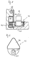
- the housing 43 differs from the housing 3 essentially only in that the cone-shaped end area with self-tapping thread of the bolt receiving bore 13 ' is on the top of the housing 43 and in the bottom a flat blind hole 44 opens, the diameter of which Diameter of the cylindrical extension of the housing 42 corresponds.
- the cylindrical extension of the housing 42 is also correspondingly shorter executed.
- the cylindrical Extension 7 of the housing 1 according to the embodiment 1 to 7 so short that the cup-shaped Housing 1 unchanged also for assembly and connection with the pot-shaped housing 43 can be used.
- the cup-shaped housing is included a flange-like overlapping the flat blind hole Edge.
- This flange-like edge 46 is in the pot-shaped Housing 3 is approximately triangular.
- the triangular one Flange 46 carries an additional in the area of its tip anchoring dowel-shaped extension 47.
Landscapes
- Engineering & Computer Science (AREA)
- General Engineering & Computer Science (AREA)
- Mechanical Engineering (AREA)
- Furniture Connections (AREA)
- Connection Of Plates (AREA)
- Cable Accessories (AREA)
- Hinges (AREA)
- Mechanical Coupling Of Light Guides (AREA)
- Joining Of Building Structures In Genera (AREA)
Abstract
Description
Die Erfindung betrifft einen Verbindungsbeschlag zum lösbaren Verbinden von Möbelteilen.The invention relates to a connection fitting for detachable Joining furniture parts.
Verbindungsbeschläge zum lösbaren Verbinden von Möbelteilen sind in unterschiedlichen Ausführungsformen bekannt. Derartige Verbindungsbeschläge weisen meist einen komplizierten Aufbau auf. Darüber hinaus lassen sie sich grundsätzlich nur mit Hilfe von besonderen Werkzeugen montieren.Connection fittings for releasably connecting furniture parts are known in different embodiments. Such connection fittings usually have a complicated structure. About that In addition, you can only use special ones Assemble tools.
Aufgabe der Erfindung ist es daher, einen Verbindungsbeschlag zu schaffen, der einen einfachen Aufbau besitzt und sich in einfacher Weise ohne besondere Werkzeuge im wesentlichen spielfrei nur von Hand montieren läßt.The object of the invention is therefore to provide a connection fitting create that has a simple structure and is in simple Way without special tools essentially free of play can only be assembled by hand.
Erfindungsgemäß wird diese Aufgabe durch einen Verbindungsbeschlag zum lösbaren Verbinden von Möbelteilen gelöst, der aus zwei in Aussparungen zweier Möbelteile einsetzbaren und in diesen befestigbaren, topfförmigen Gehäusen, die in ihren einander zugewandten Wandungen mit in ihrer Montagestellung fluchtenden Bohrungen versehen sind, und aus einem in der Bohrung des einen topfförmigen Gehäuses gehalterten und mit einem radialen Betätigungshebel versehenen Bolzen besteht, dessen vorderer, die Bohrung überragender, zapfenförmiger Endbereich in die Bohrung des anderen topfförmigen Gehäuses einführbar und derart mit schneidenden Gewindestegen versehen ist, daß der zapfenförmige Endbereich durch etwa eine Vierteldrehung in der Bohrung des anderen topfförmigen Gehäuses verriegelbar ist.According to the invention, this object is achieved by a connecting fitting for detachable connection of furniture parts, the out two usable in recesses of two pieces of furniture and in these attachable, pot-shaped housings that fit into each other facing walls with aligned in their mounting position Bores are provided, and one in the bore of one Pot-shaped housing and with a radial actuating lever provided bolt, the front, the bore outstanding, peg-shaped end area in the bore of the other cup-shaped housing insertable and such with cutting Threaded webs are provided that the peg-shaped end region by about a quarter turn in the other's hole Pot-shaped housing is lockable.
Der erfindungsgemäße Verbindungsbeschlag zeichnet sich durch einen besonders einfachen Aufbau aus. Er besitzt nur ein einziges bewegliches Teil, nämlich den in einem topfförmigen Gehäuse des Verbindungsbeschlags drehbar gelagerten Bolzen, der verriegelnd mit seinem vorderen Endbereich in die Bohrung des anderen topfförmigen Gehäuses eingreift. Der erfindungsgemäße Verbindungsbeschlag läßt sich ohne ein zusätzliches Werkzeug nur von Hand montieren, da zur Verriegelung der beiden Möbelteile nach dem Einführen des mit schneidenden Gewindestegen versehenen zapfenförmigen Endbereichs des Bolzens in die Bohrung des anderen Gehäuses nur der den Bolzen verdrehende Hebel von Hand umgelegt werden muß. Bei diesem Umlegen führt der Bolzen eine Drehung aus, die dazu führt, daß der mit schneidenden Gewindestegen versehene zapfenförmige Endbereich des Bolzens form- und kraftschlüssig an der Wandung der Bohrung des anderen Gehäuses angreift. Da die Verriegelung durch selbstschneidende Gewindestege erfolgt, werden die miteinander zu verbindenden Möbelteile durch die Drehung des Bolzens in die Verriegelungsstellung auch spannend gegeneinander gezogen, so daß ein etwa vorhandenes Spiel zwischen den miteinander zu verbindenden Möbelteilen beseitigt werden kann.The connecting fitting according to the invention is characterized by a particularly simple structure. He only has one moving part, namely in a pot-shaped housing of the connection fitting pivoted bolt, the locking with its front end portion in the other's hole pot-shaped housing engages. The connecting fitting according to the invention can only be done without an additional tool Assemble by hand as to lock the two furniture parts the introduction of the cone-shaped provided with cutting thread webs End portion of the bolt in the other's hole Only the lever rotating the bolt is turned by hand must become. The bolt rotates during this flipping which leads to the fact that the provided with cutting thread webs pin-shaped end area of the bolt positive and non-positive attacks on the wall of the bore of the other housing. Because the locking by self-tapping thread bars done, the pieces of furniture to be joined together the rotation of the bolt in the locking position is also exciting pulled against each other, so that an existing game between the pieces of furniture to be joined together can be.
Nach einer bevorzugten Ausführungsform ist vorgesehen, daß die Bohrungen zylindrische Fortsätze der Gehäusewandungen durchsetzen, die von einander entgegengesetzten Seiten her in eine ihren Durchmessern angepaßte Durchgangsbohrung einer Wand einsetzbar sind, deren Länge etwa gleich oder größer ist als die Summe der Längen der Fortsätze. Diese Ausgestaltung ermöglicht es, einfach und schnell Borde, Böden oder der Unterteilung dienende Platten an einer Zwischenwandung zu befestigen. Um die plattenförmigen Möbelteile an einer Zwischenwand zu befestigen, werden diese an ihrem Randbereich mit den Aussparungen versehen, in die die topfförmigen Gehäuse eingesetzt werden. Zweckmäßigerweise sind die Fortsätze an schmalen, mit den Stirnkanten der Möbelbretter fluchtenden Stirnseiten der Gehäuse angeordnet. Diese Anordnung wird dadurch erreicht, daß die Aussparungen die Stirnkanten der Möbelbretter anschneiden, so daß die Stirnseiten der Gehäuse in diesen Anschnitten liegen.According to a preferred embodiment it is provided that the Drill holes through cylindrical extensions of the housing walls, the opposite sides into theirs Diameter-adapted through hole of a wall can be used are whose length is approximately equal to or greater than the sum of the Lengths of the extensions. This configuration makes it easy and quickly shelves, floors or subdivision plates to attach to an intermediate wall. To the plate-shaped To fix furniture parts on a partition, they are attached the edge area with the recesses into which the cup-shaped Housing are used. These are expediently Extensions on narrow, with the front edges of the furniture boards aligned end faces of the housing arranged. This arrangement is achieved in that the recesses the front edges of the Cut furniture boards so that the front of the housing in these gates.
Nach einer anderen bevorzugten Ausführungsform ist vorgesehen, daß die topfförmigen Gehäuse in Aussparungen zweier rechtwinkelig miteinander zu verbindender Möbelteile eingesetzt und unmittelbar miteinander verriegelbar sind. Diese Ausgestaltung ermöglicht den Anschluß von Böden oder Zwischenplatten an eine endseitige vertikale Möbelwand, beispielsweise eine Seitenwand eines Schrankes.According to another preferred embodiment, that the cup-shaped housing is rectangular in recesses two furniture parts to be connected and used immediately can be locked together. This configuration enables the connection of floors or intermediate plates to one end vertical furniture wall, for example a side wall of a Cupboard.
Zweckmäßigerweise ist nur das den Bolzen halternde Gehäuse mit einem zylindrischen Fortsatz und das andere Gehäuse mit einer komplementären, den zylindrischen Fortsatz aufnehmenden Sacklochbohrung versehen, in deren Grund die Bohrung mündet.Expediently only the housing holding the bolt is included a cylindrical extension and the other housing with a complementary blind hole receiving the cylindrical extension provided, in the bottom of which the hole opens.
In weiterer Ausgestaltung der Erfindung ist vorgesehen, daß der mit einem selbstschneidenden Gewinde versehene zapfenförmige Endbereich des Bolzens auf gegenüberliegenden Seiten abgeflacht und die Bohrung des anderen Gehäuses ein dem Zapfenhüllprofil im wesentlichen angepaßtes rechteckiges Profil aufweist. Da der mit einem selbstschneidenden Gewinde versehene zapfenförmige Endbereich auf gegenüberliegenden Seiten bis etwa zu dem Bereich seines Kernschaftes abgeflacht ist, läßt sich dieser Endbereich frei in die entsprechend profilierte Bohrung des anderen Gehäuses bis zum Anschlag einschieben. Durch Umlegen des Betätigungshebels wird dann der Bolzen etwa um eine Vierteldrehung gedreht, so daß sich die stehengebliebenen Teile der Gewindegänge in die Wandung der Bohrung des anderen Teils einschneiden und die zylindrischen Fortsätze in der beschriebenen Weise gegeneinander ziehen.In a further embodiment of the invention it is provided that the with a self-tapping thread conical end area of the bolt flattened on opposite sides and the bore of the other housing is essentially a cone profile has adapted rectangular profile. Since the with a self-tapping threaded pin-shaped end area on opposite sides to about the area of his Core end is flattened, this end area freely in the correspondingly profiled hole in the other housing Push in as far as it will go. By flipping the operating lever then the bolt is turned about a quarter turn, so that the remaining parts of the threads in the Cut the wall of the hole in the other part and cut the cylindrical Pull extensions against each other in the manner described.
Der radiale Hebel kann einstückig (materialhomogen) mit dem Bolzen ausgebildet sein. Der Bolzen mit Hebel und zapfenförmigem Endbereich mit selbstschneidendem Gewinde bestehen zweckmäßigerweise aus Metalldruckguß.The radial lever can be made in one piece (homogeneous material) with the bolt be trained. The bolt with lever and peg-shaped End area with self-tapping thread expediently exist made of die-cast metal.
Der radiale Hebel kann abgekröpft sein.The radial lever can be bent.
Zweckmäßigerweise ist das den Bolzen halternde Gehäuse in seinem mittleren Bereich mit einer die Bohrung durchsetzenden, nach außen hin offenen Aussparung versehen, in der der radiale Hebel angeordnet ist. Die Breite dieser Aussparung bestimmt den Winkel, über den sich der Hebel zwischen seiner Montagestellung und seiner verriegelten Stellung verschwenken läßt. Die Aussparung ist zweckmäßigerweise in der Mitte des Gehäuses angebracht, so daß sie die in den diese begrenzenden, gegenüberliegenden Wänden des Gehäuses befindlichen Bohrungen unterbricht.The housing holding the bolt is expediently in its middle area with a penetrating hole Open recess on the outside, in which the radial lever is arranged. The width of this recess determines the angle over which the lever between its assembly position and can pivot its locked position. The recess is conveniently attached in the middle of the housing, so that they are in the walls that delimit them, opposite holes in the housing interrupts.
Nach einer bevorzugten Ausführungsform ist vorgesehen, daß beide Bohrungsabschnitte mit Gewindegängen für Gewindestege des Bolzens versehen sind. Diese Ausgestaltung führt dazu, daß der Bolzen bei der Drehung aus der Montagestellung in seine verriegelte Stellung eine die miteinander zu verbindenden Teile verspannende Einzugsbewegung in das Gehäuse ausführt, so daß auch ein eventuell vorhandenes größeres Spiel ausgeglichen werden kann.According to a preferred embodiment it is provided that both Bore sections with threads for thread webs of the bolt are provided. This configuration leads to the bolt when rotating from the assembly position to its locked Position a bracing the parts to be connected Feed movement in the housing, so that a possibly existing larger game can be compensated.
Zweckmäßigerweise besteht die Bohrung der hinteren Wandung des den Bolzen halternden Gehäuses aus einer Sacklochbohrung. Advantageously, there is a hole in the rear wall of the the bolt-holding housing from a blind hole.
In weiterer Ausgestaltung der Erfindung ist vorgesehen, daß das den Bolzen halternde Gehäuse aus zwei Gehäusehälften besteht, deren Trennebene durch die Achse der Bohrung verläuft. Die Gehäusehälften können an ihren Trennflächen mit Zapfen und zu diesen komplementären Bohrungen versehen sein, so daß sie sich durch einfaches Zusammenstecken zu dem Gehäuse montieren lassen. Diese Ausgestaltung des Gehäuses ermöglicht eine einfache Halterung und Lagerung des Bolzens durch Einlegen in die Gehäusehälften vor deren Zusammenfügen. Das Gehäuse bzw. die Gehäusehälften bestehen zweckmäßigerweise aus Kunststoff-Spritzgußteilen.In a further embodiment of the invention it is provided that the bolt-holding housing consists of two housing halves, whose parting plane runs through the axis of the bore. The housing halves can at their partitions with pegs and to these complementary holes are provided so that they are through just plug it into the housing. This Design of the housing enables easy mounting and storage of the bolt by inserting it into the housing halves before putting them together. The housing or the housing halves are made expediently made of plastic injection molded parts.
Der Betätigungshebel kann in seiner Verriegelungsstellung in eine Aussparung des Gehäuses einschwenkbar sein, so daß die Oberseite des Gehäuses und der in die Aussparung greifende Betätigungshebel im wesentlichen bündig sind. Zusätzlich können Einrichtungen zur Arretierung des Betätigungshebels in seiner Verriegelungsstellung vorgesehen sein.The operating lever can be in its locked position a recess of the housing can be swiveled so that the top of the housing and the operating lever reaching into the recess are essentially flush. In addition, facilities to lock the operating lever in its locking position be provided.
Ausführungsbeispiele der Erfindung werden nachstehend anhand der Zeichnung näher erläutert. In dieser zeigt
- Fig. 1
- eine Draufsicht auf eine erste Ausführungsform des erfindungsgemäßen Verbindungsbeschlages zum Anschluß zweier plattenförmiger Möbelteile an eine mit einer Durchgangsbohrung versehenen Zwischenwand im zusammengeschobenen, aber noch nicht verriegelten Zustand, teilweise im Schnitt,
- Fig. 2
- eine der Fig. 1 entsprechende Darstellung des Beschlages im verriegelten Zustand,
- Fig. 3
- eine Ansicht auf die Trennebenen der beiden zu einem topfförmigen Gehäuse zusammenfügbaren Gehäuseteile,
- Fig. 4
- eine Vorderansicht des den zapfenförmigen Endbereich des Bolzens aufnehmenden topfförmigen Gehäuses,
- Fig. 5
- eine Vorderansicht der beiden Gehäuseteile nach Fig. 3 in ihrer zum Zwecke des Zusammenfügens ausgerichteten Stellung,
- Fig. 6
- eine Draufsicht auf den Bolzen mit zapfenförmigem Endbereich und Betätigungshebel,
- Fig. 7
- eine Vorderansicht des Bolzens nach Fig. 6,
- Fig. 8
- einen Schnitt durch eine zweite Ausführungsform des erfindungsgemäßen Verbindungsbeschlages zum Verbinden zweier rechtwinkelig zueinander stehender Möbelteile und
- Fig. 9
- eine Draufsicht auf das den verriegelnden Zapfen aufnehmende topfförmige Gehäuse in Richtung des Pfeils A in Fig. 8.
- Fig. 1
- 2 shows a top view of a first embodiment of the connecting fitting according to the invention for connecting two plate-shaped furniture parts to an intermediate wall provided with a through hole in the pushed together but not yet locked state, partly in section,
- Fig. 2
- 1 corresponding representation of the fitting in the locked state,
- Fig. 3
- 2 shows a view of the parting planes of the two housing parts which can be joined together to form a cup-shaped housing,
- Fig. 4
- 2 shows a front view of the cup-shaped housing which receives the peg-shaped end region of the bolt,
- Fig. 5
- 3 in its position aligned for the purpose of joining,
- Fig. 6
- a plan view of the bolt with a peg-shaped end region and actuating lever,
- Fig. 7
- 6 shows a front view of the bolt according to FIG. 6,
- Fig. 8
- a section through a second embodiment of the connecting fitting according to the invention for connecting two furniture parts at right angles to each other and
- Fig. 9
- 8 shows a plan view of the pot-shaped housing receiving the locking pin in the direction of arrow A in FIG. 8.
Die aus den Fig. 1 bis 7 ersichtliche erste Ausführungsform des
erfindungsgemäßen Verbindungsbeschlages besteht aus einem ersten
topfförmigen Gehäuse 1, das in eine flache Sacklochbohrung eines
ersten plattenförmigen Möbelteils 2 eingelassen und in dieser
verankert ist, und aus einem zweiten topfförmigen Gehäuseteil 3,
das in entsprechender Weise in einer flachen Sacklochbohrung
eines zweiten plattenförmigen Möbelteils 4 eingelassen ist. Die
flachen Sacklochbohrungen beider Möbelteile 2, 4 schneiden deren
vorderen schmalen Stirnseiten an, so daß öffnungsspalte entstehen,
die durch die abgeflachten Vorderseiten 5, 6 der topfförmigen
Gehäuse 1, 3 geschlossen sind. Diese abgeflachten Vorderseiten
5, 6 der Gehäuse sind mit senkrecht auf diesen stehenden zapfenförmigen
zylindrischen Fortsätzen 7, 8 versehen, deren Durchmesser
dem Durchmesser einer Durchgangsbohrung 9 einer Gehäusewand
10 entspricht. Die zylindrischen Fortsätze 7, 8 sind mit
axial verlaufenden Bohrungen 12, 13 versehen. In der Bohrung 12
ist ein Bolzen 14 gehaltert, der mit einem vorderen mit einem
schneidenden Gewinde versehenen zapfenförmigen Endbereich 15 und
einem radialen Betätigungshebel 16 versehen ist. Der in der aus
Fig. 7 ersichtlichen Weise auf gegenüberliegenden Seiten abgeflachte
zapfenförmige Endbereich 15 des Bolzens 14 ist in der
aus Fig. 1 ersichtlichen Weise in die Bohrung 13 des zweiten
topfförmigen Gehäuses mit einem der Hüllkontur des zapfenförmigen
Endbereichs entsprechenden Bohrungsprofil einschiebbar. Nachdem
die aus Fig. 1 ersichtliche Vormontage durch Zusammenfügen
der beiden topfförmigen Gehäuseteile des Verbindungsbeschlages,
deren zylindrische Fortsätze 7, 8 in die Durchgangsbohrung 9 der
Zwischenwand 10 greifen, erfolgt ist, werden die topfförmigen
Gehäuse miteinander und an der Gehäusewand 10 dadurch verriegelt,
daß der radiale Betätigungshebel 16 aus seiner aus Fig. 1
ersichtlichen aufrechtstehenden Stellung um 90° in seine aus
Fig. 2 ersichtliche Verriegelungsstellung geschwenkt wird, in
der er in eine Aussparung auf der Oberseite des topfförmigen Gehäuses
1 greift. Bei dieser Drehung des Bolzens 14 um 90° schneiden
die nach der Abflachung des zapfenförmigen Endbereichs stehengebliebenen
selbstschneidenen Gewindegänge 18 in die zueinander
parallelen Wandungen 19 der Bohrung 13 ein, so daß die Verriegelung
bewirkt wird. The apparent from Figs. 1 to 7 first embodiment of the
Connection fitting according to the invention consists of a first
Pot-shaped housing 1, which in a flat blind hole
first panel-shaped furniture part 2 embedded and in this
is anchored, and from a second cup-shaped
Das Gehäuse 1 ist in der aus den Fig. 3 und 5 ersichtlichen Weise
aus zwei Gehäusehälften 20, 21 zusammengesetzt. Das Gehäuse 1
weist eine mittlere, nach oben hin offene und nach unten hin
durch einen Boden 22 begrenzte im wesentlichen rechteckige Aussparung
23 auf, die zwischen der vorderen Wand 5 und einer hinteren
Wand gebildet ist. Die vordere Wand 5 ist in der bereits beschriebenen
Form in ihrem mittleren Bereich mit einem zapfenförmigen
zylindrischen Fortsatz 7 versehen. Das Gehäuse 1 ist in
seiner Mittelebene 24 mit einer Bohrung versehen, die aus einem
vorderen Bohrungsabschnitt 25 und einem hinteren durch eine Wand
geschlossenen Bohrungsabschnitt 26 besteht. In die Bohrungsabschnitte
25 und 26 im vorderen und hinteren Teil des Gehäuses 1
sind jeweils in der aus Fig. 3 ersichtlichen Weise zwei Gewindegänge
27, 28 eingearbeitet. Das Gehäuse 1 weist an den in der
Mittelebene 24 liegenden Trennebenen Zapfen 29 und entsprechend
komplementäre Bohrungen 30 auf, so daß die aus Fig. 3 ersichtlichen
Gehäusehälften einfach zu dem aus den Fig. 1 und 2 ersichtlichen
Gehäuse 1 zusammengefügt werden können.The housing 1 is in the manner shown in FIGS. 3 and 5
composed of two
Der in dem Gehäuse 1 gehalterte Schaftteil des Bolzens 14 ist
mit zwei jeweils etwa nur einmal über den Bolzenumfang verlaufenden
Gewindestegen 33, 34 versehen, die im zusammengefügten Zustand
des Gehäuses 1 in die Gewindegänge 27, 28 greifen.The shaft part of the
Die Aussparung 23 des Gehäuses 1, in der der Betätigungshebel 16
liegt, ist durch seitliche Wandungen begrenzt.The
Die topfförmigen Gehäuse 1, 3 sind in der aus den Fig. 4 und 5
ersichtlichen Weise an ihren äußeren zylindrischen Wandungen mit
der Halterung dienenden ringförmig umlaufenden Rippen mit Sägezahnprofil
versehen.The cup-shaped
In dem Gehäuse 1 ist in der aus den Fig. 1 und 2 ersichtlichen
Weise der Bolzen 14 gelagert. Der Bolzen 14 besteht aus einem
Schaftteil 32 mit den etwa nur einmal über dessen Umfang verlaufenden
Gewindestegen 33, 34 und dem diesen nach vorne hin verlängernden
zapfenförmigen Endbereich 15 mit auf gegenüberliegenden
Seiten abgeflachten selbstschneidenden Gewinde 18. Zwischen den
Gewindestegen 33, 34 ist mit dem Schaftteil 32 einstückig der
abgekröpfte Betätigungshebel 16 verbunden.In the housing 1 can be seen in FIGS. 1 and 2
Way of the
Wird nach dem Zusammenschieben der die Möbelplatten 2, 4 tragenden
topfförmigen Gehäuse in die aus Fig. 1 ersichtliche vormontierte
Stellung der Betätigungshebel 16 um 90° in die aus Fig. 2
ersichtliche Stellung umgelegt, schneiden die Gewindegänge 18
verriegelnd in die Wandungsteile 19 der Bohrung 13 des topfförmigen
Gehäuses 3 ein. Durch dieses Einschneiden werden die zylindrischen
Fortsätze 7, 8 in der Durchgangsbohrung 9 aufeinander
zubewegt. Dieser Bewegung wird die Einzugsbewegung des Schaftteils
9 überlagert, die sich aus dem Einschrauben der in die Gewindegänge
27, 28 greifenden Gewindestege 33, 34 ergibt. Durch
dieses Zusammenziehen verschwindet der in der vormontierten, aus
Fig. 1 ersichtlichen Stellung noch vorhandene Spalt a zwischen
dem plattenförmigen Teil 4 und der Gehäusewand 10.Is after pushing together the furniture panels 2, 4 supporting
Pot-shaped housing in the preassembled from FIG. 1
Position of the actuating lever 16 by 90 ° in that from FIG. 2
visible position flipped, the
Der erfindungsgemäße Verbindungsbeschlag läßt sich in einfacher Weise wieder dadurch lösen, daß der Hebel aus seiner aus Fig. 2 ersichtlichen arretierten Stellung wieder in seine aus Fig. 1 ersichtliche entriegelte Stellung zurückgeschwenkt wird.The connection fitting according to the invention can be simplified Solve the way again by pulling the lever out of its from FIG apparent locked position back into its from Fig. 1st apparent unlocked position is pivoted back.
Das Ausführungsbeispiel nach den Fig. 8 und 9 unterscheidet sich
von dem nach den Fig. 1 bis 7 dadurch, daß die in den Endbereich
zweier rechtwinkelig miteinander zu verbindender Möbelplatten
40, 41 eingelassenen topfförmigen Gehäuse 42, 43 unmittelbar miteinander
verriegelt werden. Der aus den Fig. 8 und 9 ersichtliche
Verbindungsbeschlag eignet sich also beispielsweise dazu,
einen Boden oder eine Zwischenwand an einer endseitigen Wand
eines Möbels, beispielsweise einer Seitenwand eines Schrankes,
zu montieren.The embodiment of FIGS. 8 and 9 differs
of that according to FIGS. 1 to 7 in that the in the end region
two furniture panels to be connected at
Das den Bolzen lagernde Gehäuse 42 entspricht einschließlich des
Bolzens grundsätzlich dem Gehäuse 1 und dem Bolzen 14 nach den
Figuren 3 und 5 bis 7, so daß zur Darstellung des Gehäuses 42
und des in diesem gelagerten Bolzens auf die vorstehende Beschreibung
Bezug genommen wird.The bolt bearing housing 42 corresponds to the
Bolts basically the housing 1 and the
Das Gehäuse 43 unterscheidet sich von dem Gehäuse 3 im wesentlichen
nur dadurch, daß die im zapfenförmigen Endbereich mit
selbstschneidendem Gewinde des Bolzens aufnehmende Bohrung 13'
sich auf der Oberseite des Gehäuses 43 befindet und in den Grund
einer flachen Sacklochbohrung 44 mündet, deren Durchmesser dem
Durchmesser des zylindrischen Fortsatzes des Gehäuses 42 entspricht.The
Entsprechend der geringeren Tiefe der Sacklochbohrung 44 ist der
zylindrische Fortsatz des Gehäuses 42 ebenfalls entsprechend kürzer
ausgeführt. Es besteht jedoch auch die Möglichkeit, den zylindrischen
Fortsatz 7 des Gehäuses 1 nach dem Ausführungsbeispiel
der Fig. 1 bis 7 so kurz auszuführen, daß das topfförmige
Gehäuse 1 unverändert auch zur Montage und Verbindung mit dem
topfförmigen Gehäuse 43 verwendet werden kann.Corresponding to the smaller depth of the blind bore 44, the
cylindrical extension of the housing 42 is also correspondingly shorter
executed. However, there is also the option of the cylindrical
Extension 7 of the housing 1 according to the embodiment
1 to 7 so short that the cup-shaped
Housing 1 unchanged also for assembly and connection with the
pot-shaped
In allen Ausführungsbeispielen sind die topfförmigen Gehäuse mit
einem die flache Sacklochbohrung übergreifenden flanschartigen
Rand versehen. Dieser flanschartige Rand 46 ist bei dem topfförmigen
Gehäuse 3 etwa dreieckförmig ausgebildet. Der dreiecksförmige
Flansch 46 trägt im Bereich seiner Spitze einen zusätzlichen
der Verankerung dienenden dübelförmigen Fortsatz 47.In all of the exemplary embodiments, the cup-shaped housing is included
a flange-like overlapping the flat blind hole
Edge. This flange-
Claims (14)
- A connecting fitting for releasably connecting furniture parts, comprising
two pot-shaped housings (1, 3; 42, 43) to be inserted in recesses of two furniture parts (2, 3; 40, 41) and to be fixed in the same, which in their walls facing each other are provided with bores aligned in their mounting position, and
a bolt (14) held in the bore (25, 26) of the one pot-shaped housing (1, 42) and provided with a radial actuating lever (16), whose front pin-shaped end portion (15) protruding beyond the bore can be introduced into the bore (13) of the other pot-shaped housing (3, 43) and is provided with cutting thread webs (18) such that the pin-shaped end portion (15) can be locked in the bore (13) of the other pot-shaped housing (3, 43) by about a quarter turn. - The connecting fitting as claimed in claim 1, characterized in that the bores extend through cylindrical projections (7, 8) of the housing walls, which from opposite sides can be inserted in a diameter-adapted through hole (9) of a wall (10) whose length is approximately equal to or larger than the sum of the lengths of the cylindrical projections (7, 8).
- The connecting fitting as claimed in claim 1 or 2, characterized in that the cylindrical projections (7, 8) are disposed on narrow end faces (5, 6) of the housings (1, 3), which are aligned with the front edges of the furniture boards (2, 4).
- The connecting fitting as claimed in claim 1, characterized in that the pot-shaped housings (42, 43) can be inserted in recesses of two furniture parts (40, 41) to be connected with each other at right angles and can directly be locked with each other.
- The connecting fitting as claimed in claim 4, characterized in that only the housing (42) holding the bolt (14) is provided with a cylindrical projection and the other housing (43) is provided with a complementary blind hole (44) receiving the cylindrical projection, the bore (13') opening in the bottom of said blind hole.
- The connecting fitting as claimed in any of claims 1 to 5, characterized in that the pin-shaped end portion (15) of the bolt (14), which is provided with a self-cutting thread (18), is flattened on opposing sides, and the bore of the other housing (3, 43) has a rectangular profile substantially corresponding to the envelope profile of the pin.
- The connecting fitting as claimed in any of claims 1 to 6, characterized in that the radial lever (16) is formed integrally (of homogeneous material) with the bolt (14).
- The connecting fitting as claimed in any of claims 1 to 7, characterized in that the radial lever (16) is bent at right angle.
- The connecting fitting as claimed in any of claims 1 to 8, characterized in that in its middle portion the housing (1, 42) holding the bolt is provided with a recess (23) extending through the bore (25, 26) and open to the outside, in which recess the radial actuating lever (16) is disposed.
- The connecting fitting as claimed in any of claims 1 to 9, characterized in that the recess (23) interrupts the bore portions (25, 26) located in the opposing walls of the housing defining the same.
- The connecting fitting as claimed in any of claims 1 to 10, characterized in that the two bore portions (25, 26) are provided with thread courses (27, 28) for thread webs (33, 34) of the bolt (14).
- The connecting fitting as claimed in any of claims 1 to 11, characterized in that the bore of the rear wall of the housing (1, 42) is a blind hole (26).
- The connecting fitting as claimed in any of claims 1 to 12, characterized in that the housing (1, 42) consists of two housing halves (20, 21), whose parting plane (24) extends through the axis of the bolt (14).
- The connecting fitting as claimed in claim 13, characterized in that at their parting surfaces the housing halves (20, 21) are provided with pins (29) and complementary bores (30).
Applications Claiming Priority (2)
| Application Number | Priority Date | Filing Date | Title |
|---|---|---|---|
| DE29510504U | 1995-06-28 | ||
| DE29510504U DE29510504U1 (en) | 1995-06-28 | 1995-06-28 | Connecting fitting |
Publications (3)
| Publication Number | Publication Date |
|---|---|
| EP0751306A2 EP0751306A2 (en) | 1997-01-02 |
| EP0751306A3 EP0751306A3 (en) | 2001-01-03 |
| EP0751306B1 true EP0751306B1 (en) | 2002-11-27 |
Family
ID=8009881
Family Applications (1)
| Application Number | Title | Priority Date | Filing Date |
|---|---|---|---|
| EP96107429A Expired - Lifetime EP0751306B1 (en) | 1995-06-28 | 1996-05-10 | Connecting fitting |
Country Status (11)
| Country | Link |
|---|---|
| US (1) | US5762442A (en) |
| EP (1) | EP0751306B1 (en) |
| JP (1) | JP3150905B2 (en) |
| KR (1) | KR100221863B1 (en) |
| AT (1) | ATE228618T1 (en) |
| DE (2) | DE29510504U1 (en) |
| ES (1) | ES2187591T3 (en) |
| HU (1) | HU216516B (en) |
| PL (1) | PL315017A1 (en) |
| SI (1) | SI9600207A (en) |
| TW (1) | TW387037B (en) |
Families Citing this family (26)
| Publication number | Priority date | Publication date | Assignee | Title |
|---|---|---|---|---|
| DE29721068U1 (en) * | 1997-11-27 | 1998-01-22 | Arturo Salice S.P.A., Novedrate, Como | Connecting fitting |
| SE512907C2 (en) * | 1998-10-02 | 2000-06-05 | Kinnarps Ab | Linking device |
| AT407777B (en) * | 1999-04-26 | 2001-06-25 | Blum Gmbh Julius | CONNECTING FITTING FOR DETACHABLE CONNECTION OF TWO FURNITURE PARTS |
| DE20302694U1 (en) * | 2003-02-19 | 2003-06-12 | Häfele GmbH & Co., 72202 Nagold | fitting |
| ITMI20030799A1 (en) * | 2003-04-17 | 2004-10-18 | Mauri Flli Srl | DEVICE FOR THE JOINTING OF TWO PARTS BETWEEN THEM ARRANGED AT 90 °. |
| DE10333809B3 (en) * | 2003-07-24 | 2005-02-24 | Steelcase Werndl Aktiengesellschaft | locking device |
| WO2006042564A1 (en) | 2004-10-14 | 2006-04-27 | Steelcase Werndl Ag | Locking device |
| US20080084143A1 (en) * | 2006-10-06 | 2008-04-10 | Wen-Te Ho | Detachable fastener assembly |
| US7530651B2 (en) * | 2007-07-13 | 2009-05-12 | Grace Chance Enterprise Co., Ltd | RTA modular desktop cabinet |
| US7390069B1 (en) * | 2007-07-13 | 2008-06-24 | Grace Chance Enterprise Co., Ltd. | Ready-to-assemble modular desk |
| GB2457480B (en) * | 2008-02-14 | 2010-09-29 | Kenmark Ind Co Ltd | Latch module |
| US20090206613A1 (en) * | 2008-02-15 | 2009-08-20 | Kenmark Industrial Co., Ltd. | Latch module |
| US20100202852A1 (en) * | 2009-02-09 | 2010-08-12 | Krause Steven T | No-tools panel coupler and insert |
| US20100283363A1 (en) * | 2009-05-05 | 2010-11-11 | Bell'o International Corp. | Ready to assemble modular furniture |
| US11744364B2 (en) | 2017-02-23 | 2023-09-05 | Mcs Industries, Inc. | Wall hanging system and related methods |
| WO2018156836A1 (en) | 2017-02-23 | 2018-08-30 | Mcs Industries, Inc. | System and method for hanging an article from a support surface |
| USD911813S1 (en) * | 2018-02-23 | 2021-03-02 | Mcs Industries, Inc. | Cam lock |
| PL239329B1 (en) * | 2018-04-09 | 2021-11-22 | Marcin Podskarbi | Eccentric joint, preferably for furniture |
| PL239332B1 (en) * | 2018-04-09 | 2021-11-22 | Marcin Podskarbi | Expanding double joint, preferably for furniture |
| PL239331B1 (en) * | 2018-04-09 | 2021-11-22 | Marcin Podskarbi | Plugged double joint, preferably for furniture |
| PL239334B1 (en) * | 2018-04-09 | 2021-11-22 | Marcin Podskarbi | Compression double joint, preferably for furniture |
| PL239330B1 (en) * | 2018-04-09 | 2021-11-22 | Marcin Podskarbi | Plugged single joint, preferably for furniture |
| PL239327B1 (en) * | 2018-04-09 | 2021-11-22 | Marcin Podskarbi | Expanding-keyed joint, preferably for furniture |
| PL239328B1 (en) * | 2018-04-09 | 2021-11-22 | Marcin Podskarbi | Keeper joint, preferably for furniture |
| PL239333B1 (en) * | 2018-04-09 | 2021-11-22 | Marcin Podskarbi | Expanding single joint, preferably for furniture |
| USD972401S1 (en) | 2020-05-04 | 2022-12-13 | Mcs Industries, Inc. | Cam lock fastener |
Family Cites Families (8)
| Publication number | Priority date | Publication date | Assignee | Title |
|---|---|---|---|---|
| FR2445461A3 (en) * | 1978-12-26 | 1980-07-25 | Spinelli Giuseppe | Demountable joint for furniture panels - uses cased hammer head swivel pin with bent radial hand lever and engaging keyhole counterpart |
| DE2919769A1 (en) * | 1979-05-16 | 1980-11-27 | Anton Hopf Plastik Spritzgussh | Wedge type furniture joining fitting - comprises wedge-shaped pin passing through- and locked in plate housing |
| DE3047642A1 (en) * | 1980-12-17 | 1982-10-28 | Arturo Salice S.p.A., 22060 Novedrate, Como | CONNECTING FITTING |
| EP0431786A1 (en) * | 1989-12-04 | 1991-06-12 | Camloc (U.K.) Limited | Quick release structural fastener |
| US4984926A (en) * | 1989-12-07 | 1991-01-15 | Titus Tool Company Limited | Connector for securing furniture panels at right angles to one another |
| DE9302527U1 (en) * | 1993-02-22 | 1993-04-08 | REME Möbelbeschläge GmbH, 4794 Hövelhof | Fitting for connecting panel-shaped furniture or interior fittings |
| GB2285106B (en) * | 1993-12-23 | 1997-07-16 | Titus Int Ltd | Joint forming device |
| DE29504622U1 (en) * | 1995-03-17 | 1995-05-11 | Arturo Salice S.P.A., Novedrate, Como | Connecting fitting |
-
1995
- 1995-06-28 DE DE29510504U patent/DE29510504U1/en not_active Expired - Lifetime
-
1996
- 1996-05-10 ES ES96107429T patent/ES2187591T3/en not_active Expired - Lifetime
- 1996-05-10 AT AT96107429T patent/ATE228618T1/en not_active IP Right Cessation
- 1996-05-10 EP EP96107429A patent/EP0751306B1/en not_active Expired - Lifetime
- 1996-05-10 DE DE59609900T patent/DE59609900D1/en not_active Expired - Fee Related
- 1996-05-22 TW TW085106031A patent/TW387037B/en not_active IP Right Cessation
- 1996-06-26 HU HU9601764A patent/HU216516B/en not_active IP Right Cessation
- 1996-06-27 US US08/670,550 patent/US5762442A/en not_active Expired - Fee Related
- 1996-06-27 KR KR1019960024609A patent/KR100221863B1/en not_active IP Right Cessation
- 1996-06-28 JP JP16915896A patent/JP3150905B2/en not_active Expired - Fee Related
- 1996-06-28 SI SI9600207A patent/SI9600207A/en unknown
- 1996-06-28 PL PL96315017A patent/PL315017A1/en unknown
Also Published As
| Publication number | Publication date |
|---|---|
| KR970002010A (en) | 1997-01-24 |
| US5762442A (en) | 1998-06-09 |
| TW387037B (en) | 2000-04-11 |
| ATE228618T1 (en) | 2002-12-15 |
| ES2187591T3 (en) | 2003-06-16 |
| DE29510504U1 (en) | 1995-09-07 |
| HU216516B (en) | 1999-07-28 |
| HUP9601764A1 (en) | 1997-02-28 |
| SI9600207A (en) | 1997-02-28 |
| EP0751306A2 (en) | 1997-01-02 |
| HU9601764D0 (en) | 1996-08-28 |
| DE59609900D1 (en) | 2003-01-09 |
| EP0751306A3 (en) | 2001-01-03 |
| PL315017A1 (en) | 1997-01-06 |
| KR100221863B1 (en) | 1999-09-15 |
| JPH09158920A (en) | 1997-06-17 |
| JP3150905B2 (en) | 2001-03-26 |
Similar Documents
| Publication | Publication Date | Title |
|---|---|---|
| EP0751306B1 (en) | Connecting fitting | |
| EP0761130B1 (en) | Mounting fitting for drawer front panels | |
| DE69518197T2 (en) | Fastening element for fittings, as well as hinge equipped with such elements | |
| DE69303401T2 (en) | Fastening, for example for furniture parts and the like | |
| EP0708256B1 (en) | Connecting fitting | |
| DE3127795C2 (en) | Connecting fitting | |
| DE2610200A1 (en) | Connector for furniture panels - comprises cam in one panel engaging headed pin in other panel | |
| AT390480B (en) | FITTING FOR SOLVABLY CONNECTING TWO PLATE-SHAPED FURNITURE PIECES IN THE RIGHT ANGLE | |
| DE2546749A1 (en) | Detachable connector for furniture panels - has recessed holder with holding bolt or peg for panels at right angles | |
| CH696150A5 (en) | Mounting bracket with bayonet coupling. | |
| DE2724201A1 (en) | FURNITURE CONSTRUCTION SYSTEM OR ASSEMBLY | |
| DE69016621T2 (en) | Connecting fitting. | |
| DE2059870A1 (en) | Dismountable furniture, e.g. Shelf, box, cupboard or the like. | |
| DE3928486A1 (en) | Constructional section for frames or supports - consists of two sections joined at ends by connection | |
| DE2112164C3 (en) | Device for the detachable connection of two parts | |
| DE3835835A1 (en) | WINDOW, DOOR OD. THE LIKE, AT THE BZW. THAT IS AT LEAST OF THE Sash Frame Made From Metal Or Plastic Profiles | |
| DE4327628C2 (en) | Fastener | |
| EP0267200A1 (en) | Fitting for releasable connection of two components. | |
| DE1298373B (en) | Furniture fittings | |
| DE20002307U1 (en) | Connecting fitting | |
| DE8336732U1 (en) | Connection element for modular furniture | |
| DE2643354A1 (en) | Two piece connector for furniture panels - has rotatable fitting with bayonet slot engaging bolt head protruding from opposite part | |
| DE2343933A1 (en) | Window actuator housing and bearing rosette - spacing sleeve with adjusting slots | |
| EP2020513B1 (en) | Fitting for connecting two furniture boards | |
| DE202005016961U1 (en) | Kit for building frames comprises bars and connector plates which have keyhole-shaped slots, into which bolts on bars with undercut sections fit |
Legal Events
| Date | Code | Title | Description |
|---|---|---|---|
| PUAI | Public reference made under article 153(3) epc to a published international application that has entered the european phase |
Free format text: ORIGINAL CODE: 0009012 |
|
| AK | Designated contracting states |
Kind code of ref document: A2 Designated state(s): AT DE ES FR GB IT |
|
| 17P | Request for examination filed |
Effective date: 20000814 |
|
| PUAL | Search report despatched |
Free format text: ORIGINAL CODE: 0009013 |
|
| AK | Designated contracting states |
Kind code of ref document: A3 Designated state(s): AT DE ES FR GB IT |
|
| RIC1 | Information provided on ipc code assigned before grant |
Free format text: 7F 16B 12/16 A, 7A 47B 95/00 B, 7F 16B 12/20 B |
|
| GRAG | Despatch of communication of intention to grant |
Free format text: ORIGINAL CODE: EPIDOS AGRA |
|
| 17Q | First examination report despatched |
Effective date: 20020411 |
|
| GRAG | Despatch of communication of intention to grant |
Free format text: ORIGINAL CODE: EPIDOS AGRA |
|
| GRAH | Despatch of communication of intention to grant a patent |
Free format text: ORIGINAL CODE: EPIDOS IGRA |
|
| GRAH | Despatch of communication of intention to grant a patent |
Free format text: ORIGINAL CODE: EPIDOS IGRA |
|
| GRAA | (expected) grant |
Free format text: ORIGINAL CODE: 0009210 |
|
| AK | Designated contracting states |
Kind code of ref document: B1 Designated state(s): AT DE ES FR GB IT |
|
| PG25 | Lapsed in a contracting state [announced via postgrant information from national office to epo] |
Ref country code: GB Free format text: LAPSE BECAUSE OF FAILURE TO SUBMIT A TRANSLATION OF THE DESCRIPTION OR TO PAY THE FEE WITHIN THE PRESCRIBED TIME-LIMIT Effective date: 20021127 Ref country code: FR Free format text: LAPSE BECAUSE OF FAILURE TO SUBMIT A TRANSLATION OF THE DESCRIPTION OR TO PAY THE FEE WITHIN THE PRESCRIBED TIME-LIMIT Effective date: 20021127 |
|
| REF | Corresponds to: |
Ref document number: 228618 Country of ref document: AT Date of ref document: 20021215 Kind code of ref document: T |
|
| REG | Reference to a national code |
Ref country code: GB Ref legal event code: FG4D Free format text: NOT ENGLISH |
|
| REF | Corresponds to: |
Ref document number: 59609900 Country of ref document: DE Date of ref document: 20030109 |
|
| GBV | Gb: ep patent (uk) treated as always having been void in accordance with gb section 77(7)/1977 [no translation filed] |
Effective date: 20021127 |
|
| REG | Reference to a national code |
Ref country code: ES Ref legal event code: FG2A Ref document number: 2187591 Country of ref document: ES Kind code of ref document: T3 |
|
| EN | Fr: translation not filed | ||
| PLBE | No opposition filed within time limit |
Free format text: ORIGINAL CODE: 0009261 |
|
| STAA | Information on the status of an ep patent application or granted ep patent |
Free format text: STATUS: NO OPPOSITION FILED WITHIN TIME LIMIT |
|
| 26N | No opposition filed |
Effective date: 20030828 |
|
| PGFP | Annual fee paid to national office [announced via postgrant information from national office to epo] |
Ref country code: ES Payment date: 20050509 Year of fee payment: 10 |
|
| PGFP | Annual fee paid to national office [announced via postgrant information from national office to epo] |
Ref country code: AT Payment date: 20050519 Year of fee payment: 10 |
|
| PGFP | Annual fee paid to national office [announced via postgrant information from national office to epo] |
Ref country code: DE Payment date: 20050531 Year of fee payment: 10 |
|
| PG25 | Lapsed in a contracting state [announced via postgrant information from national office to epo] |
Ref country code: AT Free format text: LAPSE BECAUSE OF NON-PAYMENT OF DUE FEES Effective date: 20060510 |
|
| PG25 | Lapsed in a contracting state [announced via postgrant information from national office to epo] |
Ref country code: ES Free format text: LAPSE BECAUSE OF NON-PAYMENT OF DUE FEES Effective date: 20060511 |
|
| PGFP | Annual fee paid to national office [announced via postgrant information from national office to epo] |
Ref country code: IT Payment date: 20060531 Year of fee payment: 11 |
|
| PG25 | Lapsed in a contracting state [announced via postgrant information from national office to epo] |
Ref country code: DE Free format text: LAPSE BECAUSE OF NON-PAYMENT OF DUE FEES Effective date: 20061201 |
|
| REG | Reference to a national code |
Ref country code: ES Ref legal event code: FD2A Effective date: 20060511 |
|
| PG25 | Lapsed in a contracting state [announced via postgrant information from national office to epo] |
Ref country code: IT Free format text: LAPSE BECAUSE OF NON-PAYMENT OF DUE FEES Effective date: 20070510 |