EP0751237B1 - Substrat segmenté pour la déposition du diamant par le procédé arc-jet - Google Patents
Substrat segmenté pour la déposition du diamant par le procédé arc-jet Download PDFInfo
- Publication number
- EP0751237B1 EP0751237B1 EP96201500A EP96201500A EP0751237B1 EP 0751237 B1 EP0751237 B1 EP 0751237B1 EP 96201500 A EP96201500 A EP 96201500A EP 96201500 A EP96201500 A EP 96201500A EP 0751237 B1 EP0751237 B1 EP 0751237B1
- Authority
- EP
- European Patent Office
- Prior art keywords
- base plate
- mesa
- segments
- diamond
- mandrel
- Prior art date
- Legal status (The legal status is an assumption and is not a legal conclusion. Google has not performed a legal analysis and makes no representation as to the accuracy of the status listed.)
- Expired - Lifetime
Links
- 239000010432 diamond Substances 0.000 title claims description 63
- 229910003460 diamond Inorganic materials 0.000 title claims description 62
- 230000008021 deposition Effects 0.000 title claims description 38
- 239000000758 substrate Substances 0.000 title description 60
- 238000000151 deposition Methods 0.000 claims description 40
- ZOKXTWBITQBERF-UHFFFAOYSA-N Molybdenum Chemical compound [Mo] ZOKXTWBITQBERF-UHFFFAOYSA-N 0.000 claims description 22
- 229910052750 molybdenum Inorganic materials 0.000 claims description 22
- 239000011733 molybdenum Substances 0.000 claims description 22
- 238000000034 method Methods 0.000 claims description 19
- OKTJSMMVPCPJKN-UHFFFAOYSA-N Carbon Chemical compound [C] OKTJSMMVPCPJKN-UHFFFAOYSA-N 0.000 claims description 15
- 238000004519 manufacturing process Methods 0.000 claims description 7
- RYGMFSIKBFXOCR-UHFFFAOYSA-N Copper Chemical compound [Cu] RYGMFSIKBFXOCR-UHFFFAOYSA-N 0.000 claims description 6
- 229910002804 graphite Inorganic materials 0.000 claims description 6
- 239000010439 graphite Substances 0.000 claims description 6
- 229910001182 Mo alloy Inorganic materials 0.000 claims description 4
- 239000011888 foil Substances 0.000 claims description 4
- NRTOMJZYCJJWKI-UHFFFAOYSA-N Titanium nitride Chemical compound [Ti]#N NRTOMJZYCJJWKI-UHFFFAOYSA-N 0.000 claims description 3
- 239000004744 fabric Substances 0.000 claims description 2
- 239000011889 copper foil Substances 0.000 claims 1
- 239000010408 film Substances 0.000 description 29
- 239000010410 layer Substances 0.000 description 15
- 239000000463 material Substances 0.000 description 13
- 238000005336 cracking Methods 0.000 description 8
- 238000005229 chemical vapour deposition Methods 0.000 description 7
- 230000008901 benefit Effects 0.000 description 5
- 229910052802 copper Inorganic materials 0.000 description 5
- 239000010949 copper Substances 0.000 description 5
- 230000008569 process Effects 0.000 description 5
- ATJFFYVFTNAWJD-UHFFFAOYSA-N Tin Chemical compound [Sn] ATJFFYVFTNAWJD-UHFFFAOYSA-N 0.000 description 4
- 239000011229 interlayer Substances 0.000 description 4
- 230000001464 adherent effect Effects 0.000 description 3
- 238000000576 coating method Methods 0.000 description 3
- 238000001816 cooling Methods 0.000 description 3
- 238000005520 cutting process Methods 0.000 description 3
- 238000001540 jet deposition Methods 0.000 description 3
- RTAQQCXQSZGOHL-UHFFFAOYSA-N Titanium Chemical compound [Ti] RTAQQCXQSZGOHL-UHFFFAOYSA-N 0.000 description 2
- 238000005137 deposition process Methods 0.000 description 2
- 230000003993 interaction Effects 0.000 description 2
- 230000004048 modification Effects 0.000 description 2
- 238000012986 modification Methods 0.000 description 2
- 230000009467 reduction Effects 0.000 description 2
- 239000010409 thin film Substances 0.000 description 2
- 239000010936 titanium Substances 0.000 description 2
- 229910052719 titanium Inorganic materials 0.000 description 2
- WFKWXMTUELFFGS-UHFFFAOYSA-N tungsten Chemical compound [W] WFKWXMTUELFFGS-UHFFFAOYSA-N 0.000 description 2
- 229910052721 tungsten Inorganic materials 0.000 description 2
- 239000010937 tungsten Substances 0.000 description 2
- QCWXUUIWCKQGHC-UHFFFAOYSA-N Zirconium Chemical compound [Zr] QCWXUUIWCKQGHC-UHFFFAOYSA-N 0.000 description 1
- CPTCUNLUKFTXKF-UHFFFAOYSA-N [Ti].[Zr].[Mo] Chemical compound [Ti].[Zr].[Mo] CPTCUNLUKFTXKF-UHFFFAOYSA-N 0.000 description 1
- 230000005540 biological transmission Effects 0.000 description 1
- 229910052799 carbon Inorganic materials 0.000 description 1
- 239000011248 coating agent Substances 0.000 description 1
- 238000011109 contamination Methods 0.000 description 1
- -1 e.g. Substances 0.000 description 1
- 238000010292 electrical insulation Methods 0.000 description 1
- 238000000605 extraction Methods 0.000 description 1
- 239000012530 fluid Substances 0.000 description 1
- 239000012212 insulator Substances 0.000 description 1
- 238000003754 machining Methods 0.000 description 1
- 230000003287 optical effect Effects 0.000 description 1
- 230000002028 premature Effects 0.000 description 1
- 238000002360 preparation method Methods 0.000 description 1
- 239000011253 protective coating Substances 0.000 description 1
- 238000005086 pumping Methods 0.000 description 1
- 239000011819 refractory material Substances 0.000 description 1
- 238000000926 separation method Methods 0.000 description 1
- 230000035882 stress Effects 0.000 description 1
- 239000000126 substance Substances 0.000 description 1
- 230000002194 synthesizing effect Effects 0.000 description 1
- 230000008646 thermal stress Effects 0.000 description 1
- 229910000663 tzm Inorganic materials 0.000 description 1
- 229910052726 zirconium Inorganic materials 0.000 description 1
Images
Classifications
-
- C—CHEMISTRY; METALLURGY
- C23—COATING METALLIC MATERIAL; COATING MATERIAL WITH METALLIC MATERIAL; CHEMICAL SURFACE TREATMENT; DIFFUSION TREATMENT OF METALLIC MATERIAL; COATING BY VACUUM EVAPORATION, BY SPUTTERING, BY ION IMPLANTATION OR BY CHEMICAL VAPOUR DEPOSITION, IN GENERAL; INHIBITING CORROSION OF METALLIC MATERIAL OR INCRUSTATION IN GENERAL
- C23C—COATING METALLIC MATERIAL; COATING MATERIAL WITH METALLIC MATERIAL; SURFACE TREATMENT OF METALLIC MATERIAL BY DIFFUSION INTO THE SURFACE, BY CHEMICAL CONVERSION OR SUBSTITUTION; COATING BY VACUUM EVAPORATION, BY SPUTTERING, BY ION IMPLANTATION OR BY CHEMICAL VAPOUR DEPOSITION, IN GENERAL
- C23C16/00—Chemical coating by decomposition of gaseous compounds, without leaving reaction products of surface material in the coating, i.e. chemical vapour deposition [CVD] processes
- C23C16/22—Chemical coating by decomposition of gaseous compounds, without leaving reaction products of surface material in the coating, i.e. chemical vapour deposition [CVD] processes characterised by the deposition of inorganic material, other than metallic material
- C23C16/26—Deposition of carbon only
- C23C16/27—Diamond only
- C23C16/276—Diamond only using plasma jets
-
- C—CHEMISTRY; METALLURGY
- C23—COATING METALLIC MATERIAL; COATING MATERIAL WITH METALLIC MATERIAL; CHEMICAL SURFACE TREATMENT; DIFFUSION TREATMENT OF METALLIC MATERIAL; COATING BY VACUUM EVAPORATION, BY SPUTTERING, BY ION IMPLANTATION OR BY CHEMICAL VAPOUR DEPOSITION, IN GENERAL; INHIBITING CORROSION OF METALLIC MATERIAL OR INCRUSTATION IN GENERAL
- C23C—COATING METALLIC MATERIAL; COATING MATERIAL WITH METALLIC MATERIAL; SURFACE TREATMENT OF METALLIC MATERIAL BY DIFFUSION INTO THE SURFACE, BY CHEMICAL CONVERSION OR SUBSTITUTION; COATING BY VACUUM EVAPORATION, BY SPUTTERING, BY ION IMPLANTATION OR BY CHEMICAL VAPOUR DEPOSITION, IN GENERAL
- C23C16/00—Chemical coating by decomposition of gaseous compounds, without leaving reaction products of surface material in the coating, i.e. chemical vapour deposition [CVD] processes
- C23C16/01—Chemical coating by decomposition of gaseous compounds, without leaving reaction products of surface material in the coating, i.e. chemical vapour deposition [CVD] processes on temporary substrates, e.g. substrates subsequently removed by etching
-
- C—CHEMISTRY; METALLURGY
- C23—COATING METALLIC MATERIAL; COATING MATERIAL WITH METALLIC MATERIAL; CHEMICAL SURFACE TREATMENT; DIFFUSION TREATMENT OF METALLIC MATERIAL; COATING BY VACUUM EVAPORATION, BY SPUTTERING, BY ION IMPLANTATION OR BY CHEMICAL VAPOUR DEPOSITION, IN GENERAL; INHIBITING CORROSION OF METALLIC MATERIAL OR INCRUSTATION IN GENERAL
- C23C—COATING METALLIC MATERIAL; COATING MATERIAL WITH METALLIC MATERIAL; SURFACE TREATMENT OF METALLIC MATERIAL BY DIFFUSION INTO THE SURFACE, BY CHEMICAL CONVERSION OR SUBSTITUTION; COATING BY VACUUM EVAPORATION, BY SPUTTERING, BY ION IMPLANTATION OR BY CHEMICAL VAPOUR DEPOSITION, IN GENERAL
- C23C16/00—Chemical coating by decomposition of gaseous compounds, without leaving reaction products of surface material in the coating, i.e. chemical vapour deposition [CVD] processes
- C23C16/22—Chemical coating by decomposition of gaseous compounds, without leaving reaction products of surface material in the coating, i.e. chemical vapour deposition [CVD] processes characterised by the deposition of inorganic material, other than metallic material
- C23C16/26—Deposition of carbon only
- C23C16/27—Diamond only
Definitions
- This invention relates broadly to the manufacture of diamond films. More particularly, this invention relates to an apparatus and method for manufacturing free standing diamond films in an improved yield by the arc-jet method.
- Diamond has exceptional hardness, thermal conductivity, electrical insulation and light transmission properties, and is therefore useful in various applications such as cutting tools, heat sinks, insulators, electronic substrate materials, etc. Natural diamond, however, is monocrystalline and limited in size and geometry. As a result, a number of techniques have recently been developed, such as high pressure high temperature deposition (HPHT) and chemical vapor deposition (CVD), for synthesizing and depositing diamond on substrates of various shapes, sizes and materials.
- HPHT high pressure high temperature deposition
- CVD chemical vapor deposition
- Synthetic CVD diamond film can be deposited as a thin and permanent coating on a substrate, such as on the wear surface of a tool or an environmentally protective coating. When a CVD diamond film is deposited in this manner, it is generally referred to as a "thin film".
- Thin film CVD diamond deposition is one method of the art used in forming cutting tools.
- a thicker diamond film can be deposited on a substrate and then removed, preferably intact, as a single "free standing" piece for use in applications such as heat sinks, optical windows, and cutting tools. These free standing pieces are usually referred to as "thick films”. Thick films are often formed using a technique known as arc-jet deposition. Arc-jet deposition is well known, and is described, for example, in United States Patent Number 5,342,660, issued August 4, 1994.
- WO 92 / 20464 describes a method and apparatus for plasma deposition, namely of diamond films, in which the substrate is moved vs. the beam so that the beam covers the whole surface of the substrate.
- the substrate is made with grooves, holes, apertures and/or openings so that the spent fluids of the beam be channelled away to the vacuum pumping system, so as to avoid or reduce temperature gradients and thermal cycles caused by the relative motion.
- Titanium nitride coated molybdenum and other materials having similar properties are now being used by the assignee hereof as a substrate (mandrel) upon which synthetic diamond is to be deposited. These materials are chosen because of their desirable coefficients of expansion, and their machinability. In other words, these substrates provide desirable "non-adherent", or actually “controlled adhesion” properties where the diamond will intimately adhere to the substrate during deposition, yet will release from it without breaking once the process is complete.
- a layer of synthetic diamond can be deposited on a TiN coated molybdenum substrate, such as by CVD.
- the mandrel configuration commonly used by the assignee hereof is the mesa type, having a base portion and a stepped upper portion of a smaller size than the base portion.
- both the base and upper portions typically have a circular shape.
- the size of such a mandrel as used by the assignee hereof has generally been of the order of about 3.5 to 4.0 inches (one inch equals approximately 2.54 cm) in diameter, because yields on larger sized mandrels have been extremely poor due to lifting and cracking problems. Indeed, yields even at the 3.5 to 4.0 inch diameter sizes are still unacceptably low.
- a further object of the invention is to provide a substrate for making free standing diamond films, wherein a plurality of mesa segments of different configuration may be used with a common base substrate in a single deposition operation.
- the invention broadly comprises a substantially non-adherent mandrel substrate having a base plate and a plurality of spaced mesa deposition surfaces; i.e., a segmented substrate.
- a segmented substrate measures preferably less than three inches in its longest dimension.
- the spaced deposition surfaces should also increase deposition efficiency as the amount of active species gas which is spilled off the edge without interacting with the top surface of the substrate should be substantially reduced.
- the segmented substrate has potential application to any method or system of producing CVD diamond, including arc-jet deposition systems.
- a segmented mandrel substrate having a plurality of deposition surfaces.
- the mandrel comprises a base plate of molybdenum or other material which has a low or controlled adherence to diamond deposits.
- the mandrel base plate is generally cylindrical in shape with an upper and lower surface.
- a plurality of mesa segments are removably attached to the upper surface of the base plate by suitable means, such as by bolts passing through holes in the base plate with the bolts extending into the face of the mesa segments in contact with the upper surface of the base plate.
- the mesa segments have a lower face in contact with the upper surface of the base plate, and an upper deposition surface, and a thickness such as to form a side wall or flank.
- the mesa segments may be generally formed of sintered or arc cast molybdenum, or a molybdenum alloy (e.g., TZM) with a film on the upper surface and sides of a material which is more adherent to diamond film deposits, such as TiN.
- the mesa segments may have a configuration in the horizontal plane of any suitable polygonal shape, e.g. rectangular, hexagonal, triangular, circular and the like.
- the segments are arrayed on the base plate in such a manner as to put the most segments on the base plate as possible to enhance the effective yield of diamond film for each run. Segments of different configuration may be used in the same run with the provided apparatus and process, which provides a greater flexibility where the amount of diamond of a particular deposition shape is less. than the total capacity of the mandrel.
- one or more thin material interlayers may be interposed between the base and the mesas.
- the thin material is a thin layer of copper.
- a thin graphite fabric e.g., GRAFOIL - a trademark of Union Carbide
- the thin material(s) helps maintains proper tension on the bolts and improves heat transfer between the segments during the deposition process.
- an alternative base structure in which there is a cylindrical ring attached to the periphery of the base plate, either normal to or at an angle to the plane of the base plate. Additional deposition segments may be bolted to this cylindrical ring, which provides additional deposition surfaces within a given plasma torch size, and a longer, more torturous path to increase the interaction of active gas species with the substrate.
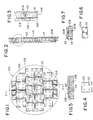
- the segmented substrate comprises in general a plurality of detachable TiN coated molybdenum segments (mesa segments) 102 and 104, attached with TZM (a high strength molybdenum alloy of approximately 0.5% titanium, 0.08% zirconium, 0.01% - 0.04% carbon, and the remainder molybdenum) screw fasteners 206 to a TiN coated molybdenum base plate 108 via bore holes 110 in the base plate 108, and preferably threaded bores 112 in the mesa segments 102.
- TZM high strength molybdenum alloy of approximately 0.5% titanium, 0.08% zirconium, 0.01% - 0.04% carbon, and the remainder molybdenum
- the mesa segments include a plurality of nominally half inch by half inch squares 104 and a plurality of nominally one inch by one inch squares 102 arrayed to fill the area available on the six inch diameter molybdenum base plate 108.
- the mesa segments are typically approximately 0.2 inches in height (thickness), and are preferably separated from each other by grooves of approximately 0.05 inches in width.
- a thin layer of 0.005 inch GRAFOIL 314 which is in turn covered by a 0.001 inch foil of molybdenum 316 is installed over the surface of base plate 108 between the mesa segments 102 and 104 and the base plate 108.
- the thin layers are intended to improve the reliability of the heat transfer between the segments 102 and 104 and the base plate 108, and the thin GRAFOIL and molybdenum layers serve tension on the fasteners 206.
- the GRAFOIL interlayer is somewhat compressible and thereby accommodates local material asperities which might otherwise make repeatable contact problematic.
- the screw tension at operating temperature can be varied by adjusting the thickness of the GRAFOIL interlayer 314.
- the thin layer of molybdenum foil 316 is placed on top of the GRAFOIL layer 314 to avoid any contamination of the diamond from the GRAFOIL.
- the GRAFOIL/molybdenum interface 318 was found to perform well.
- the screw fasteners 206 remained tight through the run, the thermal resistance appeared to be consistent from segment to segment, and the segments 102 and 104 were easily removed at the conclusion of the run.
- a copper layer will also improve the reliability of the heat transfer between the segments 102 and 104 and the base plate 108, and will also maintain tension on the fasteners 206. In addition, as copper will become soft at the deposition temperature, the copper layer will also accommodate local material asperities.
- additional bore holes 111 are provided for attaching the base plate 108 to a rotation means (not shown).
- a centering hole 113 is also provided at the center of the lower surface of base plate 108 for attachment to a rotating spindle or pin (not shown).
- a graphite spacer 115 may be added to maintain heat conductivity through the base plate 108 and segments 102 and 104 to a heat extraction system (not shown).
- the graphite spacer disk 115 will prevent the fasteners 206 from loosening and releasing the segments 102 and 104.
- Figures 5 through 7 illustrate in greater detail the structure of mesa segments 102 and 104, and their attachment to base plate 108 by means of screw fasteners 206 via the bore holes 110 in the base plate and the bores 112 in mesa segments 102 and 104.
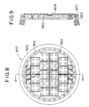
- Figures 8 and 9 show a variation of the above described arrangement for a segmented substrate 800, fabricated in a dished shape, where the segment supporting base plate 808 has an outer diameter curved upward out of the plane of the central region 820.
- This modification may improve deposition rate of diamond film through enhanced interaction of the plasma beam with the substrate along the gas flow path, increasing the effective substrate area which can be coated for a given plasma torch size, and by providing a means of controlling the thickness profile of the deposited diamond through adjustments to the base plate shape.
- 8 and 9 is formed by adding a cylindrical ring 822 to the outer diameter 924 of the standard base plate design 100, shown in Figure 1, and by supporting a ring of segments 826, either normal to or at some angle to the plane of base plate 108. This also increases the deposition surface and thus the eventual yield of the process.
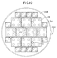
- Figure 10 is an enlarged schematic of a segmented substrate 1000 having a base plate 1008 which is smaller than the mandrel of Fig. 1.
- the segmented substrate 1000 of Fig. 10 has a different array of mesa segments, with additional nominal half inch by half inch segments 104 and fewer nominal one inch by one inch segments 102.
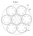
- Figure 11 is plan view of a segmented substrate 1100 having a base plate 1108 which is slightly greater than 7.5 inches in diameter.
- the circular segments 1199 which are coupled to the base plate by fasteners 1106 are each nominally 2.5 inches in diameter. It will be appreciated that the advantage of the array of circular segments of Figure 11 are advantageous in that it is often easier to generate a circular segment rather than providing slightly rounded edges to substantially square or polygonal segments as may be seen by close examination of Figures 1, 8 and 10.
- the advantages of the segmented substrate arrangement of the invention include reductions in yield losses due to lifting, because lifting is reduced when the longest dimension of the individual diamond surface is reduced.
- a lift on any individual segment will not be transferred to adjacent segments. This will allow even runs which experience some lifting to continue to completion, producing an increased yield of diamond at the intended thickness.
- An additional advantage of the invention is that the yield will increase due to a reduction of losses due to cracking. Again, cracking is reduced as a result of reducing the individual diamond coupon size, and thereby minimizing intrinsic stresses. In particular, the smaller diamond segments will experience a smaller release of strain energy on cool-down and separation from the substrate, thereby increasing the percentage of intact squares produced; i.e., yield. Cracking at the corners of the segments are substantially prevented by avoiding sharp corners on the closely spaced segments, and providing fully radiussed corners on the segments.
- the distance between mesas should be kept small. However, at the same time, it is desirable to minimize any tendency for the diamond to grow across the gaps between segments, thereby potentially transferring lifts from one segment to the next. Thus, the distance of 0.05 inches' between mesas (i.e., groove width) has been found as a suitable compromise, although other distances can be used.
- the first trial with the seven and a half inch segmented substrate using the same deposition parameters resulted in a mass deposition rate of 0.46 grams per hour, an increase of nearly sixty percent.
- the average linear deposition rate is reduced to 6.4 microns per hour because of the larger area being coated.
- the base plate could be formed from TZM, tungsten, graphite, or almost any other refractory material.
- a titanium nitride coated molybdenum mandrel substrate has been disclosed, a titanium carbonitride coated molybdenum mandrel substrate may also be used.
- each mesa may be provided, if desired with a band as disclosed in co-owned copending U.S. Serial No. 08/388, 788 equivalent to EP 727 507 A.
Landscapes
- Chemical & Material Sciences (AREA)
- Engineering & Computer Science (AREA)
- Chemical Kinetics & Catalysis (AREA)
- General Chemical & Material Sciences (AREA)
- Materials Engineering (AREA)
- Mechanical Engineering (AREA)
- Metallurgy (AREA)
- Organic Chemistry (AREA)
- Inorganic Chemistry (AREA)
- Plasma & Fusion (AREA)
- Physics & Mathematics (AREA)
- Crystals, And After-Treatments Of Crystals (AREA)
- Chemical Vapour Deposition (AREA)
Claims (25)
- Dispositif pour la fabrication d'un film de diamant autoporteur du type comprenant un mandrin présentant une plaque de base et plusieurs surfaces de dépôt espacées mesa, dans lequel :
ledit mandrin comprend les segments mesa sur lesquels sont établies des surfaces de dépôt mesa, lesdits segments mesa étant fixés de manière réversible à ladite plaque de base dudit mandrin. - Dispositif selon la revendication 1, dans lequel:
ladite plaque de base est circulaire. - Dispositif selon la revendication 2, dans lequel :
ladite plaque de base est adaptée pour être fixée à un moyen adapté pour faire tourner ladite plaque par rapport à un axe central de ladite plaque de base. - Dispositif selon la revendication 1, dans lequel :
ladite plaque de base est faite de molybdène. - Dispositif selon la revendication 1, dans lequel :
lesdits segments mesa sont fabriqués à partir de molybdène, et lesdites surfaces de dépôt comprennent des films de nitrure de titane sur lesdits segments mesa en molybdène. - Dispositif selon la revendication 5, dans lequel :
lesdits segments mesa sont fabriqués à partir d'un alliage de molybdène. - Dispositif selon la revendication 1, dans lequel :
ladite plaque de base est circulaire, et lesdits segments mesa sont sensiblement polygonaux. - Dispositif selon la revendication 7, dans lequel :
lesdits segments mesa présentent une configuration sensiblement quadrilatérale. - Dispositif selon la revendication 7, dans lequel :
lesdits segments mesa présentent des coins arrondis. - Dispositif selon la revendication 2, dans lequel :
lesdits segments mesa présentent une configuration sensiblement circulaire. - Dispositif selon la revendication 8, dans lequel :
un premier segment mesa présente une première dimension, et un second segment mesa présente une seconde dimension différente de ladite première dimension. - Dispositif selon la revendication 1, dans lequel:
ladite plaque de base présente un anneau cylindrique autour de sa périphérie, ledit anneau cylindrique fournissant une zone pour des surfaces de dépôt mesa additionnelles. - Dispositif selon la revendication 12, dans lequel :
ledit anneau cylindrique est disposé de manière sensiblement perpendiculaire au plan de ladite plaque de base. - Dispositif selon la revendication 12, dans lequel:
ledit anneau cylindrique est disposé selon un angle vers l'extérieur à partir du plan de ladite plaque de base. - Dispositif selon la revendication 1, dans lequel :
ledit mandrin comprend au moins une couche flexible conductrice de la chaleur interposée entre lesdits segments mesa et ladite plaque de base. - Dispositif selon la revendication 15, dans lequel :
ladite couche flexible conductrice de la chaleur comprend une feuille de cuivre. - Dispositif selon la revendication 15, dans lequel :
ladite couche flexible, conductrice de la chaleur comprend une couche de tissu de graphite. - Dispositif selon la revendication 17, dans lequel :
ladite couche flexible, conductrice de la chaleur comprend en outre une couche de feuille de molybdène. - Dispositif selon la revendication 1, dans lequel :
lesdites surfaces de dépôt espacées sont séparées par des distances d'environ 0,127 cm (0,05 pouces). - Procédé de fabrication d'un film de diamant autoporteur, du type comprenant:a) la fourniture d'un mandrin qui inclut une plaque de base présentant plusieurs surfaces de dépôt espacées mesa ou "segments" sur lesquels le diamant doit être déposé comme un film ; dans lequel lesdits segments mesa sont fixés de manière réversible à ladite plaque de base dudit mandrin ;b) le dépôt du diamant sur une pluralité de surfaces de dépôt espacées mesa pour former une pluralité de films de diamant séparés ; etc) l'enlèvement desdits films de diamant à partir desdites surfaces.
- Procédé selon la revendication 20, dans lequel :
ladite fourniture d'un mandrin comprend la fixation des segments mesa à la plaque de base d'une configuration souhaitée. - Procédé selon la revendication 21, dans lequel :ladite plaque de base est circulaire, etledit dépôt de diamant est réalisé tandis que ladite plaque de base effectue une rotation par rapport à son axe central.
- Procédé selon la revendication 21, dans lequel :
lesdits segments mesa sont de forme polygonale. - Procédé selon la revendication 21, dans lequel :
lesdits segments mesa sont de forme circulaire. - Procédé selon la revendication 21, dans lequel :
ladite fourniture d'un mandrin comprend la fourniture de la plaque de base avec un anneau cylindrique autour de sa périphérie.
Applications Claiming Priority (2)
| Application Number | Priority Date | Filing Date | Title |
|---|---|---|---|
| US08/473,197 US5762715A (en) | 1995-06-07 | 1995-06-07 | Segmented substrate for improved ARC-JET diamond deposition |
| US473197 | 1995-06-07 |
Publications (2)
| Publication Number | Publication Date |
|---|---|
| EP0751237A1 EP0751237A1 (fr) | 1997-01-02 |
| EP0751237B1 true EP0751237B1 (fr) | 2001-08-01 |
Family
ID=23878583
Family Applications (1)
| Application Number | Title | Priority Date | Filing Date |
|---|---|---|---|
| EP96201500A Expired - Lifetime EP0751237B1 (fr) | 1995-06-07 | 1996-05-29 | Substrat segmenté pour la déposition du diamant par le procédé arc-jet |
Country Status (5)
| Country | Link |
|---|---|
| US (2) | US5762715A (fr) |
| EP (1) | EP0751237B1 (fr) |
| JP (1) | JP2937863B2 (fr) |
| CA (1) | CA2177012C (fr) |
| DE (1) | DE69614197D1 (fr) |
Cited By (1)
| Publication number | Priority date | Publication date | Assignee | Title |
|---|---|---|---|---|
| CN105695831A (zh) * | 2016-03-21 | 2016-06-22 | 中南大学 | 一种超高导热连续金刚石骨架增强复合材料及制备方法 |
Families Citing this family (14)
| Publication number | Priority date | Publication date | Assignee | Title |
|---|---|---|---|---|
| US6533869B1 (en) * | 1995-02-15 | 2003-03-18 | Saint-Gobain/Norton Industrial Ceramics Corporation | Apparatus and method for making free standing diamond |
| CA2247818A1 (fr) * | 1997-11-04 | 1999-05-04 | Bruce E. Foye | Mandrin pour depot diamantaire en deux parties avec anneau de graphite |
| US6261693B1 (en) | 1999-05-03 | 2001-07-17 | Guardian Industries Corporation | Highly tetrahedral amorphous carbon coating on glass |
| US6312808B1 (en) | 1999-05-03 | 2001-11-06 | Guardian Industries Corporation | Hydrophobic coating with DLC & FAS on substrate |
| US6368664B1 (en) | 1999-05-03 | 2002-04-09 | Guardian Industries Corp. | Method of ion beam milling substrate prior to depositing diamond like carbon layer thereon |
| US6461731B1 (en) | 1999-05-03 | 2002-10-08 | Guardian Industries Corp. | Solar management coating system including protective DLC |
| US6447891B1 (en) | 1999-05-03 | 2002-09-10 | Guardian Industries Corp. | Low-E coating system including protective DLC |
| US6280834B1 (en) | 1999-05-03 | 2001-08-28 | Guardian Industries Corporation | Hydrophobic coating including DLC and/or FAS on substrate |
| US6475573B1 (en) | 1999-05-03 | 2002-11-05 | Guardian Industries Corp. | Method of depositing DLC inclusive coating on substrate |
| US6335086B1 (en) | 1999-05-03 | 2002-01-01 | Guardian Industries Corporation | Hydrophobic coating including DLC on substrate |
| US6277480B1 (en) | 1999-05-03 | 2001-08-21 | Guardian Industries Corporation | Coated article including a DLC inclusive layer(s) and a layer(s) deposited using siloxane gas, and corresponding method |
| DE10149588B4 (de) * | 2001-10-08 | 2017-09-07 | Oerlikon Trading Ag, Trübbach | Verfahren zur Diamantbeschichtung von Substraten |
| CN103276265B (zh) * | 2013-06-09 | 2015-04-01 | 北京科技大学 | 金刚石自支撑膜-金刚石颗粒-金属复合材料的制备方法 |
| GB201701173D0 (en) * | 2017-01-24 | 2017-03-08 | Element Six Tech Ltd | Synthetic diamond plates |
Family Cites Families (14)
| Publication number | Priority date | Publication date | Assignee | Title |
|---|---|---|---|---|
| US4485759A (en) * | 1983-01-19 | 1984-12-04 | Multi-Arc Vacuum Systems Inc. | Planetary substrate support apparatus for vapor vacuum deposition coating |
| CA2034440A1 (fr) * | 1990-02-13 | 1991-08-14 | Thomas R. Anthony | Pieces diamantees par dcpv et methode de fabrication |
| US5256205A (en) * | 1990-05-09 | 1993-10-26 | Jet Process Corporation | Microwave plasma assisted supersonic gas jet deposition of thin film materials |
| EP0458342A1 (fr) * | 1990-05-25 | 1991-11-27 | Idemitsu Petrochemical Company Limited | Méthode pour obtenir un object revêtu d'un film de diamant |
| US5256206A (en) * | 1990-08-07 | 1993-10-26 | General Electric Company | CVD diamond for coating twist drills |
| US5204145A (en) * | 1991-03-04 | 1993-04-20 | General Electric Company | Apparatus for producing diamonds by chemical vapor deposition and articles produced therefrom |
| US5204144A (en) * | 1991-05-10 | 1993-04-20 | Celestech, Inc. | Method for plasma deposition on apertured substrates |
| JP3350929B2 (ja) * | 1991-05-10 | 2002-11-25 | セレステック,インコーポレーテッド | プラズマ堆積方法及び装置 |
| US5342660A (en) * | 1991-05-10 | 1994-08-30 | Celestech, Inc. | Method for plasma jet deposition |
| GB9123331D0 (en) * | 1991-11-04 | 1991-12-18 | De Beers Ind Diamond | Apparatus for depositing a material on a substrate by chemical vapour deposition |
| US5314652A (en) * | 1992-11-10 | 1994-05-24 | Norton Company | Method for making free-standing diamond film |
| US5391229A (en) * | 1993-07-26 | 1995-02-21 | General Electric Company | Apparatus for chemical vapor deposition of diamond including graphite substrate holders |
| US5486380A (en) * | 1993-12-30 | 1996-01-23 | Saint-Gobain/Norton Industrial Ceramics Corporation | Apparatus and method for depositing a substance on a rotating surface |
| US5587124A (en) * | 1994-07-05 | 1996-12-24 | Meroth; John | Method of making synthetic diamond film with reduced bowing |
-
1995
- 1995-06-07 US US08/473,197 patent/US5762715A/en not_active Expired - Fee Related
-
1996
- 1996-05-21 CA CA002177012A patent/CA2177012C/fr not_active Expired - Fee Related
- 1996-05-29 EP EP96201500A patent/EP0751237B1/fr not_active Expired - Lifetime
- 1996-05-29 DE DE69614197T patent/DE69614197D1/de not_active Expired - Lifetime
- 1996-06-07 JP JP8146188A patent/JP2937863B2/ja not_active Expired - Lifetime
-
1997
- 1997-09-18 US US08/933,328 patent/US5849228A/en not_active Expired - Fee Related
Cited By (1)
| Publication number | Priority date | Publication date | Assignee | Title |
|---|---|---|---|---|
| CN105695831A (zh) * | 2016-03-21 | 2016-06-22 | 中南大学 | 一种超高导热连续金刚石骨架增强复合材料及制备方法 |
Also Published As
| Publication number | Publication date |
|---|---|
| US5762715A (en) | 1998-06-09 |
| JPH0940495A (ja) | 1997-02-10 |
| DE69614197D1 (de) | 2001-09-06 |
| US5849228A (en) | 1998-12-15 |
| EP0751237A1 (fr) | 1997-01-02 |
| JP2937863B2 (ja) | 1999-08-23 |
| CA2177012A1 (fr) | 1996-12-08 |
| CA2177012C (fr) | 2000-10-17 |
Similar Documents
| Publication | Publication Date | Title |
|---|---|---|
| EP0751237B1 (fr) | Substrat segmenté pour la déposition du diamant par le procédé arc-jet | |
| JP3150024B2 (ja) | 合成ダイヤモンド膜の製造方法 | |
| EP1358363B1 (fr) | Revetements de diamant sur paroi de reacteur et procede de fabrication de ceux-ci | |
| KR100761592B1 (ko) | 경사진 스퍼터링 타겟 및 그 제조 방법 | |
| EP0633600A1 (fr) | Méthode et appareil pour former des films minces | |
| KR0146410B1 (ko) | Ti-TiN 적층막의 성막방법 및 마그네트론 캐소드 | |
| JPH10229058A (ja) | コーティング付き堆積チャンバ装置 | |
| US5391229A (en) | Apparatus for chemical vapor deposition of diamond including graphite substrate holders | |
| EP0727507B1 (fr) | Dispositif et procédé pour la fabrication des lames de diamant | |
| JP2000514720A (ja) | 材料切削加工するための工具 | |
| EP0747504B1 (fr) | Support rotatif pour plaquettes de coupe à revêtir avec du diamant par le procédé arc-jet | |
| JPH11158617A (ja) | スパッタリング方法およびスパッタリング装置 | |
| US6443092B1 (en) | Apparatus for synthesizing diamond film by DC PACVD | |
| CN114905419B (zh) | 一种具有保护层的切割片及其制备方法 | |
| KR102207607B1 (ko) | 다음극 직류전원 플라즈마 cvd 다이아몬드 성장 장치 | |
| EP0916745A1 (fr) | Mandrin en deux parties avec bague en graphite pour le dépÔt de diamant | |
| KR100347422B1 (ko) | 텅스텐탄화물-티타늄질화물 초격자 코팅막과 그의 제조장치 및 방법 | |
| EP1815042A2 (fr) | Surfaces recouvertes de diamant | |
| JP2009013003A (ja) | ダイヤモンド製造方法及び製造装置 | |
| Spalvins | Morphology of gold and copper ion-plated coatings | |
| JP2019012786A (ja) | 研削装置および研削方法 | |
| KR20030001801A (ko) | 기상화학증착법에 의한 구상의 다이아몬드 분말 합성장치및 이를 이용한 구상의 다이아몬드 합성방법 |
Legal Events
| Date | Code | Title | Description |
|---|---|---|---|
| PUAI | Public reference made under article 153(3) epc to a published international application that has entered the european phase |
Free format text: ORIGINAL CODE: 0009012 |
|
| AK | Designated contracting states |
Kind code of ref document: A1 Designated state(s): DE FR GB |
|
| 17P | Request for examination filed |
Effective date: 19970226 |
|
| 17Q | First examination report despatched |
Effective date: 19980826 |
|
| RAP1 | Party data changed (applicant data changed or rights of an application transferred) |
Owner name: SAINT-GOBAIN INDUSTRIAL CERAMICS, INC. |
|
| GRAG | Despatch of communication of intention to grant |
Free format text: ORIGINAL CODE: EPIDOS AGRA |
|
| GRAG | Despatch of communication of intention to grant |
Free format text: ORIGINAL CODE: EPIDOS AGRA |
|
| GRAH | Despatch of communication of intention to grant a patent |
Free format text: ORIGINAL CODE: EPIDOS IGRA |
|
| GRAH | Despatch of communication of intention to grant a patent |
Free format text: ORIGINAL CODE: EPIDOS IGRA |
|
| GRAA | (expected) grant |
Free format text: ORIGINAL CODE: 0009210 |
|
| AK | Designated contracting states |
Kind code of ref document: B1 Designated state(s): DE FR GB |
|
| PG25 | Lapsed in a contracting state [announced via postgrant information from national office to epo] |
Ref country code: FR Free format text: LAPSE BECAUSE OF FAILURE TO SUBMIT A TRANSLATION OF THE DESCRIPTION OR TO PAY THE FEE WITHIN THE PRESCRIBED TIME-LIMIT Effective date: 20010801 |
|
| REF | Corresponds to: |
Ref document number: 69614197 Country of ref document: DE Date of ref document: 20010906 |
|
| PG25 | Lapsed in a contracting state [announced via postgrant information from national office to epo] |
Ref country code: DE Free format text: LAPSE BECAUSE OF FAILURE TO SUBMIT A TRANSLATION OF THE DESCRIPTION OR TO PAY THE FEE WITHIN THE PRESCRIBED TIME-LIMIT Effective date: 20011103 |
|
| EN | Fr: translation not filed | ||
| REG | Reference to a national code |
Ref country code: GB Ref legal event code: IF02 |
|
| PG25 | Lapsed in a contracting state [announced via postgrant information from national office to epo] |
Ref country code: GB Free format text: LAPSE BECAUSE OF NON-PAYMENT OF DUE FEES Effective date: 20020529 |
|
| PLBE | No opposition filed within time limit |
Free format text: ORIGINAL CODE: 0009261 |
|
| STAA | Information on the status of an ep patent application or granted ep patent |
Free format text: STATUS: NO OPPOSITION FILED WITHIN TIME LIMIT |
|
| 26N | No opposition filed | ||
| GBPC | Gb: european patent ceased through non-payment of renewal fee |
Effective date: 20020529 |