EP0751040B1 - Feu de signalisation à moyens de montage perfectionnés pour véhicule automobile - Google Patents
Feu de signalisation à moyens de montage perfectionnés pour véhicule automobile Download PDFInfo
- Publication number
- EP0751040B1 EP0751040B1 EP19960401399 EP96401399A EP0751040B1 EP 0751040 B1 EP0751040 B1 EP 0751040B1 EP 19960401399 EP19960401399 EP 19960401399 EP 96401399 A EP96401399 A EP 96401399A EP 0751040 B1 EP0751040 B1 EP 0751040B1
- Authority
- EP
- European Patent Office
- Prior art keywords
- light unit
- screw
- unit according
- indicating light
- screw fastening
- Prior art date
- Legal status (The legal status is an assumption and is not a legal conclusion. Google has not performed a legal analysis and makes no representation as to the accuracy of the status listed.)
- Expired - Lifetime
Links
- 230000011664 signaling Effects 0.000 title description 8
- 238000007789 sealing Methods 0.000 claims description 7
- 230000006835 compression Effects 0.000 claims description 2
- 238000007906 compression Methods 0.000 claims description 2
- 238000003032 molecular docking Methods 0.000 description 3
- 230000001419 dependent effect Effects 0.000 description 1
- 230000006866 deterioration Effects 0.000 description 1
- 239000006260 foam Substances 0.000 description 1
- 239000011521 glass Substances 0.000 description 1
- 238000012423 maintenance Methods 0.000 description 1
- 238000004519 manufacturing process Methods 0.000 description 1
- 239000002184 metal Substances 0.000 description 1
- 230000003287 optical effect Effects 0.000 description 1
- 229920001296 polysiloxane Polymers 0.000 description 1
- 230000008439 repair process Effects 0.000 description 1
Images


Classifications
-
- B—PERFORMING OPERATIONS; TRANSPORTING
- B60—VEHICLES IN GENERAL
- B60Q—ARRANGEMENT OF SIGNALLING OR LIGHTING DEVICES, THE MOUNTING OR SUPPORTING THEREOF OR CIRCUITS THEREFOR, FOR VEHICLES IN GENERAL
- B60Q1/00—Arrangement of optical signalling or lighting devices, the mounting or supporting thereof or circuits therefor
- B60Q1/26—Arrangement of optical signalling or lighting devices, the mounting or supporting thereof or circuits therefor the devices being primarily intended to indicate the vehicle, or parts thereof, or to give signals, to other traffic
- B60Q1/2619—Arrangement of optical signalling or lighting devices, the mounting or supporting thereof or circuits therefor the devices being primarily intended to indicate the vehicle, or parts thereof, or to give signals, to other traffic built in the vehicle body
- B60Q1/2623—Details of the fastening means
- B60Q1/2626—Screw-nut fasteners
-
- B—PERFORMING OPERATIONS; TRANSPORTING
- B60—VEHICLES IN GENERAL
- B60Q—ARRANGEMENT OF SIGNALLING OR LIGHTING DEVICES, THE MOUNTING OR SUPPORTING THEREOF OR CIRCUITS THEREFOR, FOR VEHICLES IN GENERAL
- B60Q1/00—Arrangement of optical signalling or lighting devices, the mounting or supporting thereof or circuits therefor
- B60Q1/26—Arrangement of optical signalling or lighting devices, the mounting or supporting thereof or circuits therefor the devices being primarily intended to indicate the vehicle, or parts thereof, or to give signals, to other traffic
- B60Q1/2619—Arrangement of optical signalling or lighting devices, the mounting or supporting thereof or circuits therefor the devices being primarily intended to indicate the vehicle, or parts thereof, or to give signals, to other traffic built in the vehicle body
- B60Q1/2649—Arrangement of optical signalling or lighting devices, the mounting or supporting thereof or circuits therefor the devices being primarily intended to indicate the vehicle, or parts thereof, or to give signals, to other traffic built in the vehicle body with provision for pre-mounting or temporary holding the device before or during final mounting
-
- B—PERFORMING OPERATIONS; TRANSPORTING
- B60—VEHICLES IN GENERAL
- B60Q—ARRANGEMENT OF SIGNALLING OR LIGHTING DEVICES, THE MOUNTING OR SUPPORTING THEREOF OR CIRCUITS THEREFOR, FOR VEHICLES IN GENERAL
- B60Q1/00—Arrangement of optical signalling or lighting devices, the mounting or supporting thereof or circuits therefor
- B60Q1/26—Arrangement of optical signalling or lighting devices, the mounting or supporting thereof or circuits therefor the devices being primarily intended to indicate the vehicle, or parts thereof, or to give signals, to other traffic
- B60Q1/2619—Arrangement of optical signalling or lighting devices, the mounting or supporting thereof or circuits therefor the devices being primarily intended to indicate the vehicle, or parts thereof, or to give signals, to other traffic built in the vehicle body
- B60Q1/2653—Arrangement of optical signalling or lighting devices, the mounting or supporting thereof or circuits therefor the devices being primarily intended to indicate the vehicle, or parts thereof, or to give signals, to other traffic built in the vehicle body with arrangement for sealing the device with respect to the vehicle body, or for concealing gaps between the device and the vehicle body
Definitions
- the present invention relates generally to motor vehicle signaling lights.
- a problem posed with this type of mounting is that that, for reasons including inaccuracies or manufacturing tolerance, docking or sealing between fire and edges of opening may be poorly insured when the fire itself and the wall in which is the opening is rigid.
- the device taught by this document does not prevent the application of excessive loads to the headlamp, especially when the coils of the spring come to bear against each other. So, this is here again “judged” that the operator will have to perform the mounting without risk of damaging the projector or its fixation. So it would be out of the question to use this known device, as is, in traffic lights modern, with plastic case, which are more fragile than 1940s sheet metal spotlights.
- the present invention aims to solve the drawback aforementioned in the specific field of traffic lights, and to propose a signaling light whose fixing can be secured with a screw stop without incurring the risk of imparting stress and / or wall stress excessive likely to deteriorate or even break.
- the present invention relates to a fire motor vehicle signage as defined in claim 1.
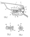
- a rear flap of a vehicle which includes a skin 1 defining with a lining 2 a cavity in which is placed a traffic light.
- the skin 1 has a large, generally horizontal wall or slightly oblique and a small vertical wall directed towards the rear of the vehicle and in which a opening 11 surrounded by edges defining a support for a sealing element 12 of the foam seal type, or silicone.
- the traffic light which in this case is a traffic light additional rear stop, raised or below the rear window, is generally designated by the reference 3. It includes a base 33 open towards the rear (towards the right in Figure 1) and housing one or more sources 34, in this case a series of diodes electroluminescent, and an optical plate 32 disposed between the sources and the opening of the base. This opening is covered by a closing light 31 and is surrounded by a collar on which the inside edges of the seeing come to take support.
- This collar is also used, when the fire is set in place, compressing the sealing element 12 between said flange and the edge of the opening 11 formed in the skin 1, as illustrated.
- the base is extended towards the interior of the vehicle (to the left in Figure 1) by a frame comprising a horizontal part 35 and a vertical part descending 36 in which an opening is formed circular.
- the lining of the vehicle has a recess 21 including a bottom wall 22 has an opening aligned with the opening of the part 36.
- a light mounting screw generally indicated in 5 has a wide head 51 and a threaded rod 52.
- This threaded rod is engaged by screwing in a screw barrel element, generally designated by the reference 4 and shown in more detail in FIGS. 2 and 3.
- This element comprises a cylindrical barrel 42 and at a end of the barrel, a radial flange 41 in the part upper of which is formed a flat 44.
- a internal thread 43 receiving the threaded rod 52 of the screw.
- the outside diameter of the barrel 42 is slightly smaller the inside diameter of the opening formed in the part 36 secured to the base, so that it can slide in this opening in which he is engaged, while he is greater than the inside diameter of the opening formed in the wall 22 of the lining.
- a compression spring 6 is prisoner between the collar 41 of the barrel 4 and the part of frame 36 secured to the base.
- the signaling light described above is mounted by the outside of the skin 1, by a translational movement inward (to the left in Figure 1), the element seal 12 being previously installed.
- a frank screwing stop is defined during of the coming into support of the end of the barrel opposite to its flange against the face of the wall 22 which is in vis-à-vis, and by the coming into abutment of the screw head 51 against the wall 22.
- this fire has as a source an incandescent lamp 34.
- the base 33 is ends, at its opening, with an outer rim curve which receives outside the edge of the sight glass 31 and which comes from the outside to cover a flexible seal 12 similar to that of FIG. 1.
- the lining 2 is bordered by a covering 7, these two elements being substantially spaced from each other at the rear (to the left in the figures) of the light.
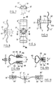
- the posterior part of the base 33 includes a part 36 'defining a channel transverse delimited at its two longitudinal ends by a ledge, respectively 36a, 36b, this channel housing a sinuous leaf spring 6 'pierced with a central hole receiving a 5 'screw provided with a head 51 on the inner side of the fire and a threaded rod 52 projecting towards the rear of the fire.
- This rod 52 passes through another opening formed in the lining 2, a nut 55 with a washer 56 and a lock nut 54 for securing the light.
- the effort of tightening applied at nut 55 is transmitted to fire by means of the leaf spring 6 ', which allows limit the stresses, while the lock nut 54 defines a frank stop for screwing the nut 55.
- the base of the fire comprises, in rearward projection, two flexible legs 37a, 37b ( Figure 5) provided with teeth at their free end attachment 38a, 38b which are engaged in openings 21a, 21b formed in the lining 2, to ensure a prepositioning and / or a pre-maintenance of the fire before screwing.
- the position of the lock nut 54 is chosen so as to optimally adjust the stress transmitted to the fire by the leaf spring, this solicitation being determined in particular according to the nature and dimensions of joint 12 and deviations that we can expect.
- leaf spring 6 ' there is shown in detail of the leaf spring 6 '.
- it includes vicinity of the hole for the 5 'screw two wings folded at 90 ° with respect to its general plan and whose spacing 61 is such that they prevent the rotation of the screw head 51. It as a result that the nuts 54 and 55 can be screwed in without have to block the rotation of the screw by other means.
- the 5 "screw includes a head 51, a first threaded portion 52a adjacent to the head and a second threaded portion 52b, of smaller diameter, at its free end.
- the first threaded part 52a cooperates with a thread formed directly in the opening provided in the wall 2, while the second threaded part 52b cooperates with a thread or with a punch formed in the leaf spring 6 '.
- the part 52a defines the end stop of screwing, when the head 51 comes to bear against the wall 2, while the part 52b ensures the solicitation of the leaf spring 6 'by 5 "screw.
- These means include in this case a folding to about 90 ° from the free ends 64 'of the blade, which are thus trapped in cavities 39 'formed in fittings 38 'integral with the base while being able to move in these cavities a certain distance.
- leaf spring 6 has the general shape of a lyre, with two branches 63 generally parallel whose mutual spacing can vary.
- Each of these branches is provided at its end free of a hooking tooth 64 able to cooperate with a offset 39 formed on a respective layout 38 secured to the base and provided in a suitable location.
- the distance between the two branches 63 can vary thanks to the elasticity of the leaf spring, to adapt to different configurations of basement. So, in Figure 10b, the ends of the two branches are engaged in a single cavity with two recesses formed in an arrangement 38 of the base which is different from that of Figure 10a.
- the fire according to the present invention can be installed on a rear shutter, but also on any fixed part of the vehicle.
Landscapes
- Engineering & Computer Science (AREA)
- Mechanical Engineering (AREA)
- Lighting Device Outwards From Vehicle And Optical Signal (AREA)
Description
Claims (13)
- Feu de signalisation (3) pour véhicule automobile, du type comprenantcaractérisé en ce queun socle (33) abritant une source lumineuse (34) et fermé par un voyant (31), le feu prenant appui par un rebord (37) contre le bord d'une ouverture formée dans une paroi rigide (1) du véhicule etun moyen de fixation par vissage (5,4; 5',54,55) agissant au niveau du socle (33) pour presser ledit rebord contre ledit bord, etun moyen élastique (6;6') opérant entre le moyen de fixation par vissage et le socle pour limiter les sollicitations transmises au feu
le moyen de fixation par vissage comprend un moyen (4;54) formant butée de vissage pour empêcher l'application de sollicitations excessives au feu lors du vissage du moyen de fixation. - Feu de signalisation selon la revendication 1, caractérisé en ce qu'un joint d'étanchéité (12) est interposé entre le bord de l'ouverture et le rebord du feu.
- Feu de signalisation selon l'une des revendications 1 et 2, caractérisé en ce qu'il comprend des moyens (37a, 37b) de prépositionnement et/ou de prémaintien du feu avant mise en oeuvre du moyen de vissage.
- Feu de signalisation selon l'une des revendications 1 à 3, caractérisé en ce que le moyen de fixation par vissage comprend une vis (5) et un canon taraudé (4) situés de part et d'autre d'une autre paroi (22) du véhicule, la vis traversant une ouverture formée dans ladite autre paroi, en ce que ledit canon (4) forme butée de vissage et en ce que le moyen élastique est formé par un ressort de compression (6) interposé entre une première zone d'appui (41) formée sur le canon et une deuxième zone d'appui (36) solidaire du socle (33) du feu.
- Feu de signalisation selon la revendication 4, caractérisé en ce que le socle comprend d'un seul tenant un prolongement dont une première partie (35) coopère avec le canon (4) pour empêcher sa rotation et dont une seconde partie (36) forme ladite deuxième zone d'appui.
- Feu de signalisation selon l'une des revendications 4 et 5, caractérisé en ce que ladite première zone d'appui du ressort (6) est formée par une collerette (41) d'un seul tenant avec le canon (4), le ressort étant disposé autour du canon.
- Feu de signalisation selon l'une des revendications 1 à 3, caractérisé en ce que le moyen élastique est formé par une lame-ressort allongée (6') traversée par la vis (5') dans une partie centrale et en appui contre le socle dans des parties d'extrémité.
- Feu de signalisation selon la revendication 7, caractérisé en ce que les parties d'extrémité de la lame-ressort possèdent des moyens d'accrochage sur le socle.
- Feu de signalisation selon l'une des revendications 1 à 3, caractérisé en ce que le moyen élastique est formé par une lame-ressort (6") en forme générale de lyre traversée par la vis (5') dans une partie centrale et comportant deux branches généralement parallèles dont des parties d'extrémité sont accrochées sur le socle.
- Feu de signalisation selon l'une des revendications 7 à 9, caractérisé en ce que le moyen de vissage comprend une vis (5') associée à un écrou (55) et à un contre-écrou (54) situés de part et d'autre d'une autre paroi (2) du véhicule, et en ce que le contre-écrou (54) forme butée de vissage de l'écrou.
- Feu de signalisation selon la revendication 10, caractérisé en ce que la lame-ressort comporte des aménagements pour bloquer la rotation d'une tête (51) de ladite vis (5').
- Feu de signalisation selon l'une des revendications 7 à 9, caractérisé en ce que le moyen de vissage comprend une vis (5") comportant une première partie filetée (52a) coopérant avec une autre paroi (2) du véhicule pour former une butée de vissage, et une seconde partie filetée (52b), de plus petit diamètre, traversant la lame-ressort.
- Feu de signalisation selon l'une des revendications 7 à 12, caractérisé en ce que le socle du feu comprend des pattes flexibles (37a, 37b) à dents (38a, 38b) en saillie vers l'arrière et définissant les moyens de prépositionnement et/ou de prémaintien du feu avant vissage.
Applications Claiming Priority (2)
| Application Number | Priority Date | Filing Date | Title |
|---|---|---|---|
| FR9507720 | 1995-06-27 | ||
| FR9507720A FR2736017B1 (fr) | 1995-06-27 | 1995-06-27 | Feu de signalisation a moyens de montage perfectionnes pour vehicule automobile |
Publications (2)
| Publication Number | Publication Date |
|---|---|
| EP0751040A1 EP0751040A1 (fr) | 1997-01-02 |
| EP0751040B1 true EP0751040B1 (fr) | 2000-08-09 |
Family
ID=9480434
Family Applications (1)
| Application Number | Title | Priority Date | Filing Date |
|---|---|---|---|
| EP19960401399 Expired - Lifetime EP0751040B1 (fr) | 1995-06-27 | 1996-06-25 | Feu de signalisation à moyens de montage perfectionnés pour véhicule automobile |
Country Status (4)
| Country | Link |
|---|---|
| EP (1) | EP0751040B1 (fr) |
| DE (1) | DE69609675T2 (fr) |
| ES (1) | ES2150647T3 (fr) |
| FR (1) | FR2736017B1 (fr) |
Families Citing this family (12)
| Publication number | Priority date | Publication date | Assignee | Title |
|---|---|---|---|---|
| EP0838369B1 (fr) * | 1996-10-23 | 2003-09-03 | Volkswagen Aktiengesellschaft | Combinaison d'un feu ou d'une phare et une pièce de véhicule |
| DE59710464D1 (de) * | 1996-10-23 | 2003-08-28 | Volkswagen Ag | Fahrzeugleuchte oder -scheinwerfer |
| FR2763304B1 (fr) * | 1997-05-14 | 1999-08-06 | Valeo Vision | Dispositif de pre-fixation d'un dispositif d'eclairage ou de signalisation sur une carrosserie de vehicule automobile |
| DE19813596B4 (de) * | 1998-03-27 | 2007-06-28 | Volkswagen Ag | Befestigungsvorrichtung für ein Fahrzeugteil |
| DE19915835A1 (de) * | 1999-04-08 | 2000-10-12 | Bayerische Motoren Werke Ag | Befestigungsanordnung für ein Ausstattungsteil |
| DE19920703C2 (de) * | 1999-05-05 | 2001-03-22 | Fer Fahrzeugelektrik Gmbh | Anordnung zum Befestigen einer Fahrzeugleuchte |
| DE102004031429B4 (de) * | 2003-07-01 | 2009-01-08 | Seat S.A. | Zusätzliche Bremslichtvorrichtung für Fahrzeuge |
| DE102005010188A1 (de) * | 2005-03-05 | 2006-09-07 | Hella Kgaa Hueck & Co. | Leuchte für Fahrzeuge |
| DE102007062435B4 (de) * | 2007-12-20 | 2018-05-03 | Hella Autotechnik Nova, S.R.O. | Befestigungsvorrichtung für eine Leuchteinheit |
| FR2936457B1 (fr) * | 2008-09-26 | 2011-11-25 | Valeo Vision Sas | Dispositif d'eclairage ou de signalisation de vehicule automobile comportant un organe de fixation equipe d'un element elastiquement deformable |
| DE102012022203B4 (de) * | 2012-11-13 | 2019-03-07 | Audi Ag | Befestigungsanordnung mit einer Fahrzeugleuchte und einer Heckklappe |
| FR3045527B1 (fr) * | 2015-12-16 | 2019-05-10 | Compagnie Plastic Omnium | Boitier optique allege pour vehicule automobile |
Family Cites Families (4)
| Publication number | Priority date | Publication date | Assignee | Title |
|---|---|---|---|---|
| FR894131A (fr) * | 1942-04-24 | 1944-12-14 | Bosch Gmbh Robert | Phare encastré par l'avant dans la carrosserie d'un véhicule, notamment d'une automobile |
| FR899047A (fr) * | 1943-10-21 | 1945-05-15 | Dispositif de réglage pour phare disposé dans l'aile d'un véhicule | |
| FR1605006A (fr) * | 1967-12-21 | 1972-08-28 | ||
| US4356539A (en) * | 1979-10-16 | 1982-10-26 | General Electric Company | Vehicle headlamp having an integral buggy spring mounting assembly |
-
1995
- 1995-06-27 FR FR9507720A patent/FR2736017B1/fr not_active Expired - Lifetime
-
1996
- 1996-06-25 DE DE1996609675 patent/DE69609675T2/de not_active Expired - Lifetime
- 1996-06-25 EP EP19960401399 patent/EP0751040B1/fr not_active Expired - Lifetime
- 1996-06-25 ES ES96401399T patent/ES2150647T3/es not_active Expired - Lifetime
Also Published As
| Publication number | Publication date |
|---|---|
| DE69609675T2 (de) | 2001-04-05 |
| FR2736017A1 (fr) | 1997-01-03 |
| FR2736017B1 (fr) | 1997-09-19 |
| ES2150647T3 (es) | 2000-12-01 |
| EP0751040A1 (fr) | 1997-01-02 |
| DE69609675D1 (de) | 2000-09-14 |
Similar Documents
| Publication | Publication Date | Title |
|---|---|---|
| EP0807547B1 (fr) | Fixation de feu sur carrosserie de véhicule automobile, comportant un ressort accordeon | |
| EP0620137A1 (fr) | Projecteur pour véhicule automobile | |
| FR2736017A1 (fr) | Feu de signalisation a moyens de montage perfectionnes pour vehicule automobile | |
| FR2608107A2 (fr) | Dispositif de fixation reglable, notamment pour projecteur de vehicule automobile | |
| EP0679553B1 (fr) | Ensemble pour la fixation ajustable selon trois dimensions d'un dispositif d'éclairage et/ou de signalisation de véhicule automobile | |
| FR2920015A3 (fr) | Structure de vehicule automobile et procede de fixation d'un accessoire | |
| EP2279907A1 (fr) | Dispositif d'éclairage pour véhicule automobile | |
| EP0604306B1 (fr) | Feu plaqué contre une carrosserie de véhicule automobile muni d'un joint d'étanchéité tri-fonction | |
| FR2739816A1 (fr) | Projecteur pour vehicules | |
| FR2796427A1 (fr) | Dispositif de premontage d'un ecrou pour ensemble de fixation du type vis-ecrou | |
| FR2687762A1 (fr) | Projecteur a lentille equipe de moyens de montage de la lentille perfectionnes. | |
| FR2786233A1 (fr) | Dispositif de liaison pour levier pivotant, notamment pedale de frein, et organe de commande associe | |
| FR2748708A1 (fr) | Fixation de feu sur carrosserie de vehicule automobile, comportant un ressort accordeon | |
| FR2711101A1 (fr) | Pièce de montage de la tige de sortie à extrémité sphérique d'un correcteur sur un réflecteur pour projecteur de véhicule automobile. | |
| EP2168810B1 (fr) | Dispositif d'éclairage ou de signalisation comportant des moyens de fixation par cheville d'expansion | |
| FR2698054A1 (fr) | Bloc optique pour véhicule automobile. | |
| EP1655537B1 (fr) | Dispositif projecteur avec élément d'occultation à système de fixation intégré et procédé de fixation d'un élément d'occultation dans un dispositif projecteur | |
| FR2971565A1 (fr) | Systeme de fixation reglable formant entretoise. | |
| EP0586306A2 (fr) | Système de montage réglable d'un dispositif d'éclairage ou de signalisation de véhicule automobile sur une partie fixe solidaire du véhicule et dispositif ainsi équipé | |
| FR2904095A1 (fr) | Dispositif d'eclairage et/ou de signalisation multifonctions a protection thermique pour vehicule. | |
| FR2711196A1 (fr) | Ecrou encagé à montage sur un rail ou analogue et assemblage obtenu à l'aide de cet écrou. | |
| EP1277617A2 (fr) | Dispositif de fixation d'un rétroviseur extérieur sur un véhicule automobile | |
| WO2023186942A1 (fr) | Module lumineux comportant un dispositif de reglage de l'orientation d'un faisceau limineux | |
| FR2936457A1 (fr) | Dispositif d'eclairage ou de signalisation de vehicule automobile comportant un organe de fixation equipe d'un element elastiquement deformable | |
| EP4500076A1 (fr) | Module lumineux comportant un dispositif de reglage de l'orientation d'un faisceau lumineux a coupure |
Legal Events
| Date | Code | Title | Description |
|---|---|---|---|
| PUAI | Public reference made under article 153(3) epc to a published international application that has entered the european phase |
Free format text: ORIGINAL CODE: 0009012 |
|
| AK | Designated contracting states |
Kind code of ref document: A1 Designated state(s): DE ES GB IT |
|
| 17P | Request for examination filed |
Effective date: 19970623 |
|
| 17Q | First examination report despatched |
Effective date: 19981124 |
|
| RTI1 | Title (correction) |
Free format text: IMPROVED DEVICE FOR MOUNTING A VEHICLE SIGNALLING LIGHT |
|
| GRAG | Despatch of communication of intention to grant |
Free format text: ORIGINAL CODE: EPIDOS AGRA |
|
| GRAG | Despatch of communication of intention to grant |
Free format text: ORIGINAL CODE: EPIDOS AGRA |
|
| GRAH | Despatch of communication of intention to grant a patent |
Free format text: ORIGINAL CODE: EPIDOS IGRA |
|
| GRAH | Despatch of communication of intention to grant a patent |
Free format text: ORIGINAL CODE: EPIDOS IGRA |
|
| GRAA | (expected) grant |
Free format text: ORIGINAL CODE: 0009210 |
|
| RIC1 | Information provided on ipc code assigned before grant |
Free format text: 7B 60Q 1/04 A, 7B 60Q 1/26 B |
|
| AK | Designated contracting states |
Kind code of ref document: B1 Designated state(s): DE ES GB IT |
|
| GBT | Gb: translation of ep patent filed (gb section 77(6)(a)/1977) |
Effective date: 20000810 |
|
| REF | Corresponds to: |
Ref document number: 69609675 Country of ref document: DE Date of ref document: 20000914 |
|
| ITF | It: translation for a ep patent filed | ||
| REG | Reference to a national code |
Ref country code: ES Ref legal event code: FG2A Ref document number: 2150647 Country of ref document: ES Kind code of ref document: T3 |
|
| PLBE | No opposition filed within time limit |
Free format text: ORIGINAL CODE: 0009261 |
|
| STAA | Information on the status of an ep patent application or granted ep patent |
Free format text: STATUS: NO OPPOSITION FILED WITHIN TIME LIMIT |
|
| 26N | No opposition filed | ||
| REG | Reference to a national code |
Ref country code: GB Ref legal event code: IF02 |
|
| PGFP | Annual fee paid to national office [announced via postgrant information from national office to epo] |
Ref country code: GB Payment date: 20060606 Year of fee payment: 11 |
|
| GBPC | Gb: european patent ceased through non-payment of renewal fee |
Effective date: 20070625 |
|
| PG25 | Lapsed in a contracting state [announced via postgrant information from national office to epo] |
Ref country code: GB Free format text: LAPSE BECAUSE OF NON-PAYMENT OF DUE FEES Effective date: 20070625 |
|
| PGFP | Annual fee paid to national office [announced via postgrant information from national office to epo] |
Ref country code: ES Payment date: 20150629 Year of fee payment: 20 Ref country code: DE Payment date: 20150612 Year of fee payment: 20 |
|
| PGFP | Annual fee paid to national office [announced via postgrant information from national office to epo] |
Ref country code: IT Payment date: 20150612 Year of fee payment: 20 |
|
| REG | Reference to a national code |
Ref country code: DE Ref legal event code: R071 Ref document number: 69609675 Country of ref document: DE |
|
| REG | Reference to a national code |
Ref country code: ES Ref legal event code: FD2A Effective date: 20160930 |
|
| PG25 | Lapsed in a contracting state [announced via postgrant information from national office to epo] |
Ref country code: ES Free format text: LAPSE BECAUSE OF EXPIRATION OF PROTECTION Effective date: 20160626 |