EP0750972A1 - Ingot slicing machine with built-in grinder - Google Patents
Ingot slicing machine with built-in grinder Download PDFInfo
- Publication number
- EP0750972A1 EP0750972A1 EP96304738A EP96304738A EP0750972A1 EP 0750972 A1 EP0750972 A1 EP 0750972A1 EP 96304738 A EP96304738 A EP 96304738A EP 96304738 A EP96304738 A EP 96304738A EP 0750972 A1 EP0750972 A1 EP 0750972A1
- Authority
- EP
- European Patent Office
- Prior art keywords
- spindle
- grinding wheel
- ingot
- stock
- blade
- Prior art date
- Legal status (The legal status is an assumption and is not a legal conclusion. Google has not performed a legal analysis and makes no representation as to the accuracy of the status listed.)
- Granted
Links
Images


Classifications
-
- B—PERFORMING OPERATIONS; TRANSPORTING
- B24—GRINDING; POLISHING
- B24B—MACHINES, DEVICES, OR PROCESSES FOR GRINDING OR POLISHING; DRESSING OR CONDITIONING OF ABRADING SURFACES; FEEDING OF GRINDING, POLISHING, OR LAPPING AGENTS
- B24B7/00—Machines or devices designed for grinding plane surfaces on work, including polishing plane glass surfaces; Accessories therefor
-
- B—PERFORMING OPERATIONS; TRANSPORTING
- B28—WORKING CEMENT, CLAY, OR STONE
- B28D—WORKING STONE OR STONE-LIKE MATERIALS
- B28D1/00—Working stone or stone-like materials, e.g. brick, concrete or glass, not provided for elsewhere; Machines, devices, tools therefor
- B28D1/003—Multipurpose machines; Equipment therefor
-
- B—PERFORMING OPERATIONS; TRANSPORTING
- B24—GRINDING; POLISHING
- B24B—MACHINES, DEVICES, OR PROCESSES FOR GRINDING OR POLISHING; DRESSING OR CONDITIONING OF ABRADING SURFACES; FEEDING OF GRINDING, POLISHING, OR LAPPING AGENTS
- B24B7/00—Machines or devices designed for grinding plane surfaces on work, including polishing plane glass surfaces; Accessories therefor
- B24B7/20—Machines or devices designed for grinding plane surfaces on work, including polishing plane glass surfaces; Accessories therefor characterised by a special design with respect to properties of the material of non-metallic articles to be ground
- B24B7/22—Machines or devices designed for grinding plane surfaces on work, including polishing plane glass surfaces; Accessories therefor characterised by a special design with respect to properties of the material of non-metallic articles to be ground for grinding inorganic material, e.g. stone, ceramics, porcelain
- B24B7/228—Machines or devices designed for grinding plane surfaces on work, including polishing plane glass surfaces; Accessories therefor characterised by a special design with respect to properties of the material of non-metallic articles to be ground for grinding inorganic material, e.g. stone, ceramics, porcelain for grinding thin, brittle parts, e.g. semiconductors, wafers
-
- B—PERFORMING OPERATIONS; TRANSPORTING
- B26—HAND CUTTING TOOLS; CUTTING; SEVERING
- B26D—CUTTING; DETAILS COMMON TO MACHINES FOR PERFORATING, PUNCHING, CUTTING-OUT, STAMPING-OUT OR SEVERING
- B26D1/00—Cutting through work characterised by the nature or movement of the cutting member or particular materials not otherwise provided for; Apparatus or machines therefor; Cutting members therefor
-
- B—PERFORMING OPERATIONS; TRANSPORTING
- B28—WORKING CEMENT, CLAY, OR STONE
- B28D—WORKING STONE OR STONE-LIKE MATERIALS
- B28D5/00—Fine working of gems, jewels, crystals, e.g. of semiconductor material; apparatus or devices therefor
- B28D5/02—Fine working of gems, jewels, crystals, e.g. of semiconductor material; apparatus or devices therefor by rotary tools, e.g. drills
- B28D5/022—Fine working of gems, jewels, crystals, e.g. of semiconductor material; apparatus or devices therefor by rotary tools, e.g. drills by cutting with discs or wheels
- B28D5/028—Fine working of gems, jewels, crystals, e.g. of semiconductor material; apparatus or devices therefor by rotary tools, e.g. drills by cutting with discs or wheels with a ring blade having an inside cutting edge
Definitions
- the present invention relates to an inner diameter saw slicing machine with built-in grinder.
- Such a machine is used to manufacture a wafer of a predetermined thickness by moving an ingot, such as one made of silicon which is a material for a semiconductor element, relative to a rotary inner diameter saw blade.
- the blade rigidity in the axial direction is low, so slice resistance increases due to kerf wear, and sludge occurs between the ingot and the blade as slicing proceeds. Therefore, the blade kerf is easily displaced from its original position, and as a result both sides of the sliced wafer may be bowed in many cases.
- our Japanese Patent Publication No. 2-12729 discloses a slicing machine incorporating a grinding wheel, which machine slices an ingot while simultaneously grinding an ingot cutting face.
- FIG. 5 shows an example of a known vertical inner diameter saw grinding machine with built-in grinder.
- a table 4 is supported by a table guide 2, which is provided on a top of a base 1, in such a manner as to move freely in directions a and b.
- a column 5 is attached to the table 4.
- a tension head 13 is supported by a rotation mechanism.
- a blade 14 is tensioned by a top ring 15 and is attached to the tension head 13.
- An inner diameter saw 14a is formed at the inner diameter of the blade 14.
- a hollow portion is formed in the main spindle which rotatably supports the blade 14.
- a grinding wheel 28 is secured to a wheel spindle, which extends through the hollow portion, in such a manner to move vertically and to rotate.
- a cup-shaped wheel face 28a is formed on the top of the grinding wheel 28.
- the grinding wheel 28a is positioned down from the inner diameter saw 14a by the intended thickness of the wafer.
- the support mechanism for the grinding wheel 28 in this example is disclosed in aforementioned Japanese Patent Applications Laid-open Nos. 1-210313 and 4-71688.
- An inner cover 18 is fixed at the base 1 in the tension head 13.
- the blade 14 In operation of this machine the blade 14 is rotated at a high speed.
- An ingot W is moved by the table 4 in a direction Xa from a substantially central position of the blade 14, with a cutting face of the ingot W positioned down from the inner diameter saw 14a by the intended thickness of the wafer, so that the ingot is sliced.
- the ingot is ground by the wheel face 28a of the grinding wheel 28 prior to being sliced by the inner diameter saw 14a. That is, the ingot is sliced while the end face of the ingot is being ground.
- the grinding wheel 28 moves in a downward direction so as not to interfere with a wafer collection saucer, which holds the wafer in a collection mechanism.
- the rotational center of the grinding wheel 28 corresponds to that of the inner diameter saw 14a.
- the relationship between the diameter of the inner diameter saw 14a, the diameter of the grinding wheel 28, and the initial position of the ingot W is determined in the following manner.
- Fig. 4(a) is a plan view
- Fig. 4(b) is a section view
- the diameter C of the inner diameter saw 14a for the collection saucer and its support spindle to pass through is determined by the diameter A of the ingot W and the length B in Fig. 4(a) in the direction of a slice base, so that a wafer which has been sliced can be collected.
- a value ⁇ which is larger than a width t in the radial direction of the grinding wheel 28 and the wheel face 28a, is set. Then, the initial position of the ingot W is determined so that a slicing start point Wa can be positioned inwardly from an outer diameter face of the grinding wheel 28 by distance ⁇ .
- ⁇ is almost automatically set by the width t in the radial direction of the wheel face 28a of the grinding wheel 28. So, the slicing movement distance Eb is determined by the gap ⁇ in the radial direction between the inner diameter saw 14a and the grinding wheel 28.
- the rotational center of the grinding wheel 28 corresponds to that of the inner diameter saw 14a. This is why the diameter Db of the grinding wheel 28 should be made large in order to reduce the gap ⁇ in the radial direction between the inner diameter saw 14a and the grinding wheel 28.
- the apparatus for rotating the grinding wheel at a high speed becomes more expensive. If the rotational speed of the grinding wheel is made low so as to avoid such use of the expensive apparatus, it is difficult to obtain a satisfactory grinding face. Further, if the diameter Db of the grinding wheel is made large, it is difficult for the wheel face 28a to be accurate.
- an inner diameter saw slicing machine with built-in grinder comprising:
- a spindle stock extends through a hollow portion in a main spindle which supports the said blade for rotation, so as to be movable parallel to the axis of the main spindle.
- a grinding wheel spindle is rotatably supported by the said spindle stock.
- a fixed spindle stock extends through a hollow portion of the main blade spindle.
- An intermediate spindle is rotatably supported by the spindle stock.
- a grinding wheel spindle is provided within the intermediate spindle, movable axially thereof.
- the wheel spindle and the intermediate spindle can be driven in rotation by an outside motor.
- a built-in motor may be provided by, in the first form, using the wheel spindle as a rotor and the spindle stock as a stator, or in the second form using the intermediate spindle as a rotor and the spindle stock as a stator.
- the rotational center of the grinding wheel is displaced in the slice feed direction with respect to the rotational center of the inner diameter saw. Therefore, the opening between the inner diameter saw and the grinding wheel in that direction can be made smaller, even if the diameter of the grinding wheel is not large. As a result, the slicing movement distance of the ingot can be shorter.
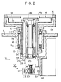
- Fig. 2 illustrates a first embodiment of a grinding wheel support mechanism in an inner diameter saw slicing machine with built-in grinder according to the present invention.
- the mechanism includes a support mechanism for a blade 14.
- a grinding wheel 28 is positioned at a top end when ground.
- a housing 11 is secured to a base 1, and a main spindle 12 is rotatably supported by bearings 11a and 11a, which are mounted in the housing 11.
- a tension head 13 is secured to the top of the main spindle 12.
- a blade 14 is tensioned by a top ring 15, and is attached to the tension head 13.
- a drive pulley 16 is secured to the bottom end of the main spindle 12, and connects to the spindle of a motor (not shown).
- the blade 14 rotates in a substantially horizontal plane, interlocking with the rotation of the main spindle 12.
- An inner cover 18 is secured to the top end of a column 17 mounted on a bracket 21.
- the bracket 21 is secured to the underside of the base 1.
- a slide block 23 is supported by a linear guide 22, which is attached to the bracket 21, so as to be movable vertically.
- a spindle stock 24 stands on the slide block 23, extending through a hollow portion in the main spindle 12. Bearings 24a and 24a are built in the spindle stock 24, and a wheel spindle 26 is rotatably supported by the spindle stock 24. A grinding wheel 28 is secured to a top end of spindle 26.
- a stator 25 is provided in the spindle cradle 24, and a rotor 27 is provided in the wheel spindle 26.
- the stator 25 and the rotor 27 compose a built-in motor.
- a straight drive means 30 is provided below the slide block 23.
- a housing 31 is provided with a worm wheel 32 and a worm 33 for driving the worm wheel 32.
- a screw is formed at a spindle center of the worm wheel 32, and is engaged with a feed screw 34, which is secured to the bottom of the slide block 23.
- the support mechanism for the grinding wheel 28 in the first embodiment is constructed in the described manner.
- the grinding wheel 28 is rotated by the built-in motor, which is composed of the stator 25 and the rotor 27.
- the worm 33 is rotated by a motor (not shown) in the straight drive means 30, so that the worm wheel 32 rotates and the feed screw 34 moves vertically, whereby the whole spindle stock 24 including the rotation mechanism moves vertically.
- Fig. 3 illustrates a second embodiment of a grinding wheel support mechanism.
- the support mechanism for the blade 14 is the same as that of the first embodiment.
- the grinding wheel 28 is positioned at the top end when ground.
- a bracket 41 is secured to the underside of the base 1.
- a spindle stock 42 is attached to the bracket 41, extending through a hollow portion in the main spindle 12.
- Bearings 42a and 42a are mounted in the spindle stock 42, and an intermediate spindle 43 is rotatably supported by the spindle stock 42.
- a drive pulley 45 is secured to the bottom of the intermediate spindle 43, and connects to a spindle of a motor (not shown).
- Spline stocks 43a and 43a are provided in the intermediate spindle 43, and the wheel spindle 44 is supported by the spline stocks 43a and 43a so as to be movable in the direction of the main spindle 12.
- a spline 44a is formed at the outer diameter of the wheel spindle 44.
- the grinding wheel 28 is secured to the top end of the wheel spindle 44.
- a slide block 48 is supported by a linear guide 47, which is attached to a bottom of the bracket 41, so as to be to movable vertically.
- Thrust bearings 48a and 48a are mounted in the slide block 48.
- the top and bottom of a flange 44b, which is formed at the bottom end of the wheel spindle 44, are supported by the thrust bearings 48a and 48a.
- Straight drive means 30, which was explained in the first embodiment, is provided below the slide block 48, the feed screw 34 of the straight drive means 30 being secured to the bottom of the slide block 48.
- the support mechanism for the grinding wheel 28 is constructed in the above described manner.
- the slide block is moved up and down by the straight drive means 30, so that the wheel spindle 44 moves vertically.
- the vertical movement mechanism and the rotation mechanism are independent of each other.
- rotation mechanism and the vertical movement mechanism of the grinding wheel 28 are not limited to the above-described embodiments, and the present invention can be applied in other ways.
- the motor 25, 27 is located between the spindle stock 24 and the wheel spindle 26.
- the motor may be provided outside, as in the second embodiment. Further, in the second embodiment the motor may be located between the spindle stock 42 and the spindle 43.
- the rotational center of the grinding wheel 28 is displaced to the slicing side in the slice feed direction, with respect to the rotational center of the inner diameter saw 14a.
- the grinding wheel 28 can be located close to the inner diameter saw 14a, so that the slicing movement distance Ea of the ingot W can be shorter.
- the diameter Da of the grinding wheel 28 is small, so that its support mechanism can be small and therefore can be low-priced, and the accuracy of the grinding face 28a can be improved.
- the total area of the gap between the inner diameter saw 14a and the grinding wheel 28 (the difference between the area of the circle defined by the inner diameter saw 14a and the area of the grinding wheel 28) is large. As a result, there is less likelihood that the saw 14 will move in the spindle direction due to the wind pressure, etc. caused by the rotation of the grinding wheel 28.
- the present embodiments can provide a low-priced inner diameter saw slicing machine with built-in grinder, wherein the slicing time is short and the accuracy of the grinding face is satisfactory.
Abstract

Description
- The present invention relates to an inner diameter saw slicing machine with built-in grinder.
- Such a machine is used to manufacture a wafer of a predetermined thickness by moving an ingot, such as one made of silicon which is a material for a semiconductor element, relative to a rotary inner diameter saw blade.
- In such a machine, the blade rigidity in the axial direction is low, so slice resistance increases due to kerf wear, and sludge occurs between the ingot and the blade as slicing proceeds. Therefore, the blade kerf is easily displaced from its original position, and as a result both sides of the sliced wafer may be bowed in many cases.
- In manufacturing semiconductor elements, a high plane accuracy is required for the wafer. Therefore lapping and other steps are performed on both sides of the wafer in after-processing. However, the wafer is thin, so it takes much time to carry out the lapping, etc. if both sides of the wafer are bowed.
- In order to alleviate the above-mentioned problems, our Japanese Patent Publication No. 2-12729 (Wafer Manufacturing Method) discloses a slicing machine incorporating a grinding wheel, which machine slices an ingot while simultaneously grinding an ingot cutting face. We have also disclosed a support mechanism for such a grinding wheel in our Japanese Patent Applications Laid-open Nos. 1-210313 and 4-71688.
- Inner diameter saw slicing machines with built-in grinders are classified into vertical and horizontal ones, according to how the ingot is attached. Fig. 5 shows an example of a known vertical inner diameter saw grinding machine with built-in grinder. In this machine a table 4 is supported by a
table guide 2, which is provided on a top of a base 1, in such a manner as to move freely in directions a and b. Acolumn 5 is attached to the table 4. A work holder 7, which is supported by a vertical guide in thecolumn 5 in such a manner as to move freely in a direction Z, is driven by a drive mechanism which is built into thecolumn 5. - In the
manufacturing part 10 next to thetable guide 2, atension head 13 is supported by a rotation mechanism. Ablade 14 is tensioned by atop ring 15 and is attached to thetension head 13. An inner diameter saw 14a is formed at the inner diameter of theblade 14. - Furthermore, a hollow portion is formed in the main spindle which rotatably supports the
blade 14. Agrinding wheel 28 is secured to a wheel spindle, which extends through the hollow portion, in such a manner to move vertically and to rotate. A cup-shaped wheel face 28a is formed on the top of the grindingwheel 28. The grindingwheel 28a is positioned down from the inner diameter saw 14a by the intended thickness of the wafer. The support mechanism for thegrinding wheel 28 in this example is disclosed in aforementioned Japanese Patent Applications Laid-open Nos. 1-210313 and 4-71688. - An
inner cover 18 is fixed at the base 1 in thetension head 13. - In operation of this machine the
blade 14 is rotated at a high speed. An ingot W is moved by the table 4 in a direction Xa from a substantially central position of theblade 14, with a cutting face of the ingot W positioned down from the inner diameter saw 14a by the intended thickness of the wafer, so that the ingot is sliced. The ingot is ground by thewheel face 28a of the grindingwheel 28 prior to being sliced by the inner diameter saw 14a. That is, the ingot is sliced while the end face of the ingot is being ground. - As a result, a wafer which has a fine plane at the end face thereof can be obtained. If the plane accuracy of one side is satisfactory, the time required for an after-process such as lapping can be reduced substantially.
- When the sliced wafers are collected, the
grinding wheel 28 moves in a downward direction so as not to interfere with a wafer collection saucer, which holds the wafer in a collection mechanism. - The rotational center of the
grinding wheel 28 corresponds to that of the inner diameter saw 14a. The relationship between the diameter of the inner diameter saw 14a, the diameter of thegrinding wheel 28, and the initial position of the ingot W is determined in the following manner. - Referring to Fig. 4, in which Fig. 4(a) is a plan view and Fig. 4(b) is a section view, first, the diameter C of the inner diameter saw 14a for the collection saucer and its support spindle to pass through is determined by the diameter A of the ingot W and the length B in Fig. 4(a) in the direction of a slice base, so that a wafer which has been sliced can be collected.
- Next, a gap δ between the
saw 14a and thewheel face 28a in the radial direction is set, so that a diameter Db (=C-2δ) of thegrinding wheel 28 can be determined. - Furthermore, a value γ, which is larger than a width t in the radial direction of the
grinding wheel 28 and thewheel face 28a, is set. Then, the initial position of the ingot W is determined so that a slicing start point Wa can be positioned inwardly from an outer diameter face of the grindingwheel 28 by distance γ. - As a result, a slicing movement distance Eb of the ingot W is calculated by the following equation:

- In this equation, γ is almost automatically set by the width t in the radial direction of the
wheel face 28a of thegrinding wheel 28. So, the slicing movement distance Eb is determined by the gap δ in the radial direction between the inner diameter saw 14a and thegrinding wheel 28. - In this known mechanism, however, the rotational center of the
grinding wheel 28 corresponds to that of the inner diameter saw 14a. This is why the diameter Db of the grindingwheel 28 should be made large in order to reduce the gap δ in the radial direction between the inner diameter saw 14a and the grindingwheel 28. - However, if the diameter Db of the grinding
wheel 28 is made larger, the apparatus for rotating the grinding wheel at a high speed becomes more expensive. If the rotational speed of the grinding wheel is made low so as to avoid such use of the expensive apparatus, it is difficult to obtain a satisfactory grinding face. Further, if the diameter Db of the grinding wheel is made large, it is difficult for thewheel face 28a to be accurate. - Moreover, if the gap δ between the inner diameter saw 14a and the
grinding wheel 28 in the radial direction is small, there is a problem in that the inner diameter saw 14a easily moves in the spindle direction due to the wind pressure caused by the rotation of thegrinding wheel 28. - According to the present invention there is provided an inner diameter saw slicing machine with built-in grinder, comprising:
- a circular blade having an edge formed at an inner diameter thereof and rotatable for slicing an ingot into thin sheets; and
- a grinding wheel disposed within the blade, with its rotational center displaced in the slice feed direction of the ingot with respect to the rotational center of the blade, the grinding wheel being rotatable for grinding the face of the ingot.
- Referring now to a rotation support mechanism for the grinding wheel, in a first form of the invention a spindle stock extends through a hollow portion in a main spindle which supports the said blade for rotation, so as to be movable parallel to the axis of the main spindle. A grinding wheel spindle is rotatably supported by the said spindle stock.
- In a second form of the invention a fixed spindle stock extends through a hollow portion of the main blade spindle. An intermediate spindle is rotatably supported by the spindle stock. A grinding wheel spindle is provided within the intermediate spindle, movable axially thereof. In this case, the wheel spindle and the intermediate spindle can be driven in rotation by an outside motor. However, a built-in motor may be provided by, in the first form, using the wheel spindle as a rotor and the spindle stock as a stator, or in the second form using the intermediate spindle as a rotor and the spindle stock as a stator.
- As already mentioned, the rotational center of the grinding wheel is displaced in the slice feed direction with respect to the rotational center of the inner diameter saw. Therefore, the opening between the inner diameter saw and the grinding wheel in that direction can be made smaller, even if the diameter of the grinding wheel is not large. As a result, the slicing movement distance of the ingot can be shorter.
- Some embodiments of the invention will now be described by way of example and with reference to the accompanying drawings, in which:-
- Fig. 1(a) is a view illustrating an inner diameter saw slicing machine with built-in grinder according to the present invention, and Fig. 1(b) is a section view along line P-P in Fig. 1(a);
- Fig. 2 is a section view illustrating a first embodiment of a grinding wheel support mechanism in a machine according to the present invention;
- Fig. 3 is a section view illustrating a second embodiment of a grinding wheel support mechanism;
- Fig. 4(a) is a view illustrating a known inner diameter saw slicing machine with built-in grinder, and Fig. 4(b) is a section view along line Q-Q in Fig. 4(a); and
- Fig. 5 is an elevation illustrating relevant parts of a known vertical inner diameter saw slicing machine with built-in grinder.
- Fig. 2 illustrates a first embodiment of a grinding wheel support mechanism in an inner diameter saw slicing machine with built-in grinder according to the present invention. The mechanism includes a support mechanism for a
blade 14. A grindingwheel 28 is positioned at a top end when ground. - In Fig. 2, similarly to the prior art machine of Fig. 5, a housing 11 is secured to a base 1, and a
main spindle 12 is rotatably supported bybearings tension head 13 is secured to the top of themain spindle 12. Ablade 14 is tensioned by atop ring 15, and is attached to thetension head 13. Adrive pulley 16 is secured to the bottom end of themain spindle 12, and connects to the spindle of a motor (not shown). Thus, theblade 14 rotates in a substantially horizontal plane, interlocking with the rotation of themain spindle 12. - An
inner cover 18 is secured to the top end of acolumn 17 mounted on abracket 21. Thebracket 21 is secured to the underside of the base 1. Aslide block 23 is supported by alinear guide 22, which is attached to thebracket 21, so as to be movable vertically. - A
spindle stock 24 stands on theslide block 23, extending through a hollow portion in themain spindle 12.Bearings spindle stock 24, and awheel spindle 26 is rotatably supported by thespindle stock 24. A grindingwheel 28 is secured to a top end ofspindle 26. - A
stator 25 is provided in thespindle cradle 24, and arotor 27 is provided in thewheel spindle 26. Thestator 25 and therotor 27 compose a built-in motor. A straight drive means 30 is provided below theslide block 23. - In the straight drive means 30, a
housing 31 is provided with aworm wheel 32 and aworm 33 for driving theworm wheel 32. A screw is formed at a spindle center of theworm wheel 32, and is engaged with afeed screw 34, which is secured to the bottom of theslide block 23. - The support mechanism for the
grinding wheel 28 in the first embodiment is constructed in the described manner. The grindingwheel 28 is rotated by the built-in motor, which is composed of thestator 25 and therotor 27. Moreover, theworm 33 is rotated by a motor (not shown) in the straight drive means 30, so that theworm wheel 32 rotates and thefeed screw 34 moves vertically, whereby thewhole spindle stock 24 including the rotation mechanism moves vertically. - Fig. 3 illustrates a second embodiment of a grinding wheel support mechanism. In this embodiment the support mechanism for the
blade 14 is the same as that of the first embodiment. The grindingwheel 28 is positioned at the top end when ground. - In Fig. 3, a
bracket 41 is secured to the underside of the base 1. Aspindle stock 42 is attached to thebracket 41, extending through a hollow portion in themain spindle 12.Bearings spindle stock 42, and anintermediate spindle 43 is rotatably supported by thespindle stock 42. Adrive pulley 45 is secured to the bottom of theintermediate spindle 43, and connects to a spindle of a motor (not shown). -
Spline stocks intermediate spindle 43, and thewheel spindle 44 is supported by thespline stocks main spindle 12. Aspline 44a is formed at the outer diameter of thewheel spindle 44. The grindingwheel 28 is secured to the top end of thewheel spindle 44. - A
slide block 48 is supported by alinear guide 47, which is attached to a bottom of thebracket 41, so as to be to movable vertically.Thrust bearings slide block 48. The top and bottom of aflange 44b, which is formed at the bottom end of thewheel spindle 44, are supported by thethrust bearings slide block 48, thefeed screw 34 of the straight drive means 30 being secured to the bottom of theslide block 48. - The support mechanism for the
grinding wheel 28 is constructed in the above described manner. The slide block is moved up and down by the straight drive means 30, so that thewheel spindle 44 moves vertically. - When the
middle spindle 43 is rotated by thedrive pulley 45, thewheel spindle 44 is rotated via thespline stocks - It will be noted that in the second embodiment, the vertical movement mechanism and the rotation mechanism are independent of each other.
- It should be understood that the rotation mechanism and the vertical movement mechanism of the
grinding wheel 28 are not limited to the above-described embodiments, and the present invention can be applied in other ways. - For example, in the first embodiment, the
motor spindle stock 24 and thewheel spindle 26. However, the motor may be provided outside, as in the second embodiment. Further, in the second embodiment the motor may be located between thespindle stock 42 and thespindle 43. - In both embodiments, the rotational center of the
grinding wheel 28 is displaced to the slicing side in the slice feed direction, with respect to the rotational center of the inner diameter saw 14a. - Thus, using a
grinding wheel 28 whose diameter Da is slightly larger than the diameter A of the ingot W, the grindingwheel 28 can be located close to the inner diameter saw 14a, so that the slicing movement distance Ea of the ingot W can be shorter. - A comparison between a machine according to the present invention and a known one will now be made by means of specific numerical values.
- First, the common conditions are set as follows:
- The diameter A of an ingot W = 200
- The length B in the slice base direction of the ingot W = 210
- The diameter C of the inner diameter saw 14a = 310 The gap γ in the Xa direction between the ingot and the grinding wheel = 5
- Then, in the case of the known machine:
- When the gap 6 in the radial direction between the inner diameter saw 14a and the
grinding wheel 28 = 20; - The diameter Db of the
grinding wheel 28 = 310 - 2 X 20 = 270 - The slicing movement distance Eb of the ingot W = 210 + 20 + 5 = 235
- On the other hand, in the case of the embodiment of the present invention:
- When the diameter Da of the
grinding wheel 28 = 220; - the gap a in the Xa direction between the grinding wheel with regard to the inner diameter saw = 5;
- The slicing movement distance Ea of ingot W = 210 + 5 + 5 = 220
- As a result,
- the difference (Db - Da) in the diameter of the
grinding wheel 28 = 270 - 220 = 50 - the difference (Eb - Ea) in the slicing movement distance of the ingot W = 235 - 220 = 15
- Moreover, the diameter Da of the
grinding wheel 28 is small, so that its support mechanism can be small and therefore can be low-priced, and the accuracy of the grindingface 28a can be improved. - Furthermore, the total area of the gap between the inner diameter saw 14a and the grinding wheel 28 (the difference between the area of the circle defined by the inner diameter saw 14a and the area of the grinding wheel 28) is large. As a result, there is less likelihood that the
saw 14 will move in the spindle direction due to the wind pressure, etc. caused by the rotation of thegrinding wheel 28. - Therefore, because the diameter of the grinding wheel is smaller and the slicing movement distance of the ingot is shorter, the present embodiments can provide a low-priced inner diameter saw slicing machine with built-in grinder, wherein the slicing time is short and the accuracy of the grinding face is satisfactory.
Claims (7)
- An inner diameter saw slicing machine with built-in grinder, comprising:a circular blade (14) having an edge (14a) formed at an inner diameter thereof and rotatable for slicing an ingot (W) into thin sheets; anda grinding wheel (28) disposed within the blade (14), with its rotational center displaced in the slice feed direction of the ingot with respect to the rotational center of the blade, the grinding wheel being rotatable for grinding the face of the ingot.
- A machine according to claim 1, wherein a rotation support mechanism of the said grinding wheel (28) comprises:a spindle stock (24) axially movable through a hollow portion in a main spindle (12) which rotatably supports the said blade (14) ;a grinding wheel spindle (26) rotatably supported by the said spindle stock;a built-in motor (25,27) whereof the wheel spindle (26) is the rotor and the spindle stock (24) is the stator; andstraight drive means (30) for moving the spindle stock axially, parallel to the axis of the said main spindle.
- A machine according to claim 2, wherein the said straight drive means comprises:a guide member (22, 23) for guiding the said spindle stock (24) in the axial direction of the said main spindle (12) ; anda feed screw mechanism (30) for moving the spindle stock (24) in said axial direction.
- A machine according to claim 1, wherein a rotation support mechanism of the said grinding wheel (28) comprises:a spindle stock (42) extending through a hollow portion in a main spindle (12) which rotatably supports the said blade (14);an inner spindle (43) rotatably supported by the said spindle stock;a grinding wheel spindle (44) coaxial with the said inner spindle and movable parallel to the axis of the said main spindle;rotation drive means for driving the said inner spindle; andstraight drive means (30) for driving the said wheel spindle (44) parallel to the axis of the main spindle.
- A machine according to claim 4, wherein the said grinding wheel spindle (44) is interlocked with the said inner spindle (43) to rotate therewith.
- A machine according to claim 5, wherein the said grinding wheel spindle (44) is splined to the said inner spindle (43) so as to be movable axially relative thereto.
- A machine according to any of claims 4 to 6, wherein the said straight drive means comprises:a guide member (47,48) for guiding the said grinding wheel spindle (44) in the axial direction of the main spindle (12); anda feed screw mechanism (30) for moving the grinding wheel spindle (44) in said axial direction.
Applications Claiming Priority (3)
| Application Number | Priority Date | Filing Date | Title |
|---|---|---|---|
| JP18671195 | 1995-06-30 | ||
| JP186711/95 | 1995-06-30 | ||
| JP18671195A JP3174484B2 (en) | 1995-06-30 | 1995-06-30 | Surface grinding inner peripheral blade cutting compound machine |
Publications (2)
| Publication Number | Publication Date |
|---|---|
| EP0750972A1 true EP0750972A1 (en) | 1997-01-02 |
| EP0750972B1 EP0750972B1 (en) | 2001-09-26 |
Family
ID=16193309
Family Applications (1)
| Application Number | Title | Priority Date | Filing Date |
|---|---|---|---|
| EP96304738A Expired - Lifetime EP0750972B1 (en) | 1995-06-30 | 1996-06-27 | Ingot slicing machine with built-in grinder |
Country Status (5)
| Country | Link |
|---|---|
| US (1) | US5836808A (en) |
| EP (1) | EP0750972B1 (en) |
| JP (1) | JP3174484B2 (en) |
| KR (1) | KR100385428B1 (en) |
| DE (1) | DE69615463T2 (en) |
Cited By (1)
| Publication number | Priority date | Publication date | Assignee | Title |
|---|---|---|---|---|
| CN102364295A (en) * | 2011-06-30 | 2012-02-29 | 常州天合光能有限公司 | Method for measuring thickness of side piece of crystal ingot |
Families Citing this family (2)
| Publication number | Priority date | Publication date | Assignee | Title |
|---|---|---|---|---|
| US9527147B2 (en) | 2014-05-30 | 2016-12-27 | Simonds International Llc | Saw blade indexing assembly |
| CN107962488A (en) * | 2016-10-19 | 2018-04-27 | 张云清 | Store up dirt fire prevention remote control semi auto cutting machine |
Citations (6)
| Publication number | Priority date | Publication date | Assignee | Title |
|---|---|---|---|---|
| FR2469259A1 (en) * | 1979-08-08 | 1981-05-22 | Radiotechnique Compelec | Silicone waver prodn. system - combines cutting and grinding stages into single operation |
| JPS61106207A (en) * | 1984-10-31 | 1986-05-24 | 株式会社東京精密 | Manufacture of wafer |
| EP0313714A1 (en) * | 1987-10-29 | 1989-05-03 | Tokyo Seimitsu Co.,Ltd. | Apparatus and method for slicing a wafer |
| JPH01115604A (en) * | 1987-10-29 | 1989-05-08 | Tokyo Seimitsu Co Ltd | Device of cutting wafer |
| JPH01210313A (en) * | 1988-02-18 | 1989-08-23 | Tokyo Seimitsu Co Ltd | Slicing device for wafer |
| JPH0615634A (en) * | 1992-07-02 | 1994-01-25 | Tokyo Seimitsu Co Ltd | Slicing method of wafer |
Family Cites Families (2)
| Publication number | Priority date | Publication date | Assignee | Title |
|---|---|---|---|---|
| JPH02212729A (en) * | 1989-02-13 | 1990-08-23 | Koorin Denshi Kk | Pressure sensor |
| JP2577653B2 (en) * | 1990-07-10 | 1997-02-05 | フジクリーン工業株式会社 | Adjustment device of discharge flow rate in small-scale merger treatment septic tank |
-
1995
- 1995-06-30 JP JP18671195A patent/JP3174484B2/en not_active Expired - Fee Related
-
1996
- 1996-06-20 KR KR1019960022604A patent/KR100385428B1/en not_active IP Right Cessation
- 1996-06-21 US US08/667,791 patent/US5836808A/en not_active Expired - Fee Related
- 1996-06-27 DE DE69615463T patent/DE69615463T2/en not_active Expired - Fee Related
- 1996-06-27 EP EP96304738A patent/EP0750972B1/en not_active Expired - Lifetime
Patent Citations (8)
| Publication number | Priority date | Publication date | Assignee | Title |
|---|---|---|---|---|
| FR2469259A1 (en) * | 1979-08-08 | 1981-05-22 | Radiotechnique Compelec | Silicone waver prodn. system - combines cutting and grinding stages into single operation |
| JPS61106207A (en) * | 1984-10-31 | 1986-05-24 | 株式会社東京精密 | Manufacture of wafer |
| JPH0212729B2 (en) * | 1984-10-31 | 1990-03-26 | Tokyo Seimitsu Co Ltd | |
| EP0313714A1 (en) * | 1987-10-29 | 1989-05-03 | Tokyo Seimitsu Co.,Ltd. | Apparatus and method for slicing a wafer |
| JPH01115604A (en) * | 1987-10-29 | 1989-05-08 | Tokyo Seimitsu Co Ltd | Device of cutting wafer |
| JPH0471688B2 (en) * | 1987-10-29 | 1992-11-16 | Tokyo Seimitsu Co Ltd | |
| JPH01210313A (en) * | 1988-02-18 | 1989-08-23 | Tokyo Seimitsu Co Ltd | Slicing device for wafer |
| JPH0615634A (en) * | 1992-07-02 | 1994-01-25 | Tokyo Seimitsu Co Ltd | Slicing method of wafer |
Non-Patent Citations (1)
| Title |
|---|
| PATENT ABSTRACTS OF JAPAN vol. 18, no. 217 (M - 1594) 19 April 1994 (1994-04-19) * |
Cited By (2)
| Publication number | Priority date | Publication date | Assignee | Title |
|---|---|---|---|---|
| CN102364295A (en) * | 2011-06-30 | 2012-02-29 | 常州天合光能有限公司 | Method for measuring thickness of side piece of crystal ingot |
| CN102364295B (en) * | 2011-06-30 | 2013-03-06 | 常州天合光能有限公司 | Method for measuring thickness of side piece of crystal ingot |
Also Published As
| Publication number | Publication date |
|---|---|
| DE69615463T2 (en) | 2002-04-25 |
| KR100385428B1 (en) | 2003-08-19 |
| JPH0911227A (en) | 1997-01-14 |
| EP0750972B1 (en) | 2001-09-26 |
| US5836808A (en) | 1998-11-17 |
| JP3174484B2 (en) | 2001-06-11 |
| DE69615463D1 (en) | 2001-10-31 |
| KR970000449A (en) | 1997-01-21 |
Similar Documents
| Publication | Publication Date | Title |
|---|---|---|
| EP0313714B1 (en) | Apparatus and method for slicing a wafer | |
| RU2320467C2 (en) | Method for grinding revolution-symmetry machine part with lengthwise opening and apparatus for performing the same | |
| EP0491051A1 (en) | Numerically controlled grinding machine for glass plate | |
| EP1193029B1 (en) | Double side grinding process for thin disklike work | |
| KR20060044312A (en) | Bevel gear cutting machine for chamfering and/or deburring edges on the teeth of a bevel gear | |
| EP0178843A2 (en) | Surface grinding machine | |
| EP0750972B1 (en) | Ingot slicing machine with built-in grinder | |
| JPH07285024A (en) | Method and device for manufacturing gear | |
| JP5441057B2 (en) | Wire saw | |
| JPS5850822B2 (en) | A method of polishing a knife and a polishing machine for carrying out the method | |
| US3025738A (en) | Cutting apparatus | |
| JP2011110643A5 (en) | ||
| US20030056628A1 (en) | Coaxial spindle cutting saw | |
| GB2289982A (en) | Apparatus and method for manufacturing chamfered semiconductor wafers | |
| JPH1076515A (en) | Cutting method of hard material such as stone and cutting device | |
| US4712535A (en) | Method and apparatus for severing wafers | |
| US6375555B1 (en) | Vane groove grinding apparatus for compressor cylinder | |
| JP2737783B2 (en) | Wafer cutting equipment | |
| JP3199355B2 (en) | Dressing method of inner peripheral blade | |
| JP2020075314A (en) | Beveling device for wafer | |
| CN220196535U (en) | Automatic gear milling machine | |
| JP2537458B2 (en) | Chip refiner by dual contouring | |
| JP2681582B2 (en) | Sheet material slitting method and slitter device | |
| CN116748604A (en) | Automatic gear milling machine | |
| JP2001025943A (en) | Outer-periphery surface grinding machine and grinding method for cylindrical work |
Legal Events
| Date | Code | Title | Description |
|---|---|---|---|
| PUAI | Public reference made under article 153(3) epc to a published international application that has entered the european phase |
Free format text: ORIGINAL CODE: 0009012 |
|
| AK | Designated contracting states |
Kind code of ref document: A1 Designated state(s): DE GB IT |
|
| 17P | Request for examination filed |
Effective date: 19970207 |
|
| 17Q | First examination report despatched |
Effective date: 19991118 |
|
| GRAG | Despatch of communication of intention to grant |
Free format text: ORIGINAL CODE: EPIDOS AGRA |
|
| GRAG | Despatch of communication of intention to grant |
Free format text: ORIGINAL CODE: EPIDOS AGRA |
|
| GRAH | Despatch of communication of intention to grant a patent |
Free format text: ORIGINAL CODE: EPIDOS IGRA |
|
| GRAH | Despatch of communication of intention to grant a patent |
Free format text: ORIGINAL CODE: EPIDOS IGRA |
|
| GRAA | (expected) grant |
Free format text: ORIGINAL CODE: 0009210 |
|
| AK | Designated contracting states |
Kind code of ref document: B1 Designated state(s): DE GB IT |
|
| REF | Corresponds to: |
Ref document number: 69615463 Country of ref document: DE Date of ref document: 20011031 |
|
| REG | Reference to a national code |
Ref country code: GB Ref legal event code: IF02 |
|
| PLBE | No opposition filed within time limit |
Free format text: ORIGINAL CODE: 0009261 |
|
| STAA | Information on the status of an ep patent application or granted ep patent |
Free format text: STATUS: NO OPPOSITION FILED WITHIN TIME LIMIT |
|
| 26N | No opposition filed | ||
| PGFP | Annual fee paid to national office [announced via postgrant information from national office to epo] |
Ref country code: GB Payment date: 20030624 Year of fee payment: 8 |
|
| PGFP | Annual fee paid to national office [announced via postgrant information from national office to epo] |
Ref country code: DE Payment date: 20030626 Year of fee payment: 8 |
|
| PG25 | Lapsed in a contracting state [announced via postgrant information from national office to epo] |
Ref country code: GB Free format text: LAPSE BECAUSE OF NON-PAYMENT OF DUE FEES Effective date: 20040627 |
|
| PG25 | Lapsed in a contracting state [announced via postgrant information from national office to epo] |
Ref country code: DE Free format text: LAPSE BECAUSE OF NON-PAYMENT OF DUE FEES Effective date: 20050101 |
|
| GBPC | Gb: european patent ceased through non-payment of renewal fee |
Effective date: 20040627 |
|
| PG25 | Lapsed in a contracting state [announced via postgrant information from national office to epo] |
Ref country code: IT Free format text: LAPSE BECAUSE OF NON-PAYMENT OF DUE FEES Effective date: 20050627 |