EP0750590B1 - Waste treatment plant and process - Google Patents
Waste treatment plant and process Download PDFInfo
- Publication number
- EP0750590B1 EP0750590B1 EP95912952A EP95912952A EP0750590B1 EP 0750590 B1 EP0750590 B1 EP 0750590B1 EP 95912952 A EP95912952 A EP 95912952A EP 95912952 A EP95912952 A EP 95912952A EP 0750590 B1 EP0750590 B1 EP 0750590B1
- Authority
- EP
- European Patent Office
- Prior art keywords
- waste treatment
- bioreactor
- waste
- waste material
- conduit
- Prior art date
- Legal status (The legal status is an assumption and is not a legal conclusion. Google has not performed a legal analysis and makes no representation as to the accuracy of the status listed.)
- Expired - Lifetime
Links
- 239000002699 waste material Substances 0.000 title claims abstract description 102
- 238000000034 method Methods 0.000 title claims abstract description 29
- 239000000725 suspension Substances 0.000 claims abstract description 6
- 230000020477 pH reduction Effects 0.000 claims description 30
- 239000007789 gas Substances 0.000 claims description 25
- 239000000463 material Substances 0.000 claims description 23
- CURLTUGMZLYLDI-UHFFFAOYSA-N Carbon dioxide Chemical compound O=C=O CURLTUGMZLYLDI-UHFFFAOYSA-N 0.000 claims description 18
- 235000014113 dietary fatty acids Nutrition 0.000 claims description 14
- 229930195729 fatty acid Natural products 0.000 claims description 14
- 239000000194 fatty acid Substances 0.000 claims description 14
- 150000004665 fatty acids Chemical class 0.000 claims description 14
- 239000007788 liquid Substances 0.000 claims description 13
- 238000012546 transfer Methods 0.000 claims description 11
- 239000001569 carbon dioxide Substances 0.000 claims description 9
- 229910002092 carbon dioxide Inorganic materials 0.000 claims description 9
- 244000052616 bacterial pathogen Species 0.000 claims description 8
- QGZKDVFQNNGYKY-UHFFFAOYSA-N Ammonia Chemical compound N QGZKDVFQNNGYKY-UHFFFAOYSA-N 0.000 claims description 6
- IJGRMHOSHXDMSA-UHFFFAOYSA-N Atomic nitrogen Chemical compound N#N IJGRMHOSHXDMSA-UHFFFAOYSA-N 0.000 claims description 6
- 238000010438 heat treatment Methods 0.000 claims description 5
- OKTJSMMVPCPJKN-UHFFFAOYSA-N Carbon Chemical compound [C] OKTJSMMVPCPJKN-UHFFFAOYSA-N 0.000 claims description 4
- 229910052799 carbon Inorganic materials 0.000 claims description 4
- 230000008030 elimination Effects 0.000 claims description 4
- 238000003379 elimination reaction Methods 0.000 claims description 4
- 240000004808 Saccharomyces cerevisiae Species 0.000 claims description 3
- 238000013019 agitation Methods 0.000 claims description 3
- 229910021529 ammonia Inorganic materials 0.000 claims description 3
- 229910052757 nitrogen Inorganic materials 0.000 claims description 3
- 239000002002 slurry Substances 0.000 claims description 3
- 238000004891 communication Methods 0.000 claims description 2
- 230000003247 decreasing effect Effects 0.000 claims description 2
- BHEPBYXIRTUNPN-UHFFFAOYSA-N hydridophosphorus(.) (triplet) Chemical compound [PH] BHEPBYXIRTUNPN-UHFFFAOYSA-N 0.000 claims description 2
- 238000002347 injection Methods 0.000 claims 2
- 239000007924 injection Substances 0.000 claims 2
- 210000003608 fece Anatomy 0.000 abstract description 8
- 238000001914 filtration Methods 0.000 abstract description 8
- 241001465754 Metazoa Species 0.000 abstract description 5
- 238000000855 fermentation Methods 0.000 description 13
- 239000012530 fluid Substances 0.000 description 12
- QAOWNCQODCNURD-UHFFFAOYSA-N Sulfuric acid Chemical compound OS(O)(=O)=O QAOWNCQODCNURD-UHFFFAOYSA-N 0.000 description 11
- 239000010802 sludge Substances 0.000 description 10
- 239000007787 solid Substances 0.000 description 10
- 230000004151 fermentation Effects 0.000 description 9
- 239000002253 acid Substances 0.000 description 8
- 238000013461 design Methods 0.000 description 8
- QTBSBXVTEAMEQO-UHFFFAOYSA-N Acetic acid Chemical compound CC(O)=O QTBSBXVTEAMEQO-UHFFFAOYSA-N 0.000 description 6
- 239000002198 insoluble material Substances 0.000 description 5
- 239000000047 product Substances 0.000 description 5
- FERIUCNNQQJTOY-UHFFFAOYSA-N Butyric acid Chemical compound CCCC(O)=O FERIUCNNQQJTOY-UHFFFAOYSA-N 0.000 description 4
- 241000196324 Embryophyta Species 0.000 description 4
- 239000010796 biological waste Substances 0.000 description 4
- XBDQKXXYIPTUBI-UHFFFAOYSA-N dimethylselenoniopropionate Natural products CCC(O)=O XBDQKXXYIPTUBI-UHFFFAOYSA-N 0.000 description 4
- FUZZWVXGSFPDMH-UHFFFAOYSA-N hexanoic acid Chemical compound CCCCCC(O)=O FUZZWVXGSFPDMH-UHFFFAOYSA-N 0.000 description 4
- 244000144972 livestock Species 0.000 description 4
- 230000014759 maintenance of location Effects 0.000 description 4
- 244000005700 microbiome Species 0.000 description 4
- NQPDZGIKBAWPEJ-UHFFFAOYSA-N valeric acid Chemical compound CCCCC(O)=O NQPDZGIKBAWPEJ-UHFFFAOYSA-N 0.000 description 4
- PEDCQBHIVMGVHV-UHFFFAOYSA-N Glycerine Chemical compound OCC(O)CO PEDCQBHIVMGVHV-UHFFFAOYSA-N 0.000 description 3
- 238000000429 assembly Methods 0.000 description 3
- MNWFXJYAOYHMED-UHFFFAOYSA-N heptanoic acid Chemical compound CCCCCCC(O)=O MNWFXJYAOYHMED-UHFFFAOYSA-N 0.000 description 3
- 150000007524 organic acids Chemical class 0.000 description 3
- 235000005985 organic acids Nutrition 0.000 description 3
- 102000004169 proteins and genes Human genes 0.000 description 3
- 108090000623 proteins and genes Proteins 0.000 description 3
- 230000000717 retained effect Effects 0.000 description 3
- 239000006228 supernatant Substances 0.000 description 3
- 239000002028 Biomass Substances 0.000 description 2
- 241000283690 Bos taurus Species 0.000 description 2
- 229920002488 Hemicellulose Polymers 0.000 description 2
- 240000005979 Hordeum vulgare Species 0.000 description 2
- 235000007340 Hordeum vulgare Nutrition 0.000 description 2
- 150000007513 acids Chemical class 0.000 description 2
- 150000001720 carbohydrates Chemical class 0.000 description 2
- 235000014633 carbohydrates Nutrition 0.000 description 2
- 238000006243 chemical reaction Methods 0.000 description 2
- 238000010586 diagram Methods 0.000 description 2
- 238000005516 engineering process Methods 0.000 description 2
- 229920005610 lignin Polymers 0.000 description 2
- 238000004519 manufacturing process Methods 0.000 description 2
- WWZKQHOCKIZLMA-UHFFFAOYSA-N octanoic acid Chemical compound CCCCCCCC(O)=O WWZKQHOCKIZLMA-UHFFFAOYSA-N 0.000 description 2
- 230000003647 oxidation Effects 0.000 description 2
- 238000007254 oxidation reaction Methods 0.000 description 2
- 239000002245 particle Substances 0.000 description 2
- 239000007793 ph indicator Substances 0.000 description 2
- WLJVXDMOQOGPHL-UHFFFAOYSA-N phenylacetic acid Chemical compound OC(=O)CC1=CC=CC=C1 WLJVXDMOQOGPHL-UHFFFAOYSA-N 0.000 description 2
- 235000019260 propionic acid Nutrition 0.000 description 2
- 238000005086 pumping Methods 0.000 description 2
- IUVKMZGDUIUOCP-BTNSXGMBSA-N quinbolone Chemical compound O([C@H]1CC[C@H]2[C@H]3[C@@H]([C@]4(C=CC(=O)C=C4CC3)C)CC[C@@]21C)C1=CCCC1 IUVKMZGDUIUOCP-BTNSXGMBSA-N 0.000 description 2
- 238000004064 recycling Methods 0.000 description 2
- 238000001179 sorption measurement Methods 0.000 description 2
- 229940005605 valeric acid Drugs 0.000 description 2
- 239000002351 wastewater Substances 0.000 description 2
- 241000894006 Bacteria Species 0.000 description 1
- 206010016825 Flushing Diseases 0.000 description 1
- 241000233866 Fungi Species 0.000 description 1
- 241000178260 Magnusiomyces ingens Species 0.000 description 1
- 240000004658 Medicago sativa Species 0.000 description 1
- 235000010624 Medicago sativa Nutrition 0.000 description 1
- 229910019142 PO4 Inorganic materials 0.000 description 1
- OAICVXFJPJFONN-UHFFFAOYSA-N Phosphorus Chemical compound [P] OAICVXFJPJFONN-UHFFFAOYSA-N 0.000 description 1
- 229920005830 Polyurethane Foam Polymers 0.000 description 1
- 240000006394 Sorghum bicolor Species 0.000 description 1
- 235000011684 Sorghum saccharatum Nutrition 0.000 description 1
- 230000002053 acidogenic effect Effects 0.000 description 1
- 238000005273 aeration Methods 0.000 description 1
- OBETXYAYXDNJHR-UHFFFAOYSA-N alpha-ethylcaproic acid Natural products CCCCC(CC)C(O)=O OBETXYAYXDNJHR-UHFFFAOYSA-N 0.000 description 1
- 238000004458 analytical method Methods 0.000 description 1
- 125000003118 aryl group Chemical group 0.000 description 1
- 235000015278 beef Nutrition 0.000 description 1
- 230000015572 biosynthetic process Effects 0.000 description 1
- 125000004432 carbon atom Chemical group C* 0.000 description 1
- 230000015556 catabolic process Effects 0.000 description 1
- 230000001413 cellular effect Effects 0.000 description 1
- 239000007795 chemical reaction product Substances 0.000 description 1
- 150000001875 compounds Chemical class 0.000 description 1
- 238000009833 condensation Methods 0.000 description 1
- 230000005494 condensation Effects 0.000 description 1
- 238000010276 construction Methods 0.000 description 1
- 238000007796 conventional method Methods 0.000 description 1
- 238000001816 cooling Methods 0.000 description 1
- 235000013365 dairy product Nutrition 0.000 description 1
- 230000006378 damage Effects 0.000 description 1
- 201000010099 disease Diseases 0.000 description 1
- 208000037265 diseases, disorders, signs and symptoms Diseases 0.000 description 1
- 238000001035 drying Methods 0.000 description 1
- 230000000694 effects Effects 0.000 description 1
- 239000003925 fat Substances 0.000 description 1
- 239000003337 fertilizer Substances 0.000 description 1
- 239000012065 filter cake Substances 0.000 description 1
- 239000000706 filtrate Substances 0.000 description 1
- 238000005189 flocculation Methods 0.000 description 1
- 230000016615 flocculation Effects 0.000 description 1
- 238000011010 flushing procedure Methods 0.000 description 1
- 150000004676 glycans Chemical class 0.000 description 1
- 208000015181 infectious disease Diseases 0.000 description 1
- 235000014655 lactic acid Nutrition 0.000 description 1
- 150000002632 lipids Chemical class 0.000 description 1
- 239000010808 liquid waste Substances 0.000 description 1
- 229920002521 macromolecule Polymers 0.000 description 1
- 238000012423 maintenance Methods 0.000 description 1
- 239000011159 matrix material Substances 0.000 description 1
- 244000000010 microbial pathogen Species 0.000 description 1
- 239000000203 mixture Substances 0.000 description 1
- 125000005473 octanoic acid group Chemical class 0.000 description 1
- 230000000737 periodic effect Effects 0.000 description 1
- 150000002989 phenols Chemical class 0.000 description 1
- 229960003424 phenylacetic acid Drugs 0.000 description 1
- 239000003279 phenylacetic acid Substances 0.000 description 1
- NBIIXXVUZAFLBC-UHFFFAOYSA-K phosphate Chemical compound [O-]P([O-])([O-])=O NBIIXXVUZAFLBC-UHFFFAOYSA-K 0.000 description 1
- 239000010452 phosphate Substances 0.000 description 1
- 229910052698 phosphorus Inorganic materials 0.000 description 1
- 239000011574 phosphorus Substances 0.000 description 1
- 229920000642 polymer Polymers 0.000 description 1
- 229920001282 polysaccharide Polymers 0.000 description 1
- 239000005017 polysaccharide Substances 0.000 description 1
- 239000011496 polyurethane foam Substances 0.000 description 1
- 244000144977 poultry Species 0.000 description 1
- 238000012545 processing Methods 0.000 description 1
- 150000003254 radicals Chemical class 0.000 description 1
- 230000003014 reinforcing effect Effects 0.000 description 1
- 239000000523 sample Substances 0.000 description 1
- 239000004576 sand Substances 0.000 description 1
- 235000011044 succinic acid Nutrition 0.000 description 1
- 150000003444 succinic acids Chemical class 0.000 description 1
- 235000000346 sugar Nutrition 0.000 description 1
- 150000008163 sugars Chemical class 0.000 description 1
- 239000001117 sulphuric acid Substances 0.000 description 1
- 235000011149 sulphuric acid Nutrition 0.000 description 1
- 229920002994 synthetic fiber Polymers 0.000 description 1
- 231100000331 toxic Toxicity 0.000 description 1
- 230000002588 toxic effect Effects 0.000 description 1
- 239000003039 volatile agent Substances 0.000 description 1
- XLYOFNOQVPJJNP-UHFFFAOYSA-N water Substances O XLYOFNOQVPJJNP-UHFFFAOYSA-N 0.000 description 1
Images

Classifications
-
- C—CHEMISTRY; METALLURGY
- C02—TREATMENT OF WATER, WASTE WATER, SEWAGE, OR SLUDGE
- C02F—TREATMENT OF WATER, WASTE WATER, SEWAGE, OR SLUDGE
- C02F3/00—Biological treatment of water, waste water, or sewage
- C02F3/28—Anaerobic digestion processes
- C02F3/286—Anaerobic digestion processes including two or more steps
-
- C—CHEMISTRY; METALLURGY
- C02—TREATMENT OF WATER, WASTE WATER, SEWAGE, OR SLUDGE
- C02F—TREATMENT OF WATER, WASTE WATER, SEWAGE, OR SLUDGE
- C02F11/00—Treatment of sludge; Devices therefor
- C02F11/02—Biological treatment
- C02F11/04—Anaerobic treatment; Production of methane by such processes
-
- C—CHEMISTRY; METALLURGY
- C12—BIOCHEMISTRY; BEER; SPIRITS; WINE; VINEGAR; MICROBIOLOGY; ENZYMOLOGY; MUTATION OR GENETIC ENGINEERING
- C12M—APPARATUS FOR ENZYMOLOGY OR MICROBIOLOGY; APPARATUS FOR CULTURING MICROORGANISMS FOR PRODUCING BIOMASS, FOR GROWING CELLS OR FOR OBTAINING FERMENTATION OR METABOLIC PRODUCTS, i.e. BIOREACTORS OR FERMENTERS
- C12M23/00—Constructional details, e.g. recesses, hinges
- C12M23/58—Reaction vessels connected in series or in parallel
Definitions
- THIS INVENTION relates to a waste treatment plant and process.
- Lignocellulose in the animal faeces is derived from barley (e.g. barley awns), lucerne, sorghum and other stockfeeds.
- the conventional methods for disposal of the indigestible material included passing the indigestible material to anaerobic ponds, septic tanks or pits.
- the indigestible material was dewatered by filtration or by drying on open or covered sand beds. The dried sludge was subsequently incinerated or used as fertiliser. In some cases the indigestible material was used as landfill.
- the indigestible material also could not be spread onto anaerobic ponds or used as landfill in Moslem countries such as Malaysia or Indonesia. In countries where this method of disposal could be achieved, it was relatively expensive because of the transportation costs.
- the indigestible material also contained many pathogenic micro-organisms after the anaerobic fermentation step which were not eradicated prior to the pumping of the indigestible material as a slurry into anaerobic ponds or when spread onto land and thus caused disease or infection.
- free volatile fatty acids can eliminate bacterial pathogens.
- EP-A - 0 132 609 describes the treatment of wastewater by an activated sludge process wherein wastewater containing BOD 5 and phosphate values is admixed in an initial zone with biomass-containing recycled sludge to form a mixed liquor under conditions effecting sorption of BOD 5 in the biomass.
- the mixed liquor is subsequently subjected to aeration in an oxidation zone under conditions for effecting oxidation of BOD 5 and settled in a settling zone, thereby forming a supernatant liquor and a dense sludge which is recycled to the BOD sorption zone.
- the process of the invention includes the following steps:
- the waste material which is subject to the process of the invention suitably includes human or animal faeces and preferably faeces from livestock feedlots as described above which may have a stockfeed component containing lignocellulose.
- Each bioreactor may be interconnected by an overflow conduit so that waste material or influent i s quickly and efficiently transferred from one bioreactor to an adjacent bioreactor without the need for pumping material so as to transfer material from one bioreactor to another.
- Each bioreactor is suitably provided with agitation means which keeps the contents of each bioreactor in the form of a slurry or suspension so that the solid particles are maintained in the suspended state to achieve the object of the invention.
- each bioreactor is also suitably subject to appropriate heating means and in one form this may be provided by steam being passed into and out of each bioreactor.
- heating means may be utilised such as electrical heating.
- the temperature in each bioreactor is maintained at a desired temperature by suitably thermostatically controlled means between 25-50°C and more suitably 30-40°C. In a preferred form the temperature is slowly decreased as the waste material passes through each bioreactor from initially 40°C to finally 30°C.
- the pH of the waste material fed into the bioreactors is maintained between 5.0-7.0 and more suitably between 5.8-6.4.
- the retention time in each bioreactor may be 12-48 but more suitably 24 hours.
- the waste effluent After the waste effluent leaves the bioreactor system it may be passed through a filter or sieve to filter out the insoluble material which is preferably incinerated or if it is to be spread onto land it may be passed through acidification tanks as described hereinafter. It will be appreciated that removal of the insoluble material may take place in any suitable manner. While filtration is a preferred procedure, flocculation may also be utilised.
- the supernatant or soluble liquid from the filter may then be passed into the one or more acidification tanks and preferably maintained in said tank(s) for a period of 24-48 hours to reduce the pH to a value of below 4.5 and more suitably between 4.0-4.5 which is below the pKa of the volatile fatty acids e.g. acetic acid, propionic acid, butyric acid, valeric acid, caproic acid, enanthic acid as well as octanoic acid as well as relevant isomers.
- volatile fatty acids e.g. acetic acid, propionic acid, butyric acid, valeric acid, caproic acid, enanthic acid as well as octanoic acid as well as relevant isomers.
- VFAs volatile fatty acids
- the waste effluent after it leaves the bioreactor system may be passed through the acidification tank(s) before removal of the insoluble material.
- the waste effluent may then be passed to a curtain assembly as described hereinafter. This procedure is preferable when it is impossible to incinerate the insoluble material after filtration of the waste material after passage of the waste material through the bioreactor system.
- Such means may, for example, comprise conduit(s) for the carbon dioxide or other gas which extend into the or each acidification tank. Such conduits may be connected to a suitable source of carbon dioxide or said other gas.
- means such as appropriate transfer conduits for transferring effluent gases (which may include carbon dioxide) generated in the bioreactor system to the acidification tank(s) to maintain a gaseous atmosphere above the waste material being acidified.
- effluent gases which may include carbon dioxide
- This feature as stated above is useful in that it inhibits the growth of yeasts or fungi in the acidification tank(s) such as Candida ingens.
- the gases may subsequently be removed from the acidification tank(s) by appropriate conduit(s) to gas scrubbers for eventual discharge.
- the waste from the acidification tank(s) may be passed to a hanging curtain assembly, which maybe, for example, a hanging curtain assembly of the of the type described in Patent Specification 91080/91 whereby nitrogen in the form of ammonia, dissolved phosphorous and carbon as volatile fatty acids may be eliminated from the waste material.
- a hanging curtain assembly of the of the type described in Patent Specification 91080/91 whereby nitrogen in the form of ammonia, dissolved phosphorous and carbon as volatile fatty acids may be eliminated from the waste material.
- Some of the carbon is evolved as carbon dioxide with the remainder being retained by the micro-organisms contained therein.
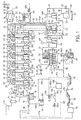
- FIG 1 there is shown an in-ground holding tank 10 for influent comprising faeces admixed with undigested feed or waste feed from a piggery (not shown).
- the influent is pumped by a feed pump 11 through a macerator 12 which grinds the particles in the influent into small pieces or finely divided material before the influent is passed into bioreactor 13 provided with agitator 14 having shaft 15 mounted in bearing 16.
- conduit 17 between holding tank 10 and macerator 12, conduit 18 between feed pump 11 and macerator 12 and conduit 19 which provides communication between inlet conduit 20 and bioreactor 13.
- Conduit 20 is provided with a shut off valve V 1 and flow control diaphragm valve V 2 .
- Conduit 21 functions as a return line for recycling influent from bioreactor 13 through conduit 20 back to holding tank 10 which depends upon operation of valves V 1 and V 2 .
- bioreactors 13A, 13B, 13C, 13D and 13E all having a similar construction to bioreactor 13.
- overflow conduits 22 between adjacent bioreactors for transfer of fluid.
- Each bioreactor is also provided with a drain line 23 having a shut off valve V 1 .
- each steam conduit 28 which each communicate with supply conduit 26 as shown which pass steam into each of the bioreactors 13-13E as shown.
- Each steam conduit 28 is also provided with a vacuum breaker valve V 3 to stop back siphonage of fluid as shown.
- a shut off valve V 1 in each conduit 28 as well as a further valve V 1 associated with a temperature control valve 29 in the form of a sliding gate valve associated with conduit 30 which also has a thermostat or thermostat controller 31 in the form of a probe which extends into each bioreactor which controls the temperature attained in each bioreactor 13-13E.
- each bioreactor 13-13E which each communicates with conduit 33 for passing effluent gases to gas line 49A described hereinafter. Effluent gases may then pass through a return line 34A from gas line 49A to a pair of gas scrubbers 34 connected in parallel as shown.
- the bottom gas scrubber 34 has an associated conduit 35 and the top gas scrubber 34 has an associated conduit 36.
- Each of conduits 35 and 36 are shut off with valves V 4 and communicate with conduit 37 which communicates with fan 38 and stack 39.
- steam trap 40 There is also provided steam trap 40. Valves V 4 function to take one of scrubbers 34 out of service for maintenance purposes.
- the effluent after it passes out through the final bioreactor 13E is passed through a feed pump 41 through conduit 42 and subsequently through conduit 43 to a sludge filter 44. Pressure indicators 51 are shown associated with conduit 43 as, well as conduit 47.
- a solid fraction 45 from sludge filter 44 is retained in container 46 whereby solid fraction 45 which is mainly lignocellulose may be transferred by truck 46A for incineration or other form of disposal.
- a liquid fraction rich in volatile fatty acids or VFAs is then passed to a VFA feed tank 48 through conduit 47 where it is held for 2 days before being passed through conduit 52 to a transfer pump 53 before being fed into VFA holding tank 50 via conduit 54 which communicates with conduit 55.
- Conduit 28A functions to transfer steam from conduit 26 to a VFA liquid acidification tank 56 which is fed with sulfuric acid (H 2 SO 4 ) from a sulfuric acid feed tank 57 which is associated with an inlet conduit 58 having a pressure relief valve V 5 and a drain conduit 59 which communicates with conduit 62 which passes through a sulfuric acid pump 60. There is also provided a sump 61.
- the sulfuric acid is passed through conduit 62 which communicates with conduits 58 and 59 as shown to acidification tank 56 which is also provided with an agitator 14 as shown.
- Each of agitators 14 and associated shafts 15 in bioreactors 13-13E as well as tank 56 are provided with a variable speed control (VS) shown in phantom. Material may be passed from tank 56 to conduit 52 through conduit 49 which thereafter may be transferred to conduit 55 and hence to tank 50 or alternatively to tank 56 though conduit 57 depending upon operation of shut off valves V 1 .
- VS variable speed control
- conduits 64, 63 and 65 which each communicate with tanks 48, 56 and 50 respectively for transferring effluent gases back into gas line 49A and subsequent flow through return line 34A.
- Conduit 67 is also shown having temperature controller 31 for control of temperature in tank 56. Conduit 67 communicates with conduit 28A as shown via temperature control valve 29.
- Tank 50 is also provided with temperature indicator 68 and tank 56 is also provided with pH indicator 69 as shown.
- Liquid from VFA holding tank 50 is passed to a hanging curtain assembly 70 through conduit 71 and passed through a curtain feed pump 72 provided with a variable speed control VS.
- Conduit 71 may be split into separate conduits 73 and 74, 75 and 76 as well as 77 and 78 which may apply liquid waste as shown to either side of a curtain module or curtain sub-assembly 79A.
- the flow connections of sub-assemblies 79B to pump 72 are omitted for clarity.
- Each of sub-assemblies 79A and 79B are retained in a housing 80 having a sloping drain floor 81.
- a temperature indicator 82 which is associated with housing 80.
- Gases from housing 80 may be passed through conduit 83 through damper valve V 6 , cooling fan 84, and stack 85. There is also shown a further damper V 6 which communicates with the interior of housing 80 and the operation of each damper valve V 6 controls air flow through housing 80.
- Waste effluent may be passed from the sloping floor 81 of housing 80 to a treated waste holding tank 86 having a discharge pump 87 associated therewith via conduit 86A.
- a level element 91 which may control pump 87 for maintaining the level of fluid in housing 80.
- pH indicator 89 There is also provided pH indicator 89. Fluid may be pumped by pump 87 through discharge conduit 88 which has a return line 89A. Waste may be recycled through conduit 90 to housing 80 as shown from conduit 88.
- waste may be passed to a treatment pond 92 which communicates with another pond 93 via conduit 94 with the assistance of pump 95. waste may subsequently be transferred to a feed tank 96 via conduit 97.
- conduit 97A may pass fluid to a treatment channel or flume 98 of a piggery. Subsequently fluid may be passed to holding tank 10 via a bypass plate 99 or alternatively through a conduit 100 to an in ground holding tank 101 having a discharge pump 102 which may transfer fluid to treatment pond 92 through conduit 103.
- conduit 104 material from conduit 88 may be transferred through conduit 104 to a filter 105 whereby a solid fraction 107 may be deposited in container 106 before being removed by truck 108A for incineration or other form of disposal.
- a liquid fraction may be passed from filter 105 via conduit 105A to a liquid tank 108 whereby it may be recycled to flume 98 via conduit 109 and with the assistance of pump 110.
- FIG 2 represents a modified waste treatment plant in contrast to the waste treatment plant shown in FIG 1. Similar reference numerals are utilised for the sake of convenience.
- One difference between the FIG 1 plant and the FIG 2 plant is the adoption of bioreactors 13-13F on a slope as indicated with overflow conduits 22 facilitating transfer of fluid from adjacent bioreactors. Valves are also not indicated for the sake of convenience.
- One conduit 18 interconnects holding tank 10 and bioreactor 13 and steam from boiler 24 flows through conduit 26 and subsequently through inlet conduits 28 to a respective bioreactor 13-13F.
- Exhaust conduits 32 for gas also communicate with main transfer conduit 33 as described above in the FIG 1 waste treatment plant.
- Gas is passed to acidification tanks 56A and 56B through conduit 33 and into each tank through inlet conduits 33A and 33B as shown. There is also supplied a gas return line 34A to gas scrubbers 34.
- the waste effluent or waste material after emerging from the final bioreactor 13F may be transferred directly to acidification tank 56A through conduit 44A shown in phantom.
- the waste material will still have the insoluble component entrained therein so that the waste material may then be transferred from acidification tank 56B to filter 44 after passage through conduit 45A also shown in phantom.
- the liquid fraction may then be transferred to curtain assembly 70 through conduit 46A also shown in phantom.
- VFA liquor acidification tanks 56A and 56B whereby a liquid fraction from sludge filter 44 is passed through conduit 47 and subsequently into tank 56A.
- Sulphuric acid is pumped by pump 60 from a tank or drum 57 via conduit 62 to tank 56A. Material may then be passed from tank 56A to tank 56B through conduit 62A. Acid treated fluid may then be passed to curtain assembly 70 through conduit 71.
- Waste liquid after passing through curtain assembly 70 is passed to filter feed tank 86 through conduit 86A whereafter fluid is pumped by pump 87 to treatment pond 92 by conduit 88 or passed through recycling conduit 90 to curtain assembly 70 after passage through conduit 104A.
- Liquid from pond 92 is passed through conduit 97 back to flume 98 with the agency of pump 95.
- Fluid may also be passed to filter 105 from curtain assembly 70 through conduit 104A whereby a liquid fraction may be passed to treatment tank 108 through conduit 105A whereafter fluid may be passed to conduit 97 through conduit 109 assisted by pump 110.
- VFAs volatile fatty acids
- Non-volatiles such as lactic and/or succinic acids are not produced.
- Traces ( ⁇ -3mML -1 ) of phenylacetic acid do appear. The purpose of restricting the end products of fermentation to VFAs ensures an excess of these acids is present to effect destruction of bacterial pathogens present in the waste.
- the serial fermentation also enables conditions of pH, fermentation and residue time in each bioreactor to be manipulated in order to optimise production of the VFAs.
Landscapes
- Life Sciences & Earth Sciences (AREA)
- Engineering & Computer Science (AREA)
- Chemical & Material Sciences (AREA)
- Organic Chemistry (AREA)
- Health & Medical Sciences (AREA)
- Microbiology (AREA)
- Water Supply & Treatment (AREA)
- Bioinformatics & Cheminformatics (AREA)
- Environmental & Geological Engineering (AREA)
- Hydrology & Water Resources (AREA)
- Wood Science & Technology (AREA)
- Zoology (AREA)
- Sustainable Development (AREA)
- Clinical Laboratory Science (AREA)
- General Health & Medical Sciences (AREA)
- Genetics & Genomics (AREA)
- Biochemistry (AREA)
- Chemical Kinetics & Catalysis (AREA)
- General Chemical & Material Sciences (AREA)
- Oil, Petroleum & Natural Gas (AREA)
- Molecular Biology (AREA)
- Biotechnology (AREA)
- Biomedical Technology (AREA)
- General Engineering & Computer Science (AREA)
- Biodiversity & Conservation Biology (AREA)
- Processing Of Solid Wastes (AREA)
- Treatment Of Sludge (AREA)
- Apparatus Associated With Microorganisms And Enzymes (AREA)
- Fertilizers (AREA)
- Paper (AREA)
- Electrical Discharge Machining, Electrochemical Machining, And Combined Machining (AREA)
- Chemical Treatment Of Metals (AREA)
- Activated Sludge Processes (AREA)
- Purification Treatments By Anaerobic Or Anaerobic And Aerobic Bacteria Or Animals (AREA)
Applications Claiming Priority (4)
| Application Number | Priority Date | Filing Date | Title |
|---|---|---|---|
| AUPM4520/94 | 1994-03-17 | ||
| AUPM4520A AUPM452094A0 (en) | 1994-03-17 | 1994-03-17 | Waste treatment plant and process |
| AUPM452094 | 1994-03-17 | ||
| PCT/AU1995/000145 WO1995025071A1 (en) | 1994-03-17 | 1995-03-16 | Waste treatment plant and process |
Publications (3)
| Publication Number | Publication Date |
|---|---|
| EP0750590A1 EP0750590A1 (en) | 1997-01-02 |
| EP0750590A4 EP0750590A4 (en) | 1997-08-06 |
| EP0750590B1 true EP0750590B1 (en) | 2004-10-20 |
Family
ID=3779135
Family Applications (1)
| Application Number | Title | Priority Date | Filing Date |
|---|---|---|---|
| EP95912952A Expired - Lifetime EP0750590B1 (en) | 1994-03-17 | 1995-03-16 | Waste treatment plant and process |
Country Status (13)
| Country | Link |
|---|---|
| US (1) | US5725770A (Sortimente) |
| EP (1) | EP0750590B1 (Sortimente) |
| JP (1) | JPH09510139A (Sortimente) |
| CN (1) | CN1106354C (Sortimente) |
| AT (1) | ATE280134T1 (Sortimente) |
| AU (1) | AUPM452094A0 (Sortimente) |
| BR (1) | BR9507104A (Sortimente) |
| CA (1) | CA2185669A1 (Sortimente) |
| DE (1) | DE69533668D1 (Sortimente) |
| MY (1) | MY113045A (Sortimente) |
| NZ (1) | NZ282725A (Sortimente) |
| TW (1) | TW263450B (Sortimente) |
| WO (1) | WO1995025071A1 (Sortimente) |
Families Citing this family (31)
| Publication number | Priority date | Publication date | Assignee | Title |
|---|---|---|---|---|
| US6752987B1 (en) | 1995-02-28 | 2004-06-22 | The Regents Of The University Of California | Adenovirus encoding human adenylylcyclase (AC) VI |
| US5885460A (en) * | 1996-05-03 | 1999-03-23 | Iowa State University Research Foundation, Inc. | Anaerobic migrating blanket reactor |
| US6110374A (en) * | 1998-06-30 | 2000-08-29 | Aqua-Aerobic Systems, Inc. | Treatment process for removing microbial contaminants suspended in wastewater |
| US6279493B1 (en) * | 1998-10-19 | 2001-08-28 | Eco/Technologies, Llc | Co-combustion of waste sludge in municipal waste combustors and other furnaces |
| US6553924B2 (en) | 1998-10-19 | 2003-04-29 | Eco/Technologies, Llc | Co-combustion of waste sludge in municipal waste combustors and other furnaces |
| IL127174A0 (en) * | 1998-11-20 | 1999-09-22 | Almog Projects Ltd | Sewage treatment facility and method |
| AU2460001A (en) | 1999-12-27 | 2001-07-09 | Regents Of The University Of California, The | Gene therapy for congestive heart failure |
| JP4850996B2 (ja) | 2000-04-28 | 2012-01-11 | パナソニック株式会社 | 極板ユニットおよび電池 |
| GB0126963D0 (en) * | 2001-11-09 | 2002-01-02 | United Utilities Plc | Sludge treatment |
| US7241615B2 (en) | 2002-08-30 | 2007-07-10 | St Lawrence Thomas W | Wet combustion engine |
| AU2002333028A1 (en) * | 2002-09-30 | 2004-04-19 | Fungi-Gulp Pty Ltd | Treatment of waste activated sludge |
| CA2416690C (en) * | 2003-01-20 | 2008-08-12 | Alberta Research Council Inc. | Process for removal and recovery of nutrients from digested manure or other organic wastes |
| AU2003901856A0 (en) * | 2003-04-16 | 2003-05-01 | Aqua Clarus Holdings Pty Ltd | A waste treatment system |
| US7387733B2 (en) * | 2003-12-11 | 2008-06-17 | Baswood, Llc | System and method for processing organic waste material |
| EP1756258A2 (en) * | 2004-05-18 | 2007-02-28 | Biomass Processing Technology, Inc. | Fermenter and fermentation method |
| ATE473945T1 (de) * | 2004-12-15 | 2010-07-15 | Ecovation Inc | Verfahren und vorrichtung zur anaeroben behandlung von abwasser |
| US20060289356A1 (en) * | 2005-05-13 | 2006-12-28 | Burnett Clyde H | Digesters |
| US9223622B2 (en) * | 2007-03-09 | 2015-12-29 | Hewlett-Packard Development Company, L.P. | Capacity planning of multi-tiered applications from application logs |
| US7927491B2 (en) * | 2007-12-21 | 2011-04-19 | Highmark Renewables Research Limited Partnership | Integrated bio-digestion facility |
| EP2373338B1 (en) | 2008-12-03 | 2017-02-15 | The Johns Hopkins University | Annexina2 as immunological target |
| US20100297740A1 (en) * | 2009-05-21 | 2010-11-25 | Xiaomei Li | Use of Anaerobic Digestion to Destroy Biohazards and to Enhance Biogas Production |
| KR101259630B1 (ko) * | 2010-12-07 | 2013-04-29 | 삼성중공업 주식회사 | 액상 화물 하역 장치 |
| CN107427666B (zh) | 2015-01-30 | 2022-11-04 | 加利福尼亚大学校董 | 脊髓软膜下基因递送系统 |
| WO2017070237A1 (en) | 2015-10-19 | 2017-04-27 | University Of Maryland, Baltimore | Methods for generating engineered human primary blood dendritic cell lines |
| EP3436427B1 (en) | 2016-03-28 | 2021-12-08 | The Regents of the University of California | Method and composition for treating neuronal hyper-excitability |
| US11560412B2 (en) | 2016-04-01 | 2023-01-24 | University Of Maryland, Baltimore | Compositions comprising GRIM-19 therapeutics and methods of use |
| NL2016798B1 (en) * | 2016-05-19 | 2017-12-05 | Essaidi Jalila | Methods for producing a manure-derived cellulose acetate at atmospheric pressure. |
| CN109663802B (zh) * | 2019-02-18 | 2020-09-01 | 大唐融合(哈尔滨)生态环境科技有限公司 | 一种生活垃圾综合处理设备 |
| CN110438003A (zh) * | 2019-08-30 | 2019-11-12 | 英诺维尔智能科技(苏州)有限公司 | 一种大批次细胞产品规模化生产系统 |
| CN111760876B (zh) * | 2020-06-11 | 2023-11-21 | 广西力源宝科技有限公司 | 厨余垃圾智能处理终端及处理方法 |
| CN111774398B (zh) * | 2020-06-11 | 2023-11-24 | 广西力源宝科技有限公司 | 厨余垃圾生态处理终端及处理方法 |
Family Cites Families (24)
| Publication number | Priority date | Publication date | Assignee | Title |
|---|---|---|---|---|
| SE405351C (sv) * | 1975-04-25 | 1987-11-16 | Svenska Sockerfabriks Ab | Forfarande for biologisk rening av kolhydrat- och/eller proteinrikt avloppsvatten |
| US4246099A (en) * | 1979-04-06 | 1981-01-20 | Union Carbide Corporation | Aerobic/anaerobic sludge digestion process |
| IT1113392B (it) * | 1979-05-09 | 1986-01-20 | Giza Spa | Procedimento per la trasformazione di liquami zootecnici in gas combustibili ed in fango fertilizzante |
| AU543212B2 (en) * | 1981-07-13 | 1985-04-04 | I. Kruger Inc. | Biological waste water treating system |
| US4731185A (en) * | 1981-07-13 | 1988-03-15 | Air Products And Chemicals, Inc. | Biological wastewater treating system |
| DE3206440A1 (de) * | 1982-02-23 | 1983-09-01 | Linde Ag, 6200 Wiesbaden | Verfahren und vorrichtung zur biologischen reinigung von phosphathaltigem abwasser |
| JPS6084198A (ja) * | 1983-05-31 | 1985-05-13 | Ngk Insulators Ltd | 活性汚泥処理装置 |
| SU1151515A1 (ru) * | 1983-07-27 | 1985-04-23 | Томский инженерно-строительный институт | Аэратор |
| SU1171436A1 (ru) * | 1983-10-20 | 1985-08-07 | Gentsler Gennadij L | Устройство дл очистки сточных вод |
| AU3600484A (en) * | 1983-11-30 | 1985-06-13 | Clearfield N.V. | Anaerobic fermentation of a slurry |
| SE451324B (sv) * | 1985-03-08 | 1987-09-28 | Georg Szikriszt | Anleggning for gasalstrande behandling, serskilt rotning eller jesning, av i en vetskeuppslamning ingaende organiskt material |
| AU5362090A (en) * | 1985-10-23 | 1990-08-23 | Australian Resource Recovery Pty.Ltd. | Treatment of intercepted trap waste material |
| US5057284A (en) * | 1986-02-07 | 1991-10-15 | Envirotech | Bioslurry reactor for treatment of slurries containing minerals, soils and sludges |
| SU1404468A1 (ru) * | 1986-12-08 | 1988-06-23 | Воронежский инженерно-строительный институт | Устройство дл очистки сточных вод |
| HU208658B (en) * | 1987-04-23 | 1993-12-28 | Fenyoe | Biological method for increasing of efficiency of sewage uatercleaning and/or mud-cure |
| JPS63270598A (ja) * | 1987-04-30 | 1988-11-08 | Iwao Ueda | 汚泥の処理装置 |
| US5290450A (en) * | 1988-03-30 | 1994-03-01 | Yoshio Kobayashi | Anaerobic digestion process for sewage sludge |
| CA2098088A1 (en) * | 1990-12-19 | 1992-06-20 | Dick P. Henry | Treatment of wastes |
| US5228995A (en) * | 1992-04-23 | 1993-07-20 | Stover Enos L | Biochemically enhanced hybrid anaerobic reactor |
| DK19093A (da) * | 1993-02-18 | 1994-08-19 | Biowaste Aps | Fremgangsmåde og anlæg til biologisk behandling af affaldsmaterialer |
| US5514278A (en) * | 1993-04-12 | 1996-05-07 | Khudenko; Boris M. | Counterflow microbiological processes |
| US5514277A (en) * | 1993-04-12 | 1996-05-07 | Khudenko; Boris M. | Treatment of wastewater and sludges |
| US5380438A (en) * | 1993-08-17 | 1995-01-10 | City Of Atlanta | Treatment of wastewater through enhanced biological phosphorus removal |
| US5470481A (en) * | 1993-10-13 | 1995-11-28 | Modell Environmental Corporation | Method and apparatus for recovering wash water from pulp and paper mill effluent |
-
1994
- 1994-03-17 AU AUPM4520A patent/AUPM452094A0/en not_active Abandoned
-
1995
- 1995-02-17 TW TW84102557A patent/TW263450B/zh active
- 1995-03-15 MY MYPI95000646A patent/MY113045A/en unknown
- 1995-03-16 AT AT95912952T patent/ATE280134T1/de not_active IP Right Cessation
- 1995-03-16 CA CA 2185669 patent/CA2185669A1/en not_active Abandoned
- 1995-03-16 CN CN95192128A patent/CN1106354C/zh not_active Expired - Fee Related
- 1995-03-16 BR BR9507104A patent/BR9507104A/pt not_active IP Right Cessation
- 1995-03-16 NZ NZ282725A patent/NZ282725A/en unknown
- 1995-03-16 WO PCT/AU1995/000145 patent/WO1995025071A1/en not_active Ceased
- 1995-03-16 DE DE69533668T patent/DE69533668D1/de not_active Expired - Lifetime
- 1995-03-16 JP JP52374295A patent/JPH09510139A/ja not_active Ceased
- 1995-03-16 US US08/704,595 patent/US5725770A/en not_active Expired - Fee Related
- 1995-03-16 EP EP95912952A patent/EP0750590B1/en not_active Expired - Lifetime
Also Published As
| Publication number | Publication date |
|---|---|
| ATE280134T1 (de) | 2004-11-15 |
| BR9507104A (pt) | 1997-09-09 |
| US5725770A (en) | 1998-03-10 |
| CN1106354C (zh) | 2003-04-23 |
| JPH09510139A (ja) | 1997-10-14 |
| EP0750590A4 (en) | 1997-08-06 |
| EP0750590A1 (en) | 1997-01-02 |
| WO1995025071A1 (en) | 1995-09-21 |
| AUPM452094A0 (en) | 1994-04-14 |
| DE69533668D1 (de) | 2004-11-25 |
| TW263450B (Sortimente) | 1995-11-21 |
| CN1143940A (zh) | 1997-02-26 |
| NZ282725A (en) | 1997-03-24 |
| CA2185669A1 (en) | 1995-09-21 |
| MY113045A (en) | 2001-11-30 |
Similar Documents
| Publication | Publication Date | Title |
|---|---|---|
| EP0750590B1 (en) | Waste treatment plant and process | |
| US7156999B2 (en) | Methods and apparatus for treating animal manure | |
| US7005068B2 (en) | Method and apparatus for treating animal waste and wastewater | |
| US6126827A (en) | High-strength septage biological treatment system | |
| EP1185384B1 (de) | Verfahren und vorrichtung zur behandlung von strukturfreien oder strukturarmen bioabfällen | |
| KR101793236B1 (ko) | 유기성폐기물 자원화 처리시스템 | |
| PL205203B1 (pl) | Sposób i układ do zmniejszania liczby żywych drobnoustrojów i/lub prionów obecnych w materiale organicznym i wytwarzania biogazu oraz zastosowanie tego układu | |
| EP0498084B1 (en) | A method for processing manure | |
| US6375844B1 (en) | Method for treatment of animal waste | |
| US20070122874A1 (en) | Novel microbial consortium and use thereof for liquefaction of solid organic matter | |
| AU678319B2 (en) | Waste treatment plant and process | |
| US20020113012A1 (en) | Methods and apparatuses for treating waste water | |
| US7445707B2 (en) | Waste effluent treatment system | |
| KR100348438B1 (ko) | 폐기물물질처리플랜트및공정 | |
| KR100250862B1 (ko) | 무방류 무악취 축산폐수 처리시스템 및 그 처리방법 | |
| CN114380636A (zh) | 一种利用奶牛养殖废水制备腐殖质液体肥的方法 | |
| CA2481867A1 (en) | Methods and apparatus for treating animal manure | |
| KR100725968B1 (ko) | 고효율 액체비료의 생산 방법 | |
| Goel et al. | Anaerobic Treatment of Food Processing Wastes and Agricultural Effluents | |
| Vriens et al. | Biological treatment of malting and brewing effluents | |
| KR100735545B1 (ko) | 고농도 유기성 폐수의 정화방법 | |
| AT398563B (de) | Verfahren und vorrichtungen zum erzeugen von zu heizzwecken nutzbarem biogas | |
| Sheen et al. | Swine waste treatment in Taiwan | |
| Hodgson et al. | The treatment of winery wastes at Glenelg, South Australia | |
| Warburton | Studies in anaerobic/aerobic treatment of dairy shed effluent: a thesis presented in partial fulfilment of the requirement for the degree of Doctor of Philosophy in Agricultural Engineering at Massey University, Palmerston North, New Zealand |
Legal Events
| Date | Code | Title | Description |
|---|---|---|---|
| PUAI | Public reference made under article 153(3) epc to a published international application that has entered the european phase |
Free format text: ORIGINAL CODE: 0009012 |
|
| 17P | Request for examination filed |
Effective date: 19961017 |
|
| AK | Designated contracting states |
Kind code of ref document: A1 Designated state(s): AT BE CH DE DK ES FR GB GR IE IT LI LU MC NL PT SE |
|
| RAP1 | Party data changed (applicant data changed or rights of an application transferred) |
Owner name: FUNGI-GULP PTY.LTD. |
|
| A4 | Supplementary search report drawn up and despatched |
Effective date: 19970618 |
|
| AK | Designated contracting states |
Kind code of ref document: A4 Designated state(s): AT BE CH DE DK ES FR GB GR IE IT LI LU MC NL PT SE |
|
| 17Q | First examination report despatched |
Effective date: 19981203 |
|
| APAB | Appeal dossier modified |
Free format text: ORIGINAL CODE: EPIDOS NOAPE |
|
| APBJ | Interlocutory revision of appeal recorded |
Free format text: ORIGINAL CODE: EPIDOS IRAPE |
|
| GRAG | Despatch of communication of intention to grant |
Free format text: ORIGINAL CODE: EPIDOS AGRA |
|
| GRAG | Despatch of communication of intention to grant |
Free format text: ORIGINAL CODE: EPIDOS AGRA |
|
| GRAG | Despatch of communication of intention to grant |
Free format text: ORIGINAL CODE: EPIDOS AGRA |
|
| GRAH | Despatch of communication of intention to grant a patent |
Free format text: ORIGINAL CODE: EPIDOS IGRA |
|
| GRAH | Despatch of communication of intention to grant a patent |
Free format text: ORIGINAL CODE: EPIDOS IGRA |
|
| GRAA | (expected) grant |
Free format text: ORIGINAL CODE: 0009210 |
|
| AK | Designated contracting states |
Kind code of ref document: B1 Designated state(s): AT BE CH DE DK ES FR GB GR IE IT LI LU MC NL PT SE |
|
| PG25 | Lapsed in a contracting state [announced via postgrant information from national office to epo] |
Ref country code: NL Free format text: LAPSE BECAUSE OF FAILURE TO SUBMIT A TRANSLATION OF THE DESCRIPTION OR TO PAY THE FEE WITHIN THE PRESCRIBED TIME-LIMIT Effective date: 20041020 Ref country code: LI Free format text: LAPSE BECAUSE OF FAILURE TO SUBMIT A TRANSLATION OF THE DESCRIPTION OR TO PAY THE FEE WITHIN THE PRESCRIBED TIME-LIMIT Effective date: 20041020 Ref country code: IT Free format text: LAPSE BECAUSE OF FAILURE TO SUBMIT A TRANSLATION OF THE DESCRIPTION OR TO PAY THE FEE WITHIN THE PRE;WARNING: LAPSES OF ITALIAN PATENTS WITH EFFECTIVE DATE BEFORE 2007 MAY HAVE OCCURRED AT ANY TIME BEFORE 2007. THE CORRECT EFFECTIVE DATE MAY BE DIFFERENT FROM THE ONE RECORDED.SCRIBED TIME-LIMIT Effective date: 20041020 Ref country code: FR Free format text: LAPSE BECAUSE OF FAILURE TO SUBMIT A TRANSLATION OF THE DESCRIPTION OR TO PAY THE FEE WITHIN THE PRESCRIBED TIME-LIMIT Effective date: 20041020 Ref country code: CH Free format text: LAPSE BECAUSE OF FAILURE TO SUBMIT A TRANSLATION OF THE DESCRIPTION OR TO PAY THE FEE WITHIN THE PRESCRIBED TIME-LIMIT Effective date: 20041020 Ref country code: BE Free format text: LAPSE BECAUSE OF FAILURE TO SUBMIT A TRANSLATION OF THE DESCRIPTION OR TO PAY THE FEE WITHIN THE PRESCRIBED TIME-LIMIT Effective date: 20041020 Ref country code: AT Free format text: LAPSE BECAUSE OF FAILURE TO SUBMIT A TRANSLATION OF THE DESCRIPTION OR TO PAY THE FEE WITHIN THE PRESCRIBED TIME-LIMIT Effective date: 20041020 |
|
| REG | Reference to a national code |
Ref country code: GB Ref legal event code: FG4D |
|
| REG | Reference to a national code |
Ref country code: CH Ref legal event code: EP |
|
| REG | Reference to a national code |
Ref country code: IE Ref legal event code: FG4D |
|
| REF | Corresponds to: |
Ref document number: 69533668 Country of ref document: DE Date of ref document: 20041125 Kind code of ref document: P |
|
| PG25 | Lapsed in a contracting state [announced via postgrant information from national office to epo] |
Ref country code: SE Free format text: LAPSE BECAUSE OF FAILURE TO SUBMIT A TRANSLATION OF THE DESCRIPTION OR TO PAY THE FEE WITHIN THE PRESCRIBED TIME-LIMIT Effective date: 20050120 Ref country code: GR Free format text: LAPSE BECAUSE OF FAILURE TO SUBMIT A TRANSLATION OF THE DESCRIPTION OR TO PAY THE FEE WITHIN THE PRESCRIBED TIME-LIMIT Effective date: 20050120 Ref country code: DK Free format text: LAPSE BECAUSE OF FAILURE TO SUBMIT A TRANSLATION OF THE DESCRIPTION OR TO PAY THE FEE WITHIN THE PRESCRIBED TIME-LIMIT Effective date: 20050120 |
|
| PG25 | Lapsed in a contracting state [announced via postgrant information from national office to epo] |
Ref country code: DE Free format text: LAPSE BECAUSE OF FAILURE TO SUBMIT A TRANSLATION OF THE DESCRIPTION OR TO PAY THE FEE WITHIN THE PRESCRIBED TIME-LIMIT Effective date: 20050121 |
|
| PG25 | Lapsed in a contracting state [announced via postgrant information from national office to epo] |
Ref country code: ES Free format text: LAPSE BECAUSE OF FAILURE TO SUBMIT A TRANSLATION OF THE DESCRIPTION OR TO PAY THE FEE WITHIN THE PRESCRIBED TIME-LIMIT Effective date: 20050131 |
|
| PG25 | Lapsed in a contracting state [announced via postgrant information from national office to epo] |
Ref country code: LU Free format text: LAPSE BECAUSE OF NON-PAYMENT OF DUE FEES Effective date: 20050316 Ref country code: IE Free format text: LAPSE BECAUSE OF NON-PAYMENT OF DUE FEES Effective date: 20050316 |
|
| PGFP | Annual fee paid to national office [announced via postgrant information from national office to epo] |
Ref country code: GB Payment date: 20050316 Year of fee payment: 11 |
|
| PG25 | Lapsed in a contracting state [announced via postgrant information from national office to epo] |
Ref country code: MC Free format text: LAPSE BECAUSE OF NON-PAYMENT OF DUE FEES Effective date: 20050331 |
|
| REG | Reference to a national code |
Ref country code: CH Ref legal event code: PL |
|
| NLV1 | Nl: lapsed or annulled due to failure to fulfill the requirements of art. 29p and 29m of the patents act | ||
| PLBE | No opposition filed within time limit |
Free format text: ORIGINAL CODE: 0009261 |
|
| STAA | Information on the status of an ep patent application or granted ep patent |
Free format text: STATUS: NO OPPOSITION FILED WITHIN TIME LIMIT |
|
| 26N | No opposition filed |
Effective date: 20050721 |
|
| EN | Fr: translation not filed | ||
| REG | Reference to a national code |
Ref country code: IE Ref legal event code: MM4A |
|
| PG25 | Lapsed in a contracting state [announced via postgrant information from national office to epo] |
Ref country code: GB Free format text: LAPSE BECAUSE OF NON-PAYMENT OF DUE FEES Effective date: 20060316 |
|
| GBPC | Gb: european patent ceased through non-payment of renewal fee |
Effective date: 20060316 |
|
| PG25 | Lapsed in a contracting state [announced via postgrant information from national office to epo] |
Ref country code: PT Free format text: LAPSE BECAUSE OF NON-PAYMENT OF DUE FEES Effective date: 20050320 |