EP0750373A2 - Verbinder - Google Patents
Verbinder Download PDFInfo
- Publication number
- EP0750373A2 EP0750373A2 EP96304613A EP96304613A EP0750373A2 EP 0750373 A2 EP0750373 A2 EP 0750373A2 EP 96304613 A EP96304613 A EP 96304613A EP 96304613 A EP96304613 A EP 96304613A EP 0750373 A2 EP0750373 A2 EP 0750373A2
- Authority
- EP
- European Patent Office
- Prior art keywords
- spacer
- housing
- connector
- flange
- rotor
- Prior art date
- Legal status (The legal status is an assumption and is not a legal conclusion. Google has not performed a legal analysis and makes no representation as to the accuracy of the status listed.)
- Withdrawn
Links
- 125000006850 spacer group Chemical group 0.000 claims abstract description 46
- 239000004020 conductor Substances 0.000 claims abstract description 22
- 238000007790 scraping Methods 0.000 claims description 4
- 239000011324 bead Substances 0.000 description 5
- 230000002093 peripheral effect Effects 0.000 description 2
- 229920003023 plastic Polymers 0.000 description 2
- 239000004033 plastic Substances 0.000 description 2
- 230000001419 dependent effect Effects 0.000 description 1
- 239000000463 material Substances 0.000 description 1
- 238000000465 moulding Methods 0.000 description 1
- 238000004804 winding Methods 0.000 description 1
Images

Classifications
-
- B—PERFORMING OPERATIONS; TRANSPORTING
- B60—VEHICLES IN GENERAL
- B60R—VEHICLES, VEHICLE FITTINGS, OR VEHICLE PARTS, NOT OTHERWISE PROVIDED FOR
- B60R16/00—Electric or fluid circuits specially adapted for vehicles and not otherwise provided for; Arrangement of elements of electric or fluid circuits specially adapted for vehicles and not otherwise provided for
- B60R16/02—Electric or fluid circuits specially adapted for vehicles and not otherwise provided for; Arrangement of elements of electric or fluid circuits specially adapted for vehicles and not otherwise provided for electric constitutive elements
- B60R16/023—Electric or fluid circuits specially adapted for vehicles and not otherwise provided for; Arrangement of elements of electric or fluid circuits specially adapted for vehicles and not otherwise provided for electric constitutive elements for transmission of signals between vehicle parts or subsystems
- B60R16/027—Electric or fluid circuits specially adapted for vehicles and not otherwise provided for; Arrangement of elements of electric or fluid circuits specially adapted for vehicles and not otherwise provided for electric constitutive elements for transmission of signals between vehicle parts or subsystems between relatively movable parts of the vehicle, e.g. between steering wheel and column
-
- H—ELECTRICITY
- H01—ELECTRIC ELEMENTS
- H01R—ELECTRICALLY-CONDUCTIVE CONNECTIONS; STRUCTURAL ASSOCIATIONS OF A PLURALITY OF MUTUALLY-INSULATED ELECTRICAL CONNECTING ELEMENTS; COUPLING DEVICES; CURRENT COLLECTORS
- H01R35/00—Flexible or turnable line connectors, i.e. the rotation angle being limited
- H01R35/02—Flexible line connectors without frictional contact members
- H01R35/025—Flexible line connectors without frictional contact members having a flexible conductor wound around a rotation axis
Definitions
- This invention relates to a connector, and in particular to a rotary electrical connector of the type known as a clock spring connector or ribbon connector.
- Conventional ribbon connectors comprise an annular housing defined by a rotor arranged to be connected to the steering column of a vehicle and a stator arranged to be connected to the vehicle's steering wheel, the rotor being rotatable with respect to the stator in use.
- a loosely wound coil of generally flat, electrically conductive material is received within the annular housing, one end of the conductor being attached to the stator for connection to the vehicle's electrical system, the other end being connected to the rotor for connection to an air bag or other electrical device or switch carried by the steering wheel, and the conductor being wound tighter or unwound dependent on the direction of relative rotation of the parts.
- connectors of this type approximately 5 metres of conductive material is used, and it is advantageous to reduce this length in order to reduce the cost of the connector.
- One way of reducing the length of conductive material is to use an arrangement as described in US 5252085.
- a generally C-shaped spacer is provided within the connector so as to be rotatable with respect to both the first and second parts, a plurality of turns of the conductor being provided between the spacer and the rotor, the conductor passing between the ends of the C-shaped spacer, and a plurality of turns being provided between the spacer and the stator, the two sets of turns being wound in opposite directions.
- Relative movement of the rotor and stator results in a relatively small movement of the spacer, and in a relatively small length of conductor being unwound from one of the sets of turns and wound onto the other of the sets, a smaller length of conductor being required to permit the same range of rotational movement as is permitted in the first described connector.
- Connectors of the spacer type illustrated in US 5252085 suffer from the disadvantage of being noisy in use. Sufficient clearance is needed between the components to ensure freedom of movement but this in turn leads to rattling and scraping sounds as the spacer and the conductor move between the rotor and stator, and possible wearing of the components. It is an object of the present invention to provide a connector in which such problems are minimised.
- a connector comprising first and second relatively rotatable housing parts, a spacer provided between the housing parts and rotatable with respect thereto, an elongate conductor carried, at one end, by the first housing part and, at the other end, by the second housing part, the conductor defining a first coiled portion between the spacer and the first housing part, and a second coiled portion between the spacer and the second housing part, the first and second coiled portions being wound in opposite directions, and bearing means locating the spacer for rotational movement within the housing defined by the first and second housing parts.
- the bearing means comprises a flange provided on one of the housing and the spacer, the flange cooperating with a recess provided on the other of the housing and the spacer.
- the flange is conveniently a radially inwardly extending flange provided on the spacer, the recess conveniently being defined between the first and second housing parts.
- bearing means is of this form, it will be understood that in order to permit the spacer to rotate within the housing, a degree of freedom of radial and axial movement of the spacer within the housing will be permitted, as without such freedom, rotational movement of the spacer would be inhibited.
- the bearing means restricts the amount of radial and axial movement, thus reducing the level of rattling.
- the bearing means preferably further supports the spacer such that scraping of the spacer against the first and/or second housing parts is reduced.
- the connector illustrated in the accompanying drawings comprises a housing 10 defined by a rotor 12 and a stator 14, the rotor 12 comprising a plastics moulding having an upper annular flange 12 a and a downwardly depending stepped hub 12 b .
- the stator 14 comprises an upstanding cylindrical wall 14 b , the lower edge of which is provided with an inwardly extending annular flange 14 a .
- the rotor 12 and stator 14 are shaped to cooperate with one another so as to define an annular chamber, the rotor 12 being rotatable with respect to the stator 14.
- the inner end of the flange 14 a of the stator 14 includes an enlarged peripheral bead 14 c which seats in a step provided on the outer surface of the hub 12 b to define part of a bearing permitting relative rotational movement of the rotor and stator.
- An annular locking member 16 is received within the hub 12 b the member 16 being generally cylindrical having an outer diameter slightly smaller than the inner diameter of the hub 12 b , the lower part of the locking member 16 being provided with an outwardly extending flange 18.
- the locking member 16 has teeth 20 which are arranged to engage as a snap-fit in suitable recesses or an annular recess provided in the hub 12 b .
- the outwardly extending flange 18 is arranged to define together with the hub 12 b a recess within which the bead 14 c of the flange 14 a is received, the attachment of the locking member 16 to the rotor 12 securing the rotor and stator to one another whilst permitting relative rotation thereof.
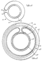
- a spacer 22 (Figure 2) comprising an annular base 24 the outer peripheral edge of which is provided with an upstanding wall 26.
- the wall 26 extends almost all of the way around the periphery of the base 24 and a similar upstanding wall 28 extends around the base 24 at a position spaced slightly from the inner circumference of the base 24.
- the opening in the wall 28 is aligned with the opening of the wall 26 and as shown in Figure 2, each end of the wall 26 is interconnected with a respective end of the wall 28 by a curved end wall 30, the end walls 30 being spaced apart from one another.
- the inner circumferential edge of the base 24 includes an integral enlarged bead 24 a engaged in a recess defined by the hub 12 b of the rotor and an inner part of the flange 14 a of the stator 14.
- the axial dimension of the recess is slightly larger than the axial dimension of the bead 24 a and the circumference of the part of the hub 12 b defining the base of the recess is slightly smaller than the inner diameter of the base 24.
- the rotor 12 and stator 14 are each provided with electrical connectors in the form of sockets for connection to suitable electrical plugs.
- the socket of the rotor 12 is illustrated in Figure 1 and comprises an upwardly extending integral part 12 c defining a recess within which a suitable electrical plug is receivable, a terminal blade or pin 12 d extending within the recess for electrical connection to a respective terminal of the plug connector.
- a ribbon connector 32 in the form of a flat cable comprising a plastics material base having at least one conductive strip laminated therein, is received within the housing 10, one of the conductors being connected to the pin 12 d , and the other end of the conductor being connected to a similar pin provided in the socket connector associated with the stator 14.
- the other conductor of the flat cable are similarly connected to respective terminals in connectors of the rotor and the stator.
- the ribbon connector 32 is wound so as to define a first coiled portion 32 a housed between the upstanding wall 28 of the spacer 22 and the hub 12 b of the first housing portion 12.
- the outermost end of the first coiled portion 32 a extends between the end walls 30 of the spacer 22 and the remaining part of the ribbon connector 32 is coiled to define a second coiled portion 32 b extending between the upstanding wall 26 of the spacer 22 and the upstanding wall 14 b of the second housing part 14.
- the first and second coiled portions 32 a , 32 b are wound in opposite directions as illustrated in Figure 3.
- the base member 24 is of slightly dished form thus, in conjunction with the bearing arrangement, spacing the majority of the base member 24 from the flange 14 a of the stator 14 thereby effecting a reduction in the level of scraping which occurs between the spacer 22 and the rotor 12 and stator 14, and thus in a reduction in the level of noise generated.
Landscapes
- Engineering & Computer Science (AREA)
- Mechanical Engineering (AREA)
- Steering Controls (AREA)
Applications Claiming Priority (2)
| Application Number | Priority Date | Filing Date | Title |
|---|---|---|---|
| GBGB9512741.1A GB9512741D0 (en) | 1995-06-22 | 1995-06-22 | Connector |
| GB9512741 | 1995-06-22 |
Publications (2)
| Publication Number | Publication Date |
|---|---|
| EP0750373A2 true EP0750373A2 (de) | 1996-12-27 |
| EP0750373A3 EP0750373A3 (de) | 1997-12-03 |
Family
ID=10776517
Family Applications (1)
| Application Number | Title | Priority Date | Filing Date |
|---|---|---|---|
| EP96304613A Withdrawn EP0750373A3 (de) | 1995-06-22 | 1996-06-21 | Verbinder |
Country Status (3)
| Country | Link |
|---|---|
| US (1) | US5762506A (de) |
| EP (1) | EP0750373A3 (de) |
| GB (1) | GB9512741D0 (de) |
Families Citing this family (7)
| Publication number | Priority date | Publication date | Assignee | Title |
|---|---|---|---|---|
| DE19926278C1 (de) * | 1999-06-09 | 2001-02-15 | Kostal Leopold Gmbh & Co Kg | Vorrichtung zum Übertragen von Energie |
| US6253131B1 (en) | 1999-09-08 | 2001-06-26 | Paccar Inc | Steering wheel electronic interface |
| JP2002075574A (ja) * | 2000-08-28 | 2002-03-15 | Yazaki Corp | 回転コネクタ |
| US20030167524A1 (en) * | 2000-12-19 | 2003-09-04 | Rooijen Gijs Van | Methods for the production of multimeric protein complexes, and related compositions |
| US6538220B2 (en) | 2001-04-23 | 2003-03-25 | Trw Inc. | Switch pod assembly |
| JP5117528B2 (ja) * | 2010-03-30 | 2013-01-16 | 古河電気工業株式会社 | 回転コネクタ装置 |
| CN104518388B (zh) * | 2015-01-06 | 2017-08-29 | 江苏飞锦达科技有限公司 | 一种用于旋转部件和静态部件之间的连接转换装置 |
Family Cites Families (4)
| Publication number | Priority date | Publication date | Assignee | Title |
|---|---|---|---|---|
| US5171153A (en) * | 1990-10-24 | 1992-12-15 | Kabushiki Kaisha Tokai Rika Denki Seisakusho | Flat cable connector |
| US5409389A (en) * | 1991-12-24 | 1995-04-25 | Furukawa Electric Co., Ltd. | Transmission apparatus between rotatable body and fixed body |
| JP2826009B2 (ja) * | 1992-01-27 | 1998-11-18 | アルプス電気株式会社 | ケーブルリール |
| DE19511654A1 (de) * | 1995-03-30 | 1996-10-02 | Alcatel Kabel Ag | Vorrichtung zur Signalübertragung zwischen zwei Endstellen |
-
1995
- 1995-06-22 GB GBGB9512741.1A patent/GB9512741D0/en active Pending
-
1996
- 1996-06-21 EP EP96304613A patent/EP0750373A3/de not_active Withdrawn
- 1996-06-24 US US08/669,694 patent/US5762506A/en not_active Expired - Lifetime
Also Published As
| Publication number | Publication date |
|---|---|
| EP0750373A3 (de) | 1997-12-03 |
| GB9512741D0 (en) | 1995-08-23 |
| US5762506A (en) | 1998-06-09 |
Similar Documents
| Publication | Publication Date | Title |
|---|---|---|
| EP0243047B1 (de) | Verbindungseinrichtung für eine Übertragungsleitung, die zwei sich relativ zueinander bewegende Teile verbindet | |
| EP2555345B1 (de) | Drehbare konnektorvorrichtung | |
| EP0444584B1 (de) | Elektrische Kabelanordnung | |
| US6299454B1 (en) | Steering column interconnector having conductive elastic rolling contacts | |
| JP4929148B2 (ja) | クロックスプリング装置 | |
| JPH0156511B2 (de) | ||
| US4157854A (en) | Steering column electrical connector arrangement | |
| EP0695000A2 (de) | Drehbarer Verbinder mit Trägerelement | |
| JPH0143988B2 (de) | ||
| EP0863822B1 (de) | Lenkradanordnung | |
| US5762506A (en) | Connector | |
| JP2003502987A (ja) | エネルギー伝達装置 | |
| US5928018A (en) | Rotary contactor for automobile steering wheel | |
| US4657326A (en) | Current conduction connector for the electrical connection of gas bag collision protection installation | |
| EP0715376B1 (de) | Elektrischer Verbinder | |
| US5980285A (en) | Rotary connector apparatus | |
| US4886460A (en) | Electrical connector assembly for a steering wheel occupant cushion restraint system | |
| JP2003523160A (ja) | 電気的な駆動装置、特に自動車のための駆動装置 | |
| EP0741058A2 (de) | Elektrisches Verbindungsgerät zwischen einem Rotor und einem feststehenden Teil | |
| US4975064A (en) | Clock spring interconnector for steering | |
| KR20020013433A (ko) | 회전커넥터 | |
| US5649832A (en) | Device for transmitting signals between two terminals | |
| JPH07307189A (ja) | 接触コイルの収容ハウジング | |
| US5551886A (en) | Current transfer element for steering wheels of motor vehicles | |
| US6770991B2 (en) | Roll connector structure for a vehicle |
Legal Events
| Date | Code | Title | Description |
|---|---|---|---|
| PUAI | Public reference made under article 153(3) epc to a published international application that has entered the european phase |
Free format text: ORIGINAL CODE: 0009012 |
|
| AK | Designated contracting states |
Kind code of ref document: A2 Designated state(s): DE ES FR GB IT |
|
| PUAL | Search report despatched |
Free format text: ORIGINAL CODE: 0009013 |
|
| AK | Designated contracting states |
Kind code of ref document: A3 Designated state(s): DE ES FR GB IT |
|
| 17P | Request for examination filed |
Effective date: 19980223 |
|
| RAP1 | Party data changed (applicant data changed or rights of an application transferred) |
Owner name: LUCAS INDUSTRIES LIMITED |
|
| STAA | Information on the status of an ep patent application or granted ep patent |
Free format text: STATUS: THE APPLICATION IS DEEMED TO BE WITHDRAWN |
|
| 18D | Application deemed to be withdrawn |
Effective date: 20000103 |